© 2019, IRJET | Impact Factor value: 7.211 | ISO 9001:2008 Certified Journal
| Page 1470
COMPARATIVE ANALYSIS ON SEISMIC BEHAVIOR OF R.C.C, COMPOSITE
ENCASED AND COMPOSITE INFILLED FRAMED STRUCTURE
VISHWAS J
1, CHANDRASHEKAR AR
2, CHETAN GONNI S
31
Post Graduate (Structural Engineering), Department of Civil Engineering B.I.E.T, Davanagere, Karnataka INDIA
2,3Asst professor, M Tech, Department of Civil Engineering B.I.E.T, Davanagere, Karnataka INDIA
---***---Abstract - Steel-concrete composite construction arebecoming more popular in recent times and it became world-wide acceptable alternative to pure steel or pure concrete with rebars construction. Compared to other countries, use of steel-concrete composite in India is very less. To achieve present requirement of building composite construction is necessary. In this report, comparison is done for 3 types of materials, R.C.C composite encased and composite infilled material, for 4 different shear wall positions, total 12-models are modelled for 12-storey building assuming building is in seismic zone III. Modelling and analysis is done using software e-tabs, all frames are subjected to gravity loads. Analysis is done using two methods, equivalent static analysis method and response spectrum method for parameters self-weight, lateral forced, story drift, time period, frequency, max story displacement, base shear. It is found that performance of composite framed structure is good in majority of cases for shear wall model 1.
Key Words: CE-composite enclosed, CI- composite infilled, ETABS analysis software, shear connectors, equivalent static analysis, response spectrum analysis
1. INTRODUCTION
Concrete and steel are best and versatile building material available. Concrete have properties like high strength, economical, fire resistance. Steel have properties like light weight structure, high strength than concrete, speed of construction is fast. Here we are not looking for individual advantages, but to enhance the property of both materials. Now a days R.C.C framed structure are more popular for low rise to high rise buildings. To increase efficiency, composite frame can be used instead of R.C.C frame. Though composite frame structures are popular in other countries, it is not used much in India. Steel as a structural member in composite frame, it possess very good performance reducing area of frame.
Shear wall is one of the most important structural component provided in building to improve seismic property of the building.
1.1 COMPONENTS OF COMPOSITE STRUCTURE
Composite column, Composite beam, Composite slab, Shear connection
1.1.1 COMPOSITE COLUMN
Concrete encased in steel section: Rolled steel I-section is encased by concrete to form single unit.
Concrete section, Partially concrete encased-section, Partially concrete encased-section with crossed I section
Concrete infilled tube steel section: Rectangular hallow rolled steel section is filled with concrete to form concrete core.
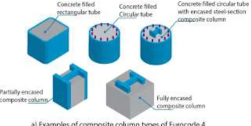
[image:1.595.312.564.450.576.2]Concrete filled rectangular hallow-section with reinforcement, Concrete filled circular hallow-section with reinforcement Concrete filled circular hallow-section with additional I-section
Fig -1: Different Types of Composite Column
1.1.2 COMPOSITE BEAM
© 2019, IRJET | Impact Factor value: 7.211 | ISO 9001:2008 Certified Journal
| Page 1471
Fig -2: Composite Beam1.1.3 COMPOSITE SLAB
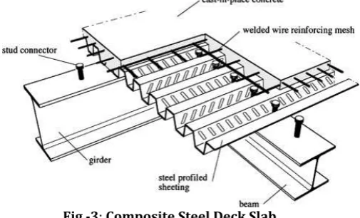
Composite slab is reinforced concrete cast on top of profiled deck-sheet, here profiled sheet acts as formwork. At recent times many construction activities in European and American countries are done using composite slabs due to their high advantages. Shear between slab and beam should be carried by composite action from beam to slab in presence of shear connections. Its proved that structural behavior of both R.C.C slab and composite deck slab remains same.
Fig -3: Composite Steel Deck Slab
1.1.4 SHEAR CONNECTORS
Large amount of shear (approximately 8 times the load on beam) is created between composite slab and steel beam (I-section). This shear is taken by shear connectors which is placed at the interference of composite slab and beam.
Two main function of shear connectors are to transfer shear, to prevent separation of composite slab from beam. In India code used for shear connector are IS 11384-1985
Fig -4: Composite Steel Slab with Shear Connection 1.2 SOFTWARE
In modern periods, having computers in every field of work manual calculations, analysis, design is difficult and time consuming. Now a days structural analysis software play an important role for carrying seismic calculations for infrastructure. E-tabs is an Extended 3-dimentional analysis of building, software developed by CSI-America, generally used for analysis and design of building structures based on various codes. E-tabs is one of the best and most used software for analysis and design of structure used by most of structural engineers in India.
1.3 ADVANTAGES OF COMPOSITE COLUMN
1. In CFST columns, steel lies at outer perimeter where, it performs effectively in bending and tension. It also provides better stiffness as moment of inertia lies away from steel.
2. Encased columns have outer concrete cover so it is very good in fire performance.
3. As composite column acts as formwork, speed of construction is very high. It is one of the biggest advantage for constructers
4. Cross-section dimension of column can be reduced using composite column compared to R.C.C thus reducing weight of building intern reduction of steel in foundation.
5. By varying cross-section of I-section, strength of building can be increased as requirement keeping cross-section of column constant.
1.4 ADVANTAGES OF COMPOSITE BEAM-SLAB
1. We can provide the I-section of less depth than R.C.C beam as per aesthetic requirement without disturbing structural requirement.
2. Using profiled steel sheet deck material depth of slab can be reduced
[image:2.595.305.556.64.227.2] [image:2.595.42.295.398.551.2]© 2019, IRJET | Impact Factor value: 7.211 | ISO 9001:2008 Certified Journal
| Page 1472
6. Composite action have higher stiffness than corresponding steel section
7. By using composite slab (profiled deck sheet) concrete in tension zone can be reduced
8. Composite beam-slab together provides adequate composite action to take gravity loads
2. METHODOLOGY AND MODELLING 2.1 EQUIVALENT STATIC ANALYSIS
In this method, amount of seismic base-shear considered for design of the building is based on approximate period of the building, site class, ground acceleration, building-system type building-system (OMRF/SMRF). This method is good for analyzing simple structure.
2.1 RESPONSE SPECTRUM ANALYSIS
It’s popularly known as dynamic analysis of structure. For analysis it takes values of modal mass participation, time period and modal shapes of the structure for variable frequency. Its calculates response for every natural-mode of vibration.
Table -1: Structural Modelling Parameters
PARAMETER MODEL R.C.C COMPOSITE ENCLOSED MODEL (CE)
COMPOSI TE INFILL
MODEL (CI)
Total storey 12 12 12 Total building
height 36 m 36 m 36 m X-direction bays
width 6 m 6 m 6 m
Y-direction bays
width 5 m 5 m 5 m
Seismic zone III III III Framing type OMRF OMRF OMRF
Soil type Medium Medium Medium Importance
factor (I) 1 1 1
Response
reduction factor 3 3 3 Foundation
support
condition Fixed Fixed Fixed Terrain category 3 3 3
Slab thickness 150 mm 95 mm 95 mm Concrete
grade-column M40 M40 M40
Concrete
grade-slab M30 M30 M30
Rebar yield
strength (fy) N/mm² 500 500 N/mm² N/mm² 500
Steel I-section yield strength
(fy) NA
Fe 350 N/mm² for
column Fe 250 N/mm² for
beams
Fe 350 N/mm²
for column
Fe 250 N/mm² for beams
Beam size in mm 300 × 450 (ISWB 350) 200 × 350 200 × 350 (ISWB 350)
Column size in
mm 300 × 800 (ISWB 500) 300 × 7000
300 × 650 (12mm
thick hallow rectangula
r block) Slab type R.C.C slab Deck slab Deck slab Wall load kN/mm 12.04 12.04 kN/mm kN/mm 12.04 Super dead load
(floor finish and others)
1.5 kN/mm
² 1.5 kN/mm²
1.5 kN/mm²
Live load kN/mm2
² 2 kN/mm² 2 kN/mm²
Table -2: Deck Slab Specifications
PARAMETER VALUES
Deck slab type Filled
Slab depth 95 mm
Deck shear thickness 1 mm Shear stud diameter 19 mm
Shear stud height 150 mm Shear stud tensile strength 400 Mpa
2.3 MODELS
© 2019, IRJET | Impact Factor value: 7.211 | ISO 9001:2008 Certified Journal
| Page 1473
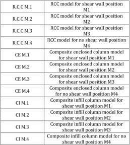
Table -3: Model NamingR.C.C M.1 RCC model for shear wall position M1 R.C.C M.2 RCC model for shear wall position M2 R.C.C M.3 RCC model for shear wall position M3 R.C.C M.4 RCC model for no shear wall position M4
[image:4.595.33.561.52.756.2]CE M.1 Composite enclosed column model for shear wall position M1 CE M.2 Composite enclosed column model for shear wall position M2 CE M.3 Composite enclosed column model for shear wall position M3 CE M.4 Composite enclosed column model for no shear wall position M4 CI M.1 Composite infill column model for shear wall position M1 CI M.2 Composite infill column model for shear wall position M2 CI M.3 Composite infill column model for shear wall position M3 CI M.4 Composite infill column model for no shear wall position M4
Fig -5: R.C.C Model for M1 Shear Wall Position
[image:4.595.299.556.59.372.2]Fig -6: R.C.C Model for M2 Shear Wall Position
Fig -7: R.C.C Model for M3 Shear Wall Position
Fig -8: R.C.C Model for M4 No Shear Wall Position 3. RESULTS
3.1 MAX STOREY DISPLACEMENT
Displacement refers to movement of structural element/node from one position to another, under a load. It may refer to distance or angle. In my model, result shows that there are not much difference between RCC model displacement to Composite model displacement, but for model M4 (no shear wall), results shows that composite model have better deflection control over RCC model.
Table -4: Max Story displacement in X and Y direction ESA
R.C.C CE CI
DIREC
TION X Y X Y X Y
M.1 32.6 32.6 32.1 29.9 29.9 27.4
M.2 19.6 87.4 18.2 71.8 18.1 81.3
M.3 50.0 96.8 49.1 90.3 51.0 97.3
[image:4.595.35.294.110.399.2] [image:4.595.29.569.490.742.2]© 2019, IRJET | Impact Factor value: 7.211 | ISO 9001:2008 Certified Journal
| Page 1474
0 50 100 150 200 250
M.1 M.2 M.3 M.4
Dis
pl
ac
eme
nt
in
mm
Diffrent Shear Wall Postion Models
RCC
CE
CI Chart -1: Max story Displacement in X-Direction for
ESA
Chart -2: Max story Displacement in Y-Direction for ESA
Table -5: Max Story displacement in X and Y direction ESA
RSA R.C.C CE CI
DIRECTI
ON X Y X Y X Y
M1 24.4 22.9 24.1 22.39 22.7 20.9
M2 15.9 55.9 15 48.4 14.7 52.7
M3 34.9 59.6 35.2 58.5 36.1 61.1
M4 132.8 168.2 74.2 97.8 120.2 135.1
Chart -3: Max story Displacement in X-Direction for RSA
Chart -4: Max story Displacement in Y-Direction for RSA
3.2 BASE SHEAR
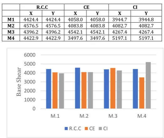
[image:5.595.303.565.417.637.2]Base shear is the maximum expected lateral-force at the base level, due to earth-quake. In the present models, base shear is greater for R.C.C models compared to composite models. having highest at CI-M.4 model and lowest at CE-M.4 and this shows composite enclosed models have good results having reduced base shear compared to R.C.C one and composite infill models have showed good results except M.4 model(with-out shear wall).
Table -6: Base Shear Values
R.C.C CE CI
X Y X Y X Y
M1 4424.4 4424.4 4058.0 4058.0 3944.7 3944.8
M2 4576.5 4576.5 4083.8 4083.8 4082.7 4082.7
M3 4396.2 4396.2 4542.1 4542.1 4267.4 4267.4
M4 4422.9 4422.9 3497.6 3497.6 5197.1 5197.1
Chart -5: Base-Shear Values for Different Models
3.3 LATERAL LOADS FOR EARTH-QUAKE LOAD
Lateral loads are live-loads whose component is horizontal-force, which is acting on a structure; it may be wind load or earth-quake load. Earth-quake load is a lateral live load, it is uncertain, very complex, more compared to wind load. Earth-quake created ground-motion in the form of shake, roll, rattler.
0 50 100 150 200
M.1 M.2 M.3 M.4
Dis
pl
ac
eme
nt
in
mm
Diffrent Shear Wall Postion Models
RCC
CE
CI
0 1000 2000 3000 4000 5000 6000
M.1 M.2 M.3 M.4
B
as
e
She
ar
R.C.C CE CI
750 800 850 900 950
M.1 M.2 M.3 M.4
La
te
ra
l l
oad
© 2019, IRJET | Impact Factor value: 7.211 | ISO 9001:2008 Certified Journal
| Page 1475
Table -7: Lateral Loads on Models based on ESAChart -6: Lateral Loads on Models
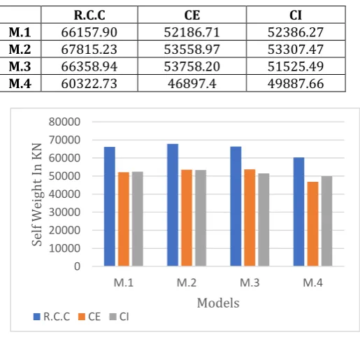
3.4 SELF-WEIGHT
Self-weight is the weight of building. It is always constant. Self-weight changes from structure to structure depends on concrete and rebars/steel provided. In my present model in E-tabs it is evident that composite structure provided less self-weight compared to R.C.C structure in all models.
Table -8: Self-weight of structural models
R.C.C CE CI
M.1 66157.90 52186.71 52386.27
M.2 67815.23 53558.97 53307.47
M.3 66358.94 53758.20 51525.49
M.4 60322.73 46897.4 49887.66
Chart -7: Self-Weight of Models
4. CONCLUSIONS
1. It is found that composite encased and composite infill model performance is better than RCC model in both equivalent static analysis and response spectrum analysis. And response spectrum analysis results found to less compared to equivalent static method of analysis.
2. Comparative results for story displacement shown not much variation for model M1, M2, M3. but for M4 model large variation is found and composite encased model shows good response than the other model. For RCC model, story displacement should be with in h/500 = 72mm but all model without shear wall have exceeds 72 mm displacement. So for safe design, shear wall is necessary.
3. Lateral loads of composite models show lesser value compared to RCC model.
4. Self-weight of composite model is lesser compared to RCC model, for model reduction of self weight compared to RCC is, for CE-M1 26.77% CI-M1 26.28%, M2 26.61%, CI-M2 27.21%, CE-M3 23.43%, CI-CE-M3 28.78% CE-M4 28.62%, CI-M4 20.91% thus load on foundation is reduced intern foundation size is also reduced.
5. Design check shows all model passes except RCC-M4, which fails at bottom columns due to required percentage of steel exceeds 6%. So it can be concluded again composite models possess safe design even without shear wall .
6. Based on results, I can say that composite frame structure is better than RCC framed structure. Beam, column, slab section size can be reduced by using composite material.
REFERENCES
[1] Satish Kumar and D.K. Paul 2 (1994) “3-D analysis of irregular buildings with rigid floor diaphragms, Bulletin of the Indian Society of Earthquake Technology”, Paper No. 343, vol. 31, No. 3, Sept., pp. 141-154.
[2] D. R. Panchal and P M Marathe (2011) “Comparative study of R.C.C., Steel and Composite (G+30 story) building” Institute Of Technology, Nirma University, Ahmedabad [3] Anish N. Shah, Dr. P.S. Pajgade (2013) International Journal of Engineering Research and Applications (IJERA) ISSN: 2248-9622 Vol. 3, Issue 2, March -April
[4] Abhay Guleria (2014) Undergraduate “Structural Analysis of a Multi-Storeyed Building using ETABS for different Plan Configurations”, Dept. of Civil Engineering, J.N.G.E.C. Sundernagar, Sundernagar,
[5] A Shweta Wagh, Dr. U. P. Wagh (2014) “Comparative study of R.C.C and Steel Concrete Composite Structures” Int. Journal of Engineering Research and Applications www.ijera.com ISSN : 2248-9622, Vol. 4, Issue 4
R.C.C CE CI
M.1 878.42 871.062 808.32
M.2 901.19 837.6 837.7
M.3 874.23 855.69 860
M.4 880.31 830 860
0 10000 20000 30000 40000 50000 60000 70000 80000
M.1 M.2 M.3 M.4
Se
lf
W
eight
In
KN
Models
R.C.C CE CI
750 800 850 900 950
M.1 M.2 M.3 M.4
La
te
ra
l l
oa
d
[image:6.595.38.296.491.732.2]© 2019, IRJET | Impact Factor value: 7.211 | ISO 9001:2008 Certified Journal
| Page 1476
[6] Mohd Amir Khan (2015) “Comparative Study of R.C.C & Structural Steel-Concrete Composite Frame for Linear and Non-Liner Analysis” April
[7] “Comparative Study on Multi-storey Structure of R.C.C and Composite Material” (2015) ISSN (Print) : 0974-6846 [8] IS 456 (2000), “Plain and Reinforced Concrete–Code of Practice”, Bureau of Indian Standards, New Delhi, India. [9] “Comparative Study on Multi-storey Structure of R.C.C and Composite Material” (2015) ISSN (Print) : 0974-6846 April
BIOGRAPHIES
oto
or
VISHWAS J
M. Tech (structural engineering) Department of civil engineering B.I.E.T college Davanagere
CHANDRASHEKAR A R Asst. professor
Department of civil engineering B.I.E.T college Davanagere
CHETAN GONNI S Asst. professor