© 2019, IRJET | Impact Factor value: 7.34 | ISO 9001:2008 Certified Journal | Page 1372
Simulation of 2.4GHz Microstrip patch Antenna using EBG Structure
Bharamappa Kattimani
1, Dr. Jagadeesha S
21
Department of E&C, VSM’
SSRKIT Nipani
2Department of E&C, SDMIT Ujire
---***---Abstract -
A microstrip patch antenna is low profileantenna mounted over a high impedance electromagnetic bandgap (EBG) substrate is proposed. In this paper, Microstrip patch antenna with rectangular EBG structure is proposed and studied. The proposed antenna has compact structure
with a total size of 29.44x38.036mm2. The designed antenna
resonates at multiple frequencies with improved return loss,
bandwidth and gain.The resonant frequency of the antenna
2.35GHz and 2.33GHz without and with EBG and improved return loss of -17.61dB and -18.30dB. With rectangular EBG the antenna gives improved gain of 2.14 dB. The Proposed antenna is simulated by using the method of moment based commercial software (IE3D) and simulated results are in good with practical antenna characteristics.
Key Words
:
EBG, Microstrip patch antenna, Return
loss, Gain, bandwidth
1. INTRODUCTION
Antenna is one of the important elements in the RF system for receiving or transmitting the radio wave signals from and into the air as the medium. The microstrip antenna has been said to be the most innovative area in the antenna engineering with its low material cost and easy fabrication. Microstrip patch antennas have various application in satellite communications, wireless systems such as ATM Wireless Access (AWA) and millimeter-wave automobile sensors, aerospace, radars, biomedical applications, reflector feeds, because of their advantages of a low profile, light weight. With Advance of wireless communication systems and increasing importance of other wireless applications, wide band and low profile antennas are in great demand for both commercial and military applications [1-2].There many disadvantages in Microstrip antenna to overcome those by using a metamaterial to apply with the microstrip antenna [2]. The metamaterial refers to an engineered material whose behaviors or properties are naturally non-existent Another metamaterial suitable for the electromagnetic applications is the electromagnetic band gap (EBG) structure [3]. By loading the EBGs periodically on the substrate, a band gap can be created for frequencies around the operating
frequency of the antenna. Such structure can stop the propagation of surface waves, which can be excited along the high dielectric substrate material [4]. Several types of EBG structures have been proposed for performance improvement of the microstrip patch antennas [5].The
inclusion of EBG in microstrip antenna design allows gain enhancement, enhanced directivity, relative bandwidth improvement and size miniaturization [6]. EBG structures possess unique electromagnetic properties that have led to a wide range of applications [7].
Fig1 (a) Geometry of patch antenna
Fig 1(b) Geometry of Patch with EBG
[image:1.595.357.507.259.568.2] [image:1.595.331.535.598.715.2]© 2019, IRJET | Impact Factor value: 7.34 | ISO 9001:2008 Certified Journal | Page 1373
Fig 2(a) Simulated result of Base antenna
Fig 2(b) Simulated result of patch with EBG
Fig 2(c) VSWR of Base antenna with EBG
Fig 3(a) VSWR of Base antenna
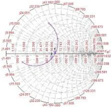
Fig 3(b) Smith Chart of Base antenna
Fig 3(c) Smith Chart of Base antenna with EBG
The patch is surrounded by rectangular shape EBG structure as indicated in the below figures 4(c) & 4(d). The total area occupied by the base shape patch is 29.44x38.036mm2. The
[image:2.595.44.540.21.720.2] [image:2.595.344.529.316.496.2]© 2019, IRJET | Impact Factor value: 7.34 | ISO 9001:2008 Certified Journal | Page 1374
Fig 4(a) & 4 (b): Fabricated antennas with top view and bottom view of Basic microstrip antenna
Fig 4(c) & 4 (d): Fabricated antennas with top view And bottom view of Patch with EBG
6GHz spectrum analyzer, a 12.4 GHz tracking generator,
and a 6GHz directional coupler. By connecting these devices together (with the included cables) the system functions as a scalar network analyzer, providing the tools you need to perform VSWR and return loss measurements at frequencies up to 6 GHz . For all cases, the simulated results are obtained and are compared to the experimental results.Fig 5(a) Practical Simulated result of Base antenna
Fig 5(b) Practical VSWR result of Base antenna
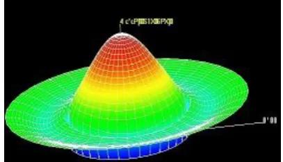
Fig 5(c) Practical Radiation pattern of Base antenna
[image:3.595.67.556.40.530.2] [image:3.595.300.548.47.499.2] [image:3.595.51.273.269.410.2] [image:3.595.322.544.528.730.2] [image:3.595.48.273.550.731.2]© 2019, IRJET | Impact Factor value: 7.34 | ISO 9001:2008 Certified Journal | Page 1375
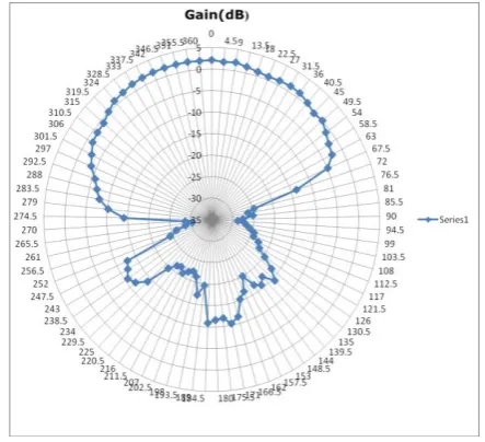
Fig 6(b ) Gain plot in polar of Base antenna without EBGFig 6(c) Gain plot in polar of patch With EBG
The Simulated and measured return loss characteristics of antenna are shown in fig 2(a) & 5(a). And also VSWR characteristics of antenna shown in fig 3(a) & 2(c). Agreement between measured and simulated results is good. The results are shown in table 1. The results indicate that the proposed antenna performance with periodic EBG structures is improved i.e., the Return loss and gain are enhanced.
Prototype antenna Resonance frequency Fr(GHz) Return loss(db) Gain(db)
Sim Prc Sim Prc Sim Prc Base
antenna without EBG
f1=2.4 f1=2.35 -17.28 -17.61 2.35 1.99
[image:4.595.62.261.76.268.2]With EBG f1=2.4 f1=2.34 -17.9 -18.3 2.27 2.09
Table 1: Results of proposed antenna with EBG structure
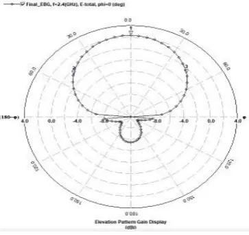
The directivity of proposed antennas are also studied, It has been observed that with EBG there is an improvement in directivity of all antennas. The base antenna gives directivity of 5.23 dBi without EBG and 6.32 with EBG. Also the radiation patterns have been studied for all the antennas with EBG structure and it is shown in fig 5(c) to 6(a). It is observed that the radiation patterns are broadside. The characteristics of proposed antennas were simulated by using software IE3D and verified experimentally by using Scalar network analyzer. For all cases, the simulated results are obtained and are compared to the experimental results. They are shown in figure 5(a) &5(b). From the results it is clear that simulated results are in good agreement with measured results.
1.2. Conclusion
The performance improvement of a microstrip patch antenna with the EBG structure has been investigated. The EBG structure demonstrated the effects of surface wave suppression and reduction on broadside radiation power. The Gain obtained is 2.14 dBi and broadside radiation patterns are achieved. Measured values of resonant frequencies and return loss -18.30dB and VSWR 1.90 for these antennas have been found to agree well with the simulated ones. The EBG structure may find various applications for antenna and array in communications.
1.3. REFERENCES
[1] Jagadeesha.S, Vani.R.M and P.V.Hunagund “A Self-similar Fractal Antenna with square EBG Structure,” International Joural of Engineering Research & Technology (IJERT) Vol.2 Issue 2, February-2013 ISSN:2278-0181
[2] Ruchika Gupta, Mithilesh kumar, “Bandwidth Enhancement of Microstrip patch Antenna by Implementing Electromagnetic Band gap (EBG) Structure,” 2012 4th
International Conference On computational intelligence and communica Network 978-0-695-4850-0/12$26.00©2012 IEEE DOI10.1109/CICN.2012.58
[3] Praphat Arnmanee, “Gain Improvement of Microstrip patch Antenna using Octagonal-Loop Meta surface Superstrate and octagonal-Shaped EBG structure for 2.4
GHz Band Application,” 2018 15th International
Conference on Electrical Engineering/Electronics, Computer, Communication and Information Technology 978-1-5386- 3555-1/18/$31.00©2018 IEEE
[4] Harish Kumar, Manish kumar, Rajeev Kanth, “Study on Band Gap Behaviour of Electromagnetic Band-Gap (EBG) Structure with Microstrip antenna,” ISBN 978-89-5519 -163-9Feb 19~22, 2012 ICACT 2012
[image:4.595.69.251.305.476.2]© 2019, IRJET | Impact Factor value: 7.34 | ISO 9001:2008 Certified Journal | Page 1376
with Band Gap Structure,” ICMMT 2008 Proceedings978-1-4244-1880-0/08/$25.00© 2008 IEEE
[6] Gnanam Gnanagurunathan and Krishnasamy T.Selvan, “Improved radiation characteristics of A patch antenna with square slot EBG,” 2011 IEEE International RF and Microwave Conference (RFM 2011 ), 12th - 14th December 2011, Seremban, Malaysia 978-1-
4577-1631-7/$26.00 ©2011 IEEE.
[7] B. Ramesh, Dr. V. Rajya Lakshmi, “Design Of A Rectangular Microstrip Antenna Using EBG Structure,” International Journal of Engineering Research & Technology (IJERT) Vol. 2 Issue 7, July – 2013IJERTIJERT ISSN: 2278-0181.