A RESEARCH PAPER ON DESIGN AND EXPERIMENTATION ON
CONTINUOUS LOOP DEMULSIFIER
Divij Gupta
1, Ketan Singhvi
21,2
B.E. Mechanical
---***---Abstract -This paper explains the working of an Electrocoalescer used to separate water from crude oil. This separation is of utmost importance and economic relevance affecting the quality of crude oil. The water present in crude oil enhances corrosion in refineries, reduces quality of crude oil and its by-products, and catalysis occurs. Hence we have developed a practical and low cost model of an electrocoalescer that increases the demulsification rate and improves the oil quality.
Key Words: electrocoalescer, crude oil, demulsification, catalysis
1. INTRODUCTION
India imports more than 82% of its oil needs. Oil water separators or demulsifiers are hence of great importance today. Water molecules induced during extraction of crude oil from 4000 m below sea level, form an emulsion with the oil that corrodes the process equipment, drastically reduces oil quality and may render it poisonous. Therefore it is necessary to keep the water below 0.3% by volume and salt below 10 lbs PTB (per thousand barrels). Other separation processes like gravity separation, chemical demulsification, centrifugal separation etc. used currently either have high maintenance and running costs or low production rates.
Hence we are developing an electrostatic separator that is continuous. It will maintain the industry standards of crude oil. Also electrocoalescer will potentially reduce the cost of production of petroleum products. High voltage electricity is used to induce opposite dipole charges in small water droplets and coalesce the water droplets so that they fall under the action of gravity
2. LITERATURE REVIEW
In [1], the researchers showed that the dependency of water drop in emulsion (water and oil) in conductivity for specific phase of medium. The researchers used two method to do this experiment, one was cone-dimple method and other was cone-spray method. In the experiment of cone-dimple method was performed under the silicon oil and this was done by increasing its conductivity and inserting peperazine and D130. But the reason behind performing this experiment was difficult to explain as per the researchers, but they assumed that this can be due to high conductivity of medium to form the jet, unlike the dielectric medium. Thus, they concluded that this happen because the charge travel between the high conductivity medium and because of this it generates the tangential stress at the interface which results in formation of jet.
From this experiment that have observed that the coalescence of oil in a medium, cone dimple method is dielectric in medium conductivity due to properties of crude oil, and concluded that how electric field depends on coalescence method that affect the construction of parts like desalters and dehydrators and separation of water.
In [2], the authors shows that how the water drops id separated due to electrocoalescence process. This process can get more efficient by different methods like applying gravity, improvement in Stokeslet interaction in hydrodynamics, applying high electrostatics, electric field which is dependable that can be accomplished by high conductivity of drop. Hence, the authors finally concluded that in electrocoalescer process separation of drop can be achieved by verified experimental data.
In [3], the researchers checked the coalescence of uniform and non-uniform electric field in two mixture (water-in-oil mixture and oil-in-oil mixture). By the data the researchers observed that in water-in-oil mixture, the uniform and symmetric non-uniform electric is less advantages than the asymmetric non-non-uniform electric field and in case of oil-in-oil mixture it was completely opposite. Hence, the researchers concluded that for optimum results the electrode should be coated so that they can produce more asymmetric electric field and dependency of efficient electrode is on properties of dispersed and continuous phase.
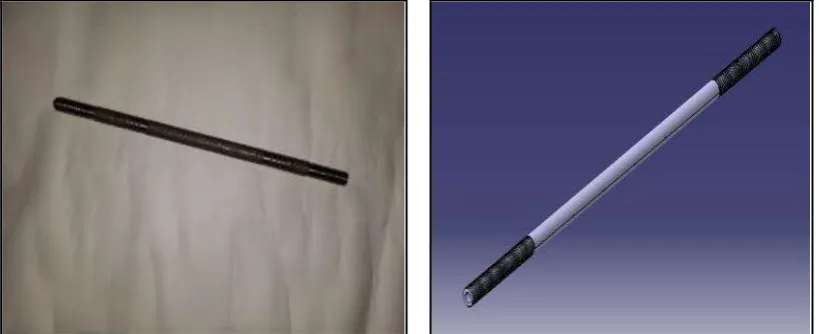
ID - 7 mm
Orifice diameter - 1 mm
Length - 400 mm
[image:2.595.94.504.336.503.2]
Fig -1: Distributor
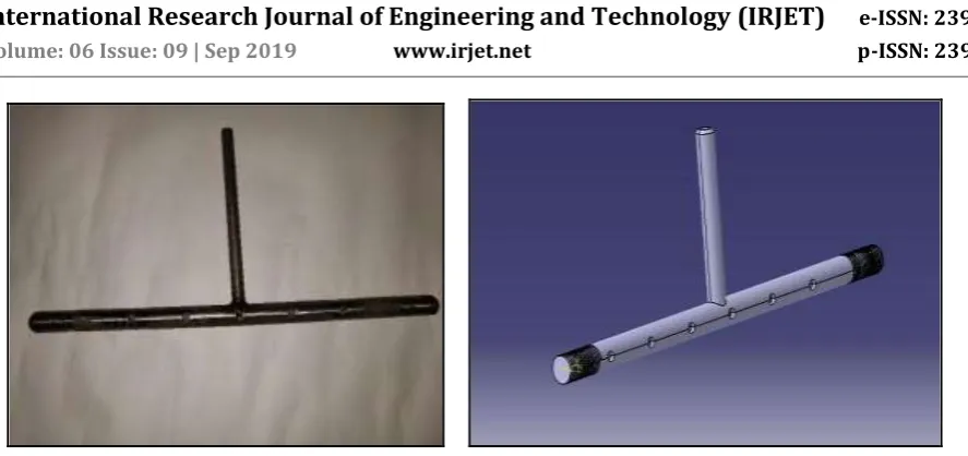
3.2 Collector:
A hollow tube with holes in staggered position with a pipe in the middle is used to collect pure oil after separation. Since oil is less dense it enters the collector from underneath through the holes and exits through the pipe due to pressure exerted on it.
Material used: SS304
Dimensions: OD- 16 mm
ID- 10 mm
Orifice diameter- 6 mm
Pipe diameter: OD- 8 mm
Fig -2: Collector
3.3 Bigrid Electrodes:
Two Grid shaped Electrodes are used to create a uniformly distributed electrostatic field in the entire vessel. This grid or antenna shape allows for a much strong and uniform electrostatic field. The voltage applied depends on the distance between the surfaces of these electrodes, which is to be roughly 1 kV/cm or more.
Material used: SS304
Dimensions: Main Rod Diameter- 10 mm
Length- 340 mm
Grid Rod Diameter- 6 mm
Length- 120 mm
Pitch of Grid Rods- 20 mm
Fig -3: Bigrid Electrodes
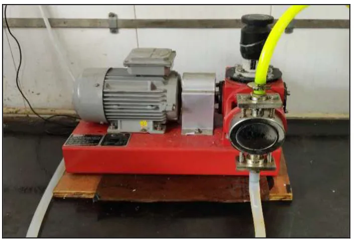
3.4 Pump:
A reciprocating plunger pump (dosing) is used to pump the emulsion in the vessel via the distributor.
Specifications:
[image:3.595.83.513.482.653.2]Fig -4: Pump
3.5 Electrocoalescer Vessel:
An acrylic vessel is used to mount all the components of the demulsifier and inspect the separation of the two liquids. Components are mounted in the following order from top to bottom- Collector, Electrode, Distributor, Electrode. In this vessel the actual coalescence and separation occurs.
Material used: Acrylic
Dimensions: Outer Diameter- 190 mm
Thickness- 5 mm
PCD for fasteners- 250 mm
Fig -5: Electrocoalescer Vessel
3.6 High Voltage Amplifier:
[image:4.595.164.433.535.707.2]Fig -6: High Voltage Amplifier
4. WORKING PRINCIPLE
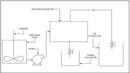
A Demulsifier/Electrocoalescer works on the principle of electrophoresis. Due to the uniform electrostatic field between two electrodes, an electric dipole charge is induced in the micro droplets present in the crude oil resulting in a charge density. The polarity of the dipole charge developed in any droplet depends on the proximity of that droplet to the electrode. The droplets near the positive electrode develop a positive dipole and droplets near the negative electrode develop a negative dipole. The opposite dipole charges and charge density between carrying fluid and micro-droplets act on droplets causing them to move and coalesce to form large drops of water sedimenting quickly under the due to gravity. This water is then drained via the drain valve. The separation percentage of water and its residence time depends upon various factors like intensity of electric field, flow rate of emulsion, electronic configuration etc.
Fig -7: Diagrammatic Representation of Continuous Loop Demulsifier
5. WORKING OF CONTINUOUS LOOP DEMULSIFIER
[image:5.595.69.527.412.668.2]1) Preparation of Emulsion:
An oil-in-water emulsion is prepared by mixing 90% oil and 10% water. This mixture is homogenized using a high speed stirrer for 3 minutes. A white homogenous emulsion is formed.
Emulsion contents: 9000 mL oil
[image:6.595.186.411.371.685.2]1000 mL water
Fig -8: Homogenization of emulsion
2) Assembly and Preparation of Setup:
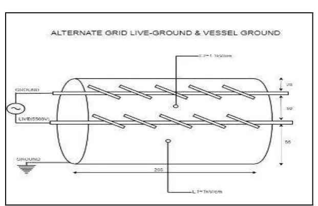
The Electrocoalescer setup is assembled according to the required electric configuration to be used. We have used Alternate Live Ground Vessel Ground configuration for maximum separation and lowest residence time.
Frequency- 50 Hz
Fig -9: Schematic Diagram of Alternate Bigrid Live Ground and Vessel Ground
3) The emulsion is pumped into the coalescer vessel at a rate of 0.3 lph and the stopwatch is started. The experiments is conducted for about 30 minutes.
4) The Grid Electrodes are supplied with 5000 V of electricity using a high voltage amplifier.
5) During the experiment as separation occurs, the oil is collected in an oil tank. Within regular intervals of 3 minutes samples are collected in numbered sampling tubes.
6) The collected samples are then tested for water percent by volume using Karl Fischer’s titration.
7) Karl Fischer’s Titration:
Toluene, Dried Methanol, Chloroform and Karl Fischer’s Solution are poured in required quantities in the apparatus’ flask. The setup and stirrer is started and approximately 30 drops of sample oil is poured in the flask using a syringe.
Fig -10: Karl Fischer’s Titration Apparatus and Solutions
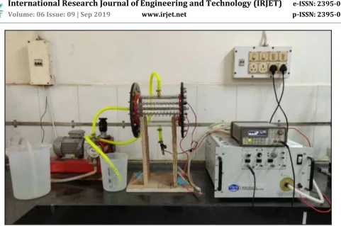
[image:7.595.112.486.508.648.2]Fig -11: Experimental Setup of Continuous flow Electrocoalescer
8. RESULTS
8.1 Observations:
1) The water droplets start to coalesce as soon as the emulsion enters the electric field.
2) The droplets coalesced and form bigger drops.
3) These drops fall under the action of gravity and water gets collected in the lower part of the vessel due to higher density.
4) Pure unadulterated oil is collected through the collector in a separate tank.
5) Total water used-1160 mL
Total water separated-1100 mL
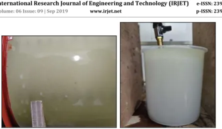
Figure 12: Water drops coalescing and Figure 13: Water after separation
Falling under gravity
[image:9.595.80.525.49.307.2]8.2 Results of Karl Fischer’s Titration:
Table 1: Karl Fischer’s Titration Result
Sample Number Weight (mg) Volume Displaced (mL) % Moisture by weight in collected oil
1 127.07 0.294 1.1744
2 129.60 0.289 1.1358
3 121.69 0.287 1.2013
4 132.46 0.261 1.0039
5 121.54 0.457 1.9128
6 131.19 0.180 0.6964
7 144.10 0.284 1.0003
8 136.78 0.010 0.0371
9 167.61 0.294 0.8903
10 130.95 0.292 1.1318
1) Maximum percentage of moisture- 1.9128%
2) Minimum percentage of moisture- 0.0371%
Chart -1: Sample number v/s percentage separation of water
9. CONCLUSIONS
1) The experimental setup successfully demulsifies the water-in-oil emulsion in a continuous loop. 2) Since there was no sparking in the setup, the electric field of 1 kV/cm is apt for electrocoalescence. 3) Satisfactory percentages of separation were achieved during the experimentation.
10. FUTURE SCOPE
1) Further experiments are to be conducted to find:
a) Variation of percentage of coalescence with change in frequency. b) Dependence of separation and quality of oil on the flow rate of emulsion.
c) Residence time, position of distributor, electric field dependency on percentage water cut in emulsion. 2) Further analysis on optimum size of water droplets for coalescence to occur.
3) Designing of experiments to reduce sparking in coalesce due to water chain formation.
4) Design and development of systems with higher flow rate and lower residence time for faster production rate.
11. REFERENCES
1) “Modes of coalescences of aqueous anchored drops in insulating oil under electric field.” Prof. Vikky Anand, Vinay Juvekar, Rochish Thaokar Date of Publication: 03 February 2019, Volume 568 https://www.sciencedirect.com/science/article/abs/pii/S0927775719300822
2) “Modelling and particle simulation of electrocoalescence of a water in oil emulsion.” Prof. Vikky Anand, Roshan Patil, Vijay M. Naik, Vinay A. Juvekar, Rochish M. Thaokar Date of Publications: 04 December 2018, Volume 121 https://www.sciencedirect.com/science/article/pii/S0098135418312754
3) “Electro-coalescence in non-uniform electric field.” Prof. Sameer Mhatre, Rochish M. Thaokar Date of Publications: 25 July 2015, Volume 96 https://www.sciencedirect.com/science/article/abs/pii/S0255270115300763
4) “Drop-drop coalescence in an electric field: the effect of applied electric field and electrode geometry.” Prof. John S. Eow, Mojtaba Ghadiri Date of Publications: 23 January 2003, Volume 219, https://www.sciencedirect.com/science/article/abs/pii/S0927775703000517