Digital pulse interval modulation for indoor optical wireless
communication systems
HAYES, Andrew Robert
Available from Sheffield Hallam University Research Archive (SHURA) at:
http://shura.shu.ac.uk/7263/
This document is the author deposited version. You are advised to consult the
publisher's version if you wish to cite from it.
Published version
HAYES, Andrew Robert (2002). Digital pulse interval modulation for indoor optical
wireless communication systems. Doctoral, Sheffield Hallam University.
Copyright and re-use policy
LEARNING CENTRE
CITY CAMPIUS,
HOWARD
STREET
SHEFFIELD SI 1WB
1 0 1 6 24 1 84 4
Fines are charged at 50p per hour
- 7 NOV 2003
3
,'S to ^
0 ^
m
iop/y1
1 1 NOV 2003
p
1 2 NOV 2Q03
“
3
OCT2m
ProQuest Number: 10697076
All rights reserved
INFORMATION TO ALL USERS
The quality of this reproduction is dependent upon the quality of the copy submitted.
In the unlikely event that the author did not send a com plete manuscript and there are missing pages, these will be noted. Also, if material had to be removed,
a note will indicate the deletion.
uest
ProQuest 10697076
Published by ProQuest LLC(2017). Copyright of the Dissertation is held by the Author.
All rights reserved.
This work is protected against unauthorized copying under Title 17, United States C ode Microform Edition © ProQuest LLC.
ProQuest LLC.
789 East Eisenhower Parkway P.O. Box 1346
Digital Pulse Interval Modulation
for Indoor Optical Wireless
Communication Systems
Andrew Robert Hayes
A thesis submitted in partial fulfilment of the requirements of
Sheffield Hallam University
for the degree of Doctor of Philosophy
Abstract
Over the past decade, infrared has attracted a considerable amount of interest as an alternative medium to radio for short-range indoor wireless local area networks. Infrared offers a number of significant advantages over its radio frequency counterpart, such as the abundance of bandwidth that is currently unregulated worldwide, the availability of low cost emitters and detectors, inherent security and resistance to multipath fading. The work presented in this thesis focuses on modulation techniques, the fundamental aim being to assess the suitability of digital pulse interval modulation (DPIM) for use in indoor optical wireless communication systems.
Infrared transceivers are subject to eye safety regulations, and consequently power efficiency is an important criterion when evaluating modulation techniques. From the error probability analysis carried out on the non-distorting additive white Gaussian noise channel, it is shown that DPIM is able to trade off power efficiency against bandwidth efficiency by increasing the number of bits per symbol. Furthermore, by encoding an additional bit per symbol, DPIM can outperform pulse position modulation (PPM) both in terms of power efficiency and bandwidth efficiency when simple threshold detection is employed.
Indoor optical wireless systems generally operate in the presence of intense ambient light, emanating from both natural and artificial sources. Along with contributing to the generation of shot noise, artificial ambient light sources also introduce a periodic interference signal which can have a detrimental effect on link performance. Original analysis is presented which examines the error performance of DPIM in the presence of interference from a fluorescent lamp driven by a high-frequency electronic ballast, which is potentially the most degrading source of ambient light. It is found that such interference results in an average optical power requirement that is almost independent of the bit rate. The analysis then goes on to consider the effectiveness of electrical high-pass filtering as a simple means of mitigating the effect of the interference, taking into account the baseline wander introduced by the high-pass filter. DPIM was found to be more susceptible to the effects of baseline wander compared with PPM, a finding which is supported by the original analysis carried out on the power spectral density of the scheme. Consequently, whilst electrical high-pass filtering was found to be very effective at high bit rates, significant power penalties are still incurred at low to medium bit rates.
In non-directed line of sight and diffuse link configurations, multipath propagation gives rise to intersymbol interference (ISI), which must be taken into account for data rates above 10 Mbit/s. Original analysis is presented which examines the unequalized performance of DPIM in the presence of ISI. From this analysis, it is found that on any given channel, the improved bandwidth efficiency of DPIM results in lower average optical power penalties, compared with PPM. One novel technique which can be used to make DPIM more resistant to the effects of ISI is to add a guard band to each symbol, immediately following the pulse. Original contributions are presented which evaluate the effectiveness of this technique. To quantify the results obtained, analysis is also carried out on DPIM using a zero-forcing decision feedback equalizer (ZF-DFE), which represents a more traditional approach to mitigating the effects of ISI. It is shown that the guard band technique offers a similar level of performance to the ZF-DFE on all but the most severe channels, and has the advantage of reduced cost and complexity compared with implementing a ZF-DFE.
Acknowledgements
The work presented in this thesis was carried out in the Electronics Research Group within the School of Engineering at Sheffield Hallam University. The work was funded by a University of Sheffield - Sheffield Hallam University joint studentship award, which is gratefully acknowledged.
I would like to thank my director of studies, Professor Z. Ghassemlooy, for his advice, guidance, support and constant enthusiasm throughout this work. I would also like to thank him for proof reading this thesis, and for giving me the opportunity to undertake my studies in the first place.
Sincere thanks also goes to my second supervisor, Dr. N. L. Seed from the University of Sheffield, for providing invaluable help and advice throughout this work. In addition, a word of thanks must also go to Dr. R. Saatchi and Dr. R. McLaughlin for helping me out from time to time.
I would also like to thank my colleagues in the Electronics Research Group, both past and present, for sharing a few laughs with me and generally making my time in Sheffield a very enjoyable experience. Also, a work of thanks goes to the technical and secretarial staff within the School of Engineering who assisted me during my studies.
Declaration
No portion of the work referred to in this thesis has been submitted in support of an application for another degree or qualification to this, or any other university, other institute of learning, or industrial organisation.
Andrew Robert Hayes
Glossary of Abbreviations
1GS One guard slot 2GS Two guard slots AC Alternating current APD Avalanche photodiode
AWGN Additive white Gaussian noise BER Bit error rate
BPSK Binary phase-shift keying DC Direct current
DFE Decision feedback equaliser DPIM Digital pulse interval modulation
DPIM(IGS) DPIM with a guard band consisting of one slot DPIM(2GS) DPIM with a guard band consisting of two slots DPIM(NGB) DPIM with no guard band
DPPM Differential pulse position modulation DSSS Direct sequence spread spectrum ERP Emitter radiation pattern
FHSS Frequency-hopping spread spectrum FIFO First-in first-out
FOV Field of view
FPGA Field programmable gate array FSF Frequency scaling factor GBP Gain bandwidth product HDL Hardware description language HPF High pass filter
IEC International Electrotechnical Commission IEEE Institute of Electrical and Electronics Engineers IID Independent, identically distributed
IM/DD Intensity modulation with direct detection IrDA Infrared Data Association
ISI Intersymbol interference
ISM Industrial, scientific and medical LAN Local area network
LOS Line of sight
MAP Maximum a posteriori
ML Maximum likelihood
MLSD Maximum likelihood sequence detector MPPM Multiple pulse position modulation MSE Mean square error
NGB No guard band
NPV Nearest preferred value NRZ Non return to zero 0 0 K On-off keying
OOK-NRZ On-off keying using non return to zero signalling OOK-RZ On-off keying using return to zero signalling PC Personal computer
PDA Personal digital assistant PER Packet error rate
PIM Pulse interval modulation PIN Positive-intrinsic-negative PPM Pulse position modulation
PPM(MAP) PPM using a maximum a posteriori detector PPM(TH) PPM using a threshold detector
PSD Power spectral density PWM Pulse width modulation
QAM Quadrature amplitude modulation QPSK Quadrature phase-shift keying RAM Random access memory RC Resistor capacitor RMS Root mean square RZ Return to zero
RZI Return to zero inverted SER Slot error rate
SNR Signal to noise ratio
TH Threshold
Glossary of Symbols
A Pulse amplitudea Constant related to RMS delay spread
A\ Constant which relates low-frequency interference amplitude with IB A2 Constants which relates high-frequency interference amplitude with IB
a, OOK bit sequence
at Value of the penultimate bit in sequence a,
au Value of the 7th bit in sequence a,
Ajj Matched filter output for bit sequence a„ sampled at end of 7th bit period
an DPIM(IGS) slot sequence
b PPM slot sequence containing n symbols b, PPM/DPIM slot sequence
bi Value of the penultimate slot in sequence b,
bjj Value of the 7th slot in sequence b,
BitJ Matched filter output for slot sequence b/, sampled at end of 7th slot period b* DPIM(NGB) slot sequence
h k Estimate of b*
bm_x Value of (m-l)* slot in a DPIM sequence
bm Value of m* slot in a DPIM sequence
bm+1 Value of (m+1)* slot in a DPIM sequence
h Estimate of bm ,
° m- 1 m ~ l
u Estimate of bm um
h Estimate of bm.,
°m\ 1 m+1
C(z) Two-sided z transform of ck c0 Zero tap of ck
Cj Discrete-time equivalent impulse response of cascaded transmitter filter, high-pass filter and receiver filter
Ck Discrete-time equivalent impulse response of cascaded transmitter filter, channel and receiver filter
D Number of bits in a packet
Dmean Mean delay of channel
Drms Channel RMS delay spread
Dt Normalised delay spread
/ Frequency
f c High-pass filter cut-on frequency
fc.off Predetection filter cut-off frequency
fhigh Electronic ballast switching frequency
gif) Impulse response of high-pass filter
Go Optical gain of channel
go Zero tap of gk
gk Discrete-time equivalent impulse response of transm WMF
go u tif) Output of high-pass filter
H{co) Transfer function of predetection filter
H{s) Transfer function of Bessel filter
h{t) Impulse response of channel
Havg Average received irradiance
I Number of possible values for the product anan+k
h DC photocurrent generated by background radiation
Ipk-pk Peak-to-peak interference signal photocurrent
J Length of truncated system impulse response
K Number of distinct sequences
L Order of PPM and DPIM
havg Average DPIM symbol length
M Total number of bits over a 20 ms interval
m Number of bits/slots in sequence
ntjiit) Interference photocurrent from fluorescent lamp
M highif) High-frequency component of nijiit)
mk Fluorescent light interference signal sample
m io w it) Low-frequency component of m jiit)
N Number of slots under consideration
nit) Shot noise
nk Noise sample
No Noise power spectral density (single-sided)
Pierror | one) Probability of error given that a one was sent
Pierror \ zero) Probability of error given that a zero was sent
Pierror) Overall probability of error
P i f ) Fourier transform of pulse shape
Pione) Probability of a one
P(s0 1 zero) Probability of s0 given that a zero was sent
Pit) Impulse response of transmitter filter
Pizero) Probability of a zero
p
1 avg Average optical power
Pe,bit,00K Probability of bit error for OOK
Pe,bit,PPM Probability of bit error for PPM(TH and MAP)
Pe,slot,DPIM Probability of slot error for DPIM
Pe,slot,DPIM(lGS) Probability of slot error for DPIM(IGS)
Pe,slot,DPIM(NGB) Probability of slot error for DPIM(NGB)
Pe,slot,PPM(TH) Probability of slot error for PPM(TH)
Pe,slot,ZF-DFE Probability of slot error for DPIM(NGB) using a ZF-DFE
Pe,symb,PPM(MAP) Probability of symbol error for PPM(MAP)
Pe,symb,PPM(TH) Probability of symbol error for PPM(TH)
Pib,) Probability of occurrence for slot sequence b,
Pi Probability of getting the f1anan+k product
p
1 max Maximum optical transmit power
Prx Average received optical signal power
P TX Average transmitted optical signal power
q Electron charge Q i) Marcum’s ^-function R Photodetector responsivity
rit) Impulse response of receiver filter
Rb Bit rate
RC Filter time constant
Rk Slot autocorrelation function s Laplace variable
Sico) Fourier transform of signal
So Sample value at output of receiver filter
Saif) PSD of DPIM slot sequence
S cif) Continuous component of Sa(f)
S c,PPMif) Continuous component of electrical PSD of PPM
s<tf)
Discrete component of Sa(f)Sd,PPM.if) Discrete component of electrical PSD of PPM
SoPIMij) Electrical PSD of DPIM
SDPmit) DPIM slot sequence
SNRmax Maximum SNR at output of predetection filter
SooK-RZ(y=o.5)(f) Electrical PSD of OOK-RZ with y= 0.5
Sppm(J) Electrical PSD of PPM
t Time
T Pulse duration
t0 Sampling time
Tb Bit duration
Ts Slot duration
Tsymb Symbol duration
u(t) Unit step function W(z) Factor of C(z)
W*(H z) Factor of C(z) {complex conjugate of W(z)} Tap coefficients of l/W * (1/z *)
x(t) Intensity or power of optical source
y(t) Photocurrent
yi Receiver filter output corresponding to penultimate bit/slot in sequence a/b,
yj Receiver filter output corresponding to sequence b
ym.i Sampled output of receiver filter corresponding to the (ra-l)01 slot
ym Sampled output of receiver filter corresponding to the m* slot
ym +1 Sampled output of receiver filter corresponding to the (m+1)* slot
a Threshold level
ai Suboptimal threshold level 1 a2 Suboptimal threshold level 2
a0pt Optimum threshold level
8(0 Impulse response of ideal channel 8 () Dirac delta function
sf Probability of bit/slot error for the penultimate bit/slot in sequence a,/b, 8(. k Probability of bit/slot error for sequence a,/b, and interference signal
sample mk
8m Probability of slot error for the m* slot em+1 Probability of slot error for the (m+l)* slot y Pulse duty cycle
p Root of C(z)
p* Complex conjugate of p
cp, Phase of odd harmonics of 50 Hz (j)t Phase of even harmonics of 50 Hz
Gn Standard deviation of noise at output of receiver filter
ct„2 Variance of noise at output of receiver filter
List of Figures
2.1 Equivalent baseband model of an optical wireless system using IM/DD 2.2(a)-(d) Link configurations: (a) directed LOS, (b) nondirected LOS, (c) diffuse, and
(d) tracked
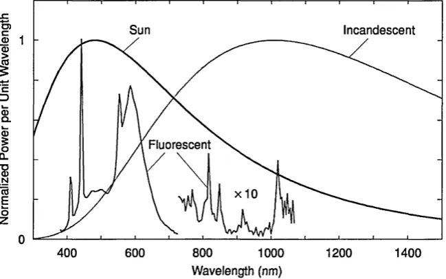
2.3 Optical power spectra of common ambient light sources
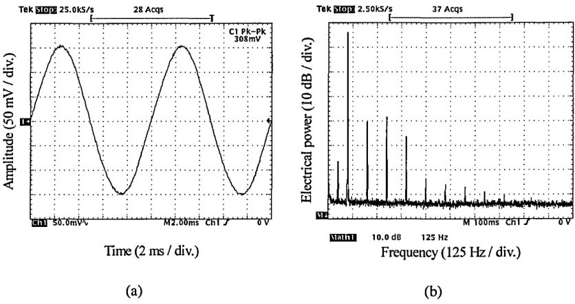
2.4(a)-(b) Incandescent bulb: (a) time domain waveform, and (b) detected electrical spectrum
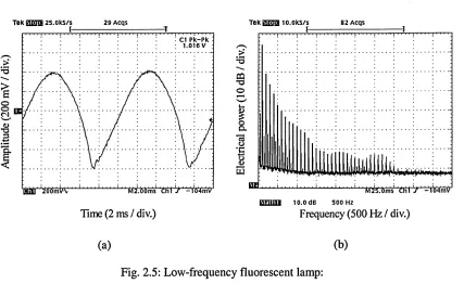
2.5(a)-(b) Low-frequency fluorescent lamp: (a) time domain waveform, and (b) detected electrical spectrum
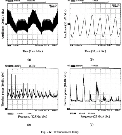
2.6(a)-(d) HF fluorescent lamp: time domain waveform: (a) low frequency component, (b) high frequency component and detected electrical spectrum: (c) low frequency component, (d) high frequency component
3.1 Basic implementation of multiple-subcarrier modulation
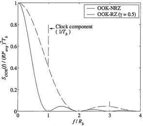
3.2(a)-(b) Transmitted waveforms for OOK: (a) NRZ, and (b) RZ (y = 0.5) 3.3 PSD of OOK-NRZ and OOK-RZ (y = 0.5)
3.4 Receiver for baseband OOK
3.5 Matched filter output for detected OOK-NRZ pulse 3.6 Maximum-likelihood sequence detector
3.7 Transmitted waveforms for 4-PPM 3.8 PSD of PPM for L = 4, 8 and 16
3.9(a)-(b) PPM receiver: (a) hard-decision, and (b) soft decision 3.10 Matched filter output for detected PPM pulse
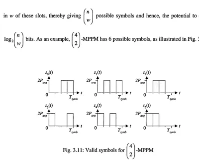
3.11 Valid symbols for ' 4 '
2
v y
-MPPM
3.12 4-DPPM symbol set
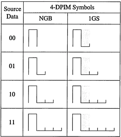
4.1 Mapping of source data to transmitted symbols for 4-DPIM(NGB) and 4-DPIM(lGS)
4.2 Normalized bandwidth requirement versus number of bits per symbol for DPIM(NGB), DPIM(IGS) and PPM
4.3 PSD of DPIM(NGB) for L = 4, 8,16 and 32 4.4 PSD of DPIM(IGS) for L = 4, 8,16 and 32
4.5(a)-(d) Types of error in DPIM: (a) Transmitted 8-DPIM(lGS) signal, (b) erasure error, (c) false alarm error, and (d) wrong slot error
4.6 PER versus probability of slot error for 16-DPIM(NGB) using various packet lengths
4.8 Block diagram of a DPIM demodulator
4.9 Using DPIM in a fixed throughput system
4.10 Matched filter output for detected DPIM pulse
4.11 Conditional probability density functions of s0 in the presence of signal
independent AWGN
4.12 Scaled conditional probability density function of s0 for P(zero) > P(one) 4.13(a)-(b) Normalized optimum threshold level versus PER: (a) DPIM(NGB), and
(b) DPIM(IGS)
4.14 Average optical power penalty incurred when using a midway threshold level versus number of bits per symbol for DPIM(NGB) and DPIM(IGS)
4.15 Normalized average optical power requirement versus normalized bandwidth requirement for various modulation techniques operating on a nondistorting AWGN channel
5. l(a)-(b) Photocurrent generated by the interference signal: (a) low frequency component, and (b) high frequency component
5.2 Block diagram of the OOK system
5.3 Normalized average optical power requirement versus bit rate for OOK with and without fluorescent light interference
5.4 Block diagram of the PPM system
5.5 Normalized average optical power requirement versus bit rate for PPM(TH) with and without fluorescent light interference
5.6 Normalized average optical power requirement versus bit rate for PPM(MAP) with and without fluorescent light interference
5.7 Block diagram of the DPIM system
5.8 Normalized average optical power requirement versus bit rate for DPIM(NGB) with and without fluorescent light interference
5.9 Normalized average optical power requirement versus bit rate for DPIM(IGS) with and without fluorescent light interference
5.10(a)-(c) 8-DPIM(lGS) sequence: (a) HPF input, (b) HPF output, and (c) matched filter output
5.1 l(a)-(b) Histogram of matched filter output for OOK with: (a) f c/R b= 10-3, and
(b) f j R b=10~2
5.12 Normalized optical power requirement versus f c/Rb for OOK
5.16(a)-(b) Histogram of matched filter output for 8-DPIM with f c/R b = 10'2 for: (a) NGB, and (b) 1GS
5.17 Normalized average optical power requirement versus f c /R b for DPIM(NGB)
5.18 Normalized average optical power requirement versus f c /Rb for DPIM( 1GS)
5.19 Normalized average optical power requirement versus normalized HPF cut-on
frequency for OOK at various bit rates
5.20 Normalized average optical power requirement versus bit rate for OOK with
fluorescent light interference and optimized high-pass filtering
5.21(a)-(d) Normalized average optical power requirement vs. normalized HPF cut-on
frequency for PPM(TH) at various bit rates with: (a) L = 4, (b) L = 8,
(c) L = 16, and (d)L = 32
5.22(a)-(d) Normalized average optical power requirement vs. normalized HPF cut-on frequency for PPM(MAP) at various bit rates with: (a) L = 4, (b) L = 8, (c) L = 16, and (d)L = 32
5.23 Normalized average optical power requirement versus bit rate for PPM(TH) with fluorescent light interference and optimized high-pass filtering
5.24 Normalized average optical power requirement versus bit rate for PPM(MAP) with fluorescent light interference and optimized high-pass filtering
5.25(a)-(d) Normalized average optical power requirement vs. normalized HPF cut-on frequency for DPIM(NGB) at various bit rates with:(a) L = 4, (b) L = 8, (c) L = 16, and (d)L = 32
5.26(a)-(d) Normalized average optical power requirement vs. normalized HPF cut-on frequency for DPIM(IGS) at various bit rates with: (a) L = 4, (b) L = 8, (c) L = 16, and (d)L = 32
5.27 Normalized average optical power requirement versus bit rate for DPIM(NGB) with fluorescent light interference and optimized high-pass filtering
5.28 Normalized average optical power requirement versus bit rate for DPIM(IGS) with fluorescent light interference and optimized high-pass filtering
6.1 Block diagram of the unequalized OOK system 6.2 Response of c* to a single one in various bit positions
6.3 Normalized average optical power requirement vs. normalized delay spread for OOK
6.4(a)-(b) Simulated eye diagrams at the receiver filter output for: (a) DT = 0.02, and (b) Dt = 0.2
6.5 Block diagram of the unequalized PPM system
6.7 Average optical power penalty versus normalized delay spread for OOK, PPM(TH) and PPM(MAP)
6.8 Block diagram of the unequalized DPIM(NGB) system
6.9 Normalized average optical power requirement versus normalized delay spread for DPIM(NGB)
6.10 Average optical power penalty versus RMS delay spread normalized to slot duration for DPIM(NGB)
6.11 Normalized average optical power requirement versus normalized delay spread for DPIM(NGB) with L - 4 and L = 32 using various threshold levels
6.12 Mapping of source data to transmitted symbols for 4-DPIM(NGB), 4-DPIM(lGS) and 4-DPIM(2GS)
6.13(a)-(d) Normalized average optical power requirement versus normalized delay spread for DPIM(NGB), DPIM(IGS) and DPIM(2GS) with: (a) L = 4, (b) L = 8, (c) L = 16, and (d)L = 32
6.14 Average optical power penalty versus normalized delay spread for DPIM(NGB), DPIM(IGS) and DPIM(2GS) with L = 4 and L = 32
6.15(a)-(b) (a) Block diagram of DPIM system with DFE, and (b) Equivalent discrete-time block diagram of DPIM system with DFE
6.16 Normalized average optical power requirement versus normalized delay spread for DPIM(NGB) with a ZF-DFE
6.17 Normalized average optical power requirement versus normalized delay spread for DPIM(NGB), DPIM(IGS), DPIM(2GS) and DPIM(NGB) with a ZF-DFE for L = 4 and L - 32
7.1 System block diagram
7.2 Position of transmitter and receiver 7.3 Position of artificial ambient light sources
7.4 SER versus average received irradiance in the presence of natural light with
f c ~ 48 kHz
7.5 SER versus average received irradiance in the presence of various artificial ambient light sources with/c ~ 48 kHz
7.6(a)-(b) Eye diagram at predetection filter output for two ambient light cases: (a) darkness, and (b) incandescent bulb without optical filter
7.7 Transmitted and received signal with/c = 100 kHz
7.8 Normalized average optical power requirement versus normalized HPF cut-on frequency (simulated)
7.9 SER versus normalized HPF cut-on frequency (measured)
7.11 SER versus average received irradiance in the presence of various artificial ambient light sources with/c ~ 884 kHz
7.12(a)-(b) Eye diagram at predetection filter output for two ambient light cases: (a) darkness, and (b) incandescent bulb without optical filter
A. 1 Possible DPIM(IGS) slot sequences resulting in a product of 1 when k = 4
A.2(a)-(d) ACF of DPIM(IGS) for: (a) L = 4, (b) L = 8, (c) L = 16, and (d) L = 32 B. 1 Transmitter block diagram
B.2 Block diagram of ‘wr_mem’ module B.3 Block diagram of ‘rd_mem’ module B .4 Schematic diagram of DPIM Modulator B.5 Optical transmitter
B.6 Receiver block diagram B.7 Optical front end B.8 Post amplifier
B.9 Peak SNR of 4th order Bessel low-pass filter (relative to matched filter case) versus normalized cut-off frequency for two different pulse shapes
B. 10 4th order Bessel low-pass filter B. 11 Threshold detector
B. 12 Threshold detector operation B. 13 Guard slot circuit
B.14 Error counter
List of Tables
2.1 Artificial ambient light sources
2.2 IB and Ipk.pk for incandescent bulb with and without optical filtering
2.3 1B and lpk.pk for low-frequency fluorescent lamp with and without optical filtering 2.4 IB and Ipk.pk for high-frequency fluorescent lamp with and without optical filtering 5.1 Low frequency component phase values
5.2 High frequency component amplitude and phase values
Contents
Abstract ii
Acknowledgements iii
Declaration iv
Glossary of Abbreviations v
Glossary of Symbols vii
List of Figures xii
List of Tables xvii
1. Introduction 1
1.1 Research Obj ectives 5
1.2 Organisation of Thesis 6
1.3 Original Contributions 8
1.4 List of Publications 10
2. Review of Indoor Optical Wireless Links 11
2.1 Introduction 11
2.2 Properties of Indoor Optical Wireless Links 12
2.3 Link Configuration 15
2.4 Review of Channel Characterisation 19
2.5 Optical Component Selection 21
2.6 Ambient Light Sources 24
2.6.1 Incandescent lamp 26
2.6.2 Fluorescent lamp driven by conventional ballast 27 2.6.3 Fluorescent lamp driven by electronic ballast 28
2.7 Summary 30
3. Review of Modulation Techniques 32
3.1 Introduction 32
3.2 On-Off Keying 36
3.2.1 Code properties 36
3.2.2 Power spectral density 37
3.2.3 Error performance on nondistorting channels 39 3.2.4 Review of error performance on multipath channels 42
3.3 Pulse Position Modulation 45
3.3.2 Power spectral density 46
3.3.3 Error performance on nondistorting channels 47
3.3.4 Review of error performance on multipath channels 51
3.3.5 Trellis-coded PPM 53
3.3.6 PPM variants 54
3.4 Summary 56
4. DPIM Code Properties 58
4.1 Introduction 58
4.2 DPIM Code Properties 59
4.3 DPIM Spectral Properties 62
4.4 Measuring the Error Performance of DPIM 66
4.5 DPIM Receiver Structure 69
4.6 Error Performance on Nondistorting Channels 72
4.6.1 DPIM with no guard band 72
4.6.2 DPIM with one guard slot 74
4.6.3 Optimum threshold level 77
4.6.4 Performance comparison 83
4.7 Summary 86
5. The Effect of Ambient Light Sources on Link Performance 88
5.1 Introduction 88
5.2 Fluorescent Lamp Model 91
5.3 The Effect of Fluorescent Light Interference Without
Electrical High-Pass Filtering 93
5.3.1 OOK 93
5.3.2 PPM 97
5.3.3 DPIM 103
5.4 The Effect of Baseline Wander Without Fluorescent Light Interference 108
5.4.1 OOK 110
5.4.2 PPM 114
5.4.3 DPIM 118
5.5 The Effect of Fluorescent Light Interference With
Electrical High-Pass Filtering 124
5.5.1 OOK 124
5.5.2 PPM 128
6. The Effect of Multipath Propagation on Link Performance 144
6.1 Introduction 144
6.2. Channel Model 145
6.3 Unequalized Performance of Various Modulation Techniques 148
6.3.1 OOK 148
6.3.2 PPM 153
6.3.3 DPIM 159
6.4 DPIM With a Guard Band 164
6.5 DPIM With Equalization 172
6.6 Summary 178
7. System Implementation 181
7.1 Introduction 181
7.2 System Overview 182
7.3 Link Setup 184
7.4 Performance of Experimental Link 186
7.4.1 Receiver not optimized for high-frequency fluorescent lamp 186 7.4.2 Receiver optimized for high-frequency fluorescent lamp 190
7.5 Summary 196
8. Conclusions 198
9. Future Work 205
Appendix A: Derivation of Slot Autocorrelation Function of DPIM(IGS) 207
Appendix B: Details of Experimental System 213
B.l Transmitter 213
B.1.1 Modulator 214
B. 1.2 Optical transmitter 218
B.2 Receiver 219
B.2.1 Optical front end 219
B.2.2 Post amplifier 222
B.2.3 Predetection filter 223
B.2.4 Threshold detector 227
B.2.5 Guard slot circuit 229
B.3 ABEL HDL and C Source Code 231
B.3.1 ABEL HDL for ‘wr_mem’ module 231
B.3.2 C source code used to fill RAM with random data 232
B.3.3 ABEL HDL for ‘rd_mem’ module 233
Chapter 1
Introduction
The emergence of portable computing devices such as laptops, palmtops and personal digital
assistants (PDAs) has fuelled the demand for mobile connectivity and hence, led to the
development of wireless local area networks (LANs). Wireless LANs offer users increased
mobility and flexibility compared with traditional wired networks, and may be classified as
either infrastructure wireless or ad hoc wireless networks [1]. Untethered from conventional
network connections, infrastructure wireless LANs allow users to maintain network
connectivity whilst roaming anywhere within the coverage area of the network. This
configuration requires the use of access points, or base stations, which are connected to the
wired LAN and act as interfaces to the wireless devices. Each access point may accommodate
multiple clients. Examples of practical applications for wireless infrastructure LANs which are
often cited include medical professionals accessing patient records, real-time vital signs and
other reference data at the patient bedside, and factory floor workers accessing part
specifications and process information as and when required. In contrast, ad hoc wireless LANs
are simple peer-to-peer networks in which each client only has access to the resources of the
administration or preconfiguration, and are created on demand only for as long as the network is
needed. Examples of practical applications for wireless ad hoc LANs include employees sharing
information during a meeting, and colleagues electronically swapping business cards.
The term wireless is synonymous with radio, and there are numerous radio LAN products on the
market today. The majority of these products operate in the industrial, scientific and medical
(ISM) band located at 2.4 GHz, which has the advantage of being licence free in most countries.
However, the available bandwidth is limited to 83.5 MHz, and must be shared with numerous
other products on the market such as cordless telephones and baby monitors. Consequently,
robust spread spectrum modulation techniques are required, which result in low data rates. As
an example, the IEEE 802.11-1997 standard for wireless LANs specifies two radio physical
layers for operation in the 2.4 GHz ISM band. These two physical layers use frequency-hopping
spread spectrum (FHSS) and direct sequence spread spectrum (DSSS), and offer maximum user
data rates of just 2 Mbit/s [2]. This was improved upon in 1999 with the ratification of
IEEE 802.lib , which adds two higher data rates of 5.5 Mbit/s and 11 Mbit/s to the DSSS
standard [3]. Many of the products currently on the market today are either based on this
standard, or the HomeRF standard, which also operates in the 2.4 GHz ISM band, and achieves
a maximum data rate of 10 Mbit/s using FHSS [4]. The next generation of radio LAN products,
which are just starting to emerge, operate in the so-called 5 GHz band, which has been allocated
solely for use by wireless LAN products. Consequently, this allows systems to be optimised in
terms of data rate and efficiency, free from the constraints associated with coexisting with other
products. There are currently two competing standards in this band, these being IEEE 802.11a
and HiperLAN2, both of which specify maximum data rates of 54 Mbit/s [5, 6]. One final radio
LAN standard worthy of a mention is Bluetooth, which is a short range, point-to-multipoint
standard for voice and data transfer, which again operates in the 2.4 GHz ISM band [7]. Whilst
standard class 2 devices have an expected operating range of just 10 metres, and a maximum
asymmetric data rate of a mere 723.2 kbit/s, the rationale behind bluetooth is low cost, allowing
with each other via ad hoc wireless networks termed piconets. Products equipped with
Bluetooth are just starting to appear on the market.
Along with radio, the term wireless is also applicable to systems which utilise other regions of
the electromagnetic spectrum, such as infrared. First proposed as a medium for short-range
wireless communication more than two decades ago [8, 9], infrared offers a number of
advantages over its radio frequency counterpart, the primary one being the abundance of
bandwidth which is currently unregulated world-wide [10]. To an extent, radio and infrared may
be viewed as complementary rather than competitive media. For example, if a wireless LAN is
required to cover a large area, where users can roam freely and remain connected to the network
at all times, then radio is the only cost-effective medium which can achieve this. If, however, a
wireless LAN is required to cover a more modest area, but deliver advanced bandwidth-hungry
multimedia network services such as video conferencing and video on demand, then infrared is
the only medium which truly has the bandwidth available to deliver this.
There are a variety of configurations which an infrared link may take, the simplest of which is
the directed line of sight (LOS) point-to-point link, as used in the home for the remote control of
electrical appliances such as televisions and audio equipment. This is the chosen configuration
for Infrared Data Association (IrDA) serial ports, which offer simple peer-to-peer networking
between portable electronic devices such as laptops, palmtops, PDAs and digital cameras. These
devices are specified to operate over a maximum range of 1 metre, and offer data rates from
9.6 kbit/s to 4 Mbit/s [11]. Whilst IrDA transceivers offer wireless connectivity at very low cost,
and have found their way into many of the portable electronic devices on the market over the
past 5 years or so, they are not widely used. One of the main reason for their lack of uptake is
convenience of use, since before products equipped with IrDA serial ports can communicate
with one another they must be in close proximity, have line of sight and be roughly aligned. In
their current form, IrDA links look destined to loose out to the Bluetooth, which is more
Exhibiting a similar behaviour to that of visible light, infrared signals are absorbed by dark
objects, diffusely reflected by light-coloured objects and directionally reflected from shiny
surfaces [12]. Such characteristics have given rise to another link configuration referred to as
diffuse, in which reflections from room boundaries are relied upon to provide coverage. This is
the chosen link configuration for the infrared physical layer of the IEEE 802.11-1997 standard,
which specifies a peak wavelength range of 850 - 950 nm, and supports data rates of 1 Mbit/s
and 2 Mbit/s [2]. Diffuse infrared links offer convenience on a par with radio, and the fact that
transmissions are confined to the room in which they originate also makes them inherently
secure. Furthermore, signal confinement also permits a potentially huge capacity per unit
volume, since the same optical carrier can be reused in adjacent rooms without the risk of
interference [10]. However, despite such offerings, diffuse infrared systems have had a very
limited impact in the market place to date, since they do not offer any improvement in data rate
over radio based products.
Although, to date, commercially available optical wireless systems have not come close to
delivering the high data rates which are potentially available from the infrared medium, the
reasons for this are more to do with cost constraints rather than any fundamental limitations of
the core technology. This is proven by the existence of experimental solid state tracked systems
which have been demonstrated operating at 155 Mbit/s [13, 14], which is significantly faster
than the latest radio LAN products that are currently emerging. Nevertheless, infrared is a
challenging medium and there are numerous considerations which must be taken into account
when designing high speed indoor infrared links. Nondirected LOS and diffuse links incur a
high optical path loss and must also contend with multipath propagation. Whilst multipath
propagation does not result in multipath fading in indoor infrared systems, since detector sizes
are huge in comparison with the wavelength, it does give rise to intersymbol interference, which
is one of the primary impairments to achieving high speed communication. In addition to this,
infrared links must be capable of operating in environments where intense ambient light levels
transmitted signal, and secondly, artificial sources of ambient light generate a periodic
interference signal, which can contain harmonics into the MHz region for fluorescent lamps
driven by electronic ballasts [15, 16]. Finally, all these factors must be overcome without
breaching eye safety regulations, which place limitations on the maximum optical transmit
power which can be used.
Within the field of indoor optical wireless communications, a considerable amount of research
has been carried out on the evaluation of modulation techniques. Whilst numerous schemes
have been proposed, each having their own advantages and disadvantages, the two modulation
techniques which have received by far the greatest attention, to date, are on-off keying (OOK)
and pulse position modulation (PPM). In this thesis another modulation technique is considered,
namely digital pulse interval modulation (DPIM). Whilst DPIM has been shown to be well
suited to optical fibre communication applications, it possesses certain characteristics which
suggest that it may also be an attractive choice for use in optical wireless communication
systems. Thus, it is the use of DPIM on indoor optical wireless links which is the main focus of
this work.
1.1 Research Objectives
The fundamental aim of the work presented in this thesis is to access the suitability of digital
pulse interval modulation as a candidate modulation scheme for indoor optical wireless
communication systems. In order to achieve this, a number of research objectives have been
identified, as outlined below:
• Review the fundamental properties of indoor optical wireless communication systems,
understand the characteristics of the indoor infrared channel, and identify the constraints
• Review the modulation schemes which have been proposed to date and identify the
important criteria. Examine OOK and PPM in detail, and understand what advantages these
schemes have over other techniques.
• Review the fundamental properties of DPIM. Investigate the spectral properties of the
scheme, and examine the effect of parameters such as the choice of threshold level and the
use of guard bands. In addition, identify any possible limitations of the scheme which may
result from its nonuniform symbol structure.
• Examine the performance of DPIM in the presence of interference from artificial sources of
ambient light. Investigate possible methods of improving the performance of the scheme,
and compare with OOK and PPM.
• Examine the performance of DPIM in the presence of intersymbol interference resulting
from multipath dispersion. Investigate the effectiveness of adding a guard band, and
compare this with more traditional equalization methods. Also compare with the
performance of OOK and PPM.
• Construct prototype diffuse optical wireless system using DPIM. Measure the error
performance of the link under various ambient light conditions, and compare with the
simulated results.
1.2 Organisation of Thesis
This thesis is divided into nine chapters. Following the introduction, chapter 2 provides a
indoor infrared channel are described, and the work done, to date, on the characterisation and
modelling of this channel is reviewed. The chapter also describes the various configurations
which indoor infrared links may take, and discusses the advantages and disadvantages of each.
The chapter ends with an examination of ambient light sources, which are a source of
degradation in indoor optical wireless communication systems.
Chapter 3 presents a review of the modulation techniques which have been considered for use in
indoor optical wireless communication systems. The chapter begins by identifying the criteria
which are important when evaluating modulation techniques for use in indoor infrared links,
and gives a brief overview of the types of schemes considered. The chapter then goes on to
focus on OOK and PPM, which are the two most widely adopted schemes to date. For each
scheme the code properties, spectral properties and error performance are reviewed. In the case
of PPM, coding schemes and variants of the technique which have also been considered for use
in indoor optical wireless communication systems are discussed.
Chapter 4 provides an introduction to DPIM. In this chapter, the basic code properties of DPIM
are described in detail, and a spectral analysis of DPIM is presented, which is based on a new
expression for the slot autocorrelation function. The chapter goes on to discuss measures of
performance for DPIM, and considers possible methods of detection. Finally, the chapter ends
with an analysis of the error performance of DPIM on nondistorting channels limited by
additive white Gaussian noise. In this analysis, the effect of adding a guard band and optimising
the threshold level are also examined. Performance comparisons are made with OOK and PPM.
In chapter 5, the error performance of DPIM is examined in the presence of interference arising
from artificial sources of ambient light. Since fluorescent lamps driven by electronic ballasts
generate interference which is potentially the most degrading, consideration is limited to this
type of source. The chapter also analyses the effectiveness of electrical high-pass filtering in
which is introduced by the high-pass filter. Throughout the chapter, analysis is also carried out
for OOK and PPM, and the various modulation techniques are compared.
In chapter 6, the error performance of DPIM is analysed in the presence of intersymbol
interference (ISI) arising from multipath propagation. After considering the unequalized
performance of DPIM, the chapter goes on to investigate the effectiveness of adding a guard
band to each DPIM symbol in order to mitigate the effect of the ISI. In order to quantify the
effectiveness of the guard band, the performance of DPIM using a zero forcing decision
feedback equalizer is then analysed, which is a more conventional approach to combating the
effects of ISI. Again, similar analysis is also carried out in the chapter for OOK and PPM, and
the various schemes are compared.
Chapter 7 describes the design of a prototype diffuse infrared link employing DPIM. The error
performance of the prototype link was measured under a variety of ambient light conditions, and
these results are also presented in the chapter.
In chapter 8, concluding remarks are made, and the major contributions of this thesis are
outlined.
Finally, chapter 9 discusses possible areas where this work may be continued.
1.3 Original Contributions
During the course of this work, the author has:
1. Analysed the performance of DPIM on nondistorting AWGN channels. In chapter 4, using
bandwidth when a simple threshold-detection based receiver is used. Additionally, the effect
of adding a guard band to each symbol and adjusting the threshold level were also
investigated.
2. Derived a new expression for the slot autocorrelation function of DPIM using a single guard
slot, and used this to determine the power spectral density of the scheme. From the analysis
presented in chapter 4, it is apparent that DPIM has a nonzero DC component, and the
addition of a guard band to each symbol was found to have little effect on the overall
spectral profile of the scheme.
3. Investigated the performance of DPIM in the presence of interference from a fluorescent
lamp driven by a high frequency ballast. The effectiveness of electrical high-pass filtering
as a means of mitigating the interference was also investigated in chapter 5, which included
an analysis of DPIM in the presence of baseline wander which is introduced by the high-
pass filter. Optimum high-pass filter cut-on frequencies were also determined.
4. Investigated the unequalized performance of DPIM on multipath channels. In chapter 6, the
effectiveness of adding a guard band consisting of one and two guard slots in order to
mitigate the intersymbol interference was also investigated. Additionally, in order to
quantify the findings, the performance of DPIM using a ZF-DFE was analysed.
5. Developed a low bit rate prototype diffuse infrared system employing DPIM, which is
described in chapter 7. The error performance of the system was measured in the presence
of various artificial ambient light sources, and effect of electrical high-pass filtering in
1.4 List of Publications
The work presented in this thesis has resulted in the following publications, which are listed in
reverse chronological order.
1. Z. Ghassemlooy, A. R. Hayes and N. L. Seed, "The Effect of Multipath Propagation on the
Performance of DPIM in Diffuse Optical Wireless Communications," in Proceedings of IASTED International Conference on Wireless and Optical Communications, Banff, Canada, 27-29 June 2001, pp. 166-172.
2. A. R. Hayes, Z. Ghassemlooy, N. L. Seed and R. McLaughlin, “Baseline-wander effects on systems employing digital pulse interval modulation,” IEE Proceedings - Optoelectronics, vol. 147, no. 4, pp. 295-300, August 2000.
3. A. R. Hayes, Z. Ghassemlooy and N. L. Seed, “The performance of digital pulse interval modulation in the presence of multipath propagation,” in Proceedings o f 2nd International Symposium on Communication Systems Networks and Digital Signal Processing,
Bournemouth University, U.K., 18-20 July 2000, pp. 141-146.
4. Z. Ghassemlooy and A. R. Hayes, “Digital pulse interval modulation for IR communication systems - a review,” International Journal of Communication Systems, vol. 13, no. 7 & 8, pp. 519-536, November-December 2000.
5. A. R. Hayes, Z. Ghassemlooy and N. L. Seed, “The effect of baseline wander on the performance of digital pulse interval modulation,” in Proceedings o f IEE Colloquium on Optical Wireless Communications, London, U.K., 22 June 1999, pp. 13/1-13/5.
6. A. R. Hayes, Z. Ghassemlooy and N L Seed, “Indoor optical wireless communication using digital pulse interval modulation,” poster presented at SET'99, House of Commons, London, U.K., 15 March 1999.
7. Z. Ghassemlooy, A. R. Hayes, N. L. Seed and E. D. Kaluarachchi, “Digital pulse interval modulation for optical communications,” IEEE Communications Magazine, vol. 36, no. 12, pp. 95-99, December 1998.
8. A. R. Hayes, Z. Ghassemlooy and N. L. Seed, “Optical wireless communication using digital pulse interval modulation,” in Proceedings of SP1E Conference on Optical Wireless Communications, Boston, U.S.A., 5 November 1998, vol. 3532, pp. 61-69.
9. Z. Ghassemlooy, A. R. Hayes, N. L. Seed and E. D. Kaluarachchi, “Digital pulse interval modulation for optical wireless communications,” in Proceedings o f 3rd Iranian Academic Association Annual Conference on Computers and Communications, New York, U.S.A.,
Chapter 2
Review of Indoor Optical Wireless
Links
2.1 Introduction
This chapter aims to provide a general introduction to indoor optical wireless links. In section
2.2, the unique properties of indoor optical wireless links are reviewed, and the constraints
imposed on system design are highlighted. Indoor optical wireless links can be configured in a
variety of ways, each suitable for different applications. In section 2.3, the various
configurations are described, and their advantages and disadvantages discussed. In order to
achieve efficient link design, it is imperative that the characteristics of the channel are well
understood. A considerable amount of work has been published on channel characterisation,
covering both experimental measurement and computer modelling. This work is reviewed in
section 2.4. There are a number of considerations which must be taken into account when
selecting the optical components of a system. These considerations are discussed in section 2.5.
natural and artificial sources. These ambient light sources are discussed in section 2.6, and
measurements taken of various sources are presented. Finally, the chapter is summarised in
section 2.7.
2.2 Properties of Indoor Optical Wireless Links
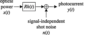
For low-cost optical wireless communication systems, intensity modulation with direct
detection (IM/DD) is the only feasible method of communication [10]. In this mode of
operation, the intensity or power of the optical source x(t) is directly modulated by varying the
drive current. At the receiver, a photodetector is used to generate a photocurrent y(r), which is
proportional to the instantaneous optical power incident upon it. An optical wireless system
using IM/DD has an equivalent baseband model which hides the high-frequency nature of the
optical carrier [12]. This model is illustrated in Fig. 2.1 [10], in which R is the photodetector
responsivity and h{t) is the linear baseband channel impulse response.
optical power ■
x(t) Rh{t)
^ photocurrent
y(t)
signal-independent shot noise
[image:37.612.207.385.433.507.2]n(t)
Fig. 2.1: Equivalent baseband model of an optical wireless system using IM/DD
As with radio systems, indoor optical wireless links are subject to multipath propagation, which
is most pronounced in links using nondirectional transmitters and receivers. For both systems,
multipath propagation causes the received electric field to undergo severe amplitude fades on
the scale of a wavelength, and consequently, a detector smaller than one wavelength would
experience multipath fading. However, infrared wireless receivers have detector areas which are
provides an inherent spatial diversity, thus preventing multipath fading [10]. Whilst indoor
infrared links are not susceptible to multipath fading, multipath propagation does lead to
dispersion, which is modelled as a linear baseband channel impulse response h(t). Linearity
follows from the fact that the received signal is comprised of multiple spatial modes [10]. The
channel is fixed for a given position of the transmitter, receiver and intervening reflectors, and
changes significantly only when any of these are moved by distances in the order of centimetres.
Due to the high bit rates under consideration and the relatively slow movement of people and
objects within a room, the channel will vary significantly only on the time scale of many bit
periods, and therefore may be considered to be time invariant.
Infrared wireless transceivers will usually operate in environments containing an intense amount
of ambient light, emanating from both natural (solar) and artificial sources. The average
combined power of this background radiation generates a DC photocurrent IB in the
photodetector, giving rise to shot noise n(t), which has a single-sided power spectral density N0,
given as [17]:
N 0 = 2qlB, (2.1)
where q is the electron charge. Even when optical filtering is used to reject out of band light
sources, the received signal power is much lower than the power from ambient light sources
(typically 25 dB lower [10]). Consequently, IB is much larger than the maximum photocurrent
generated by the signal, and hence, the shot noise may be regarded as white, Gaussian and
independent of the received signal [18]. In the presence of intense ambient light, which is
usually the case, shot noise is the dominant noise source in a typical diffuse receiver [10]. Note
that, if little or no ambient light is present, the dominant noise source is receiver preamplifier
noise, which is also signal independent and Gaussian [12]. In addition to contributing to the
generation of shot noise, artificial ambient light sources also generate a periodic interference
signal, which must be added to n(t). Ambient light sources are discussed in more detail in
The equivalent baseband model of an optical wireless link, as illustrated in Fig. 2.1, can be
summarised by [12]:
y(t) = Rx(t) ® h(t) + n(t), (2.2)
where R is the photodetector responsivity and the symbol “®” denotes convolution. Simply
stated, the received photocurrent y(t) is the convolution of the transmitted optical power x{t)
with the channel impulse response h(t), scaled by the photodetector responsivity R, plus an
additive noise n{t). Whilst (2.2) is simply a linear filter channel with additive noise, optical
wireless systems differ from conventional electrical or radio systems since xit) represents power
rather than amplitude. This places two constraints on the transmitted signal. Firstly, x(t) must be
non-negative, i.e.
Secondly, eye safety requirements limit the maximum optical transmit power which may be
employed. Generally, it is the average power requirement which is the most restrictive and
hence, the average value of x(t) must not exceed a specified value Pmax, i.e. [10]:
channels when x(t) represents amplitude.
These differences have a profound effect on system design. On conventional channels, the
signal to noise ratio (SNR) is proportional to the average received power, whereas on optical
x(t) > 0. (2.3)
max (2.4)
implying that relatively high optical transmit powers are required, and only a limited path loss
can be tolerated. The fact that the average optical transmit power is limited, suggests that
modulation techniques possessing a high peak-to-mean power ratio are favourable. This is
generally achieved by trading off power efficiency against bandwidth efficiency. When shot
noise is dominant, the SNR is also proportional to the photodetector area. Thus, single element
receivers favour the use of large area detectors. However, as the detector area increases so does
its capacitance, which has a limiting effect on receiver bandwidth. This is in direct conflict with
the increased bandwidth requirement associated with power efficient modulation techniques,
and hence, a trade off exists between these two factors.
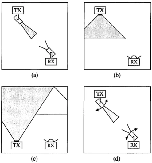
2.3 Link Configuration
Indoor optical wireless links may be configured in a variety of ways to support a multitude of
applications. Street et. al. [19] grouped these into four generic system configurations, these
being: directed LOS, nondirected LOS, diffuse and tracked, as illustrated in Fig. 2.2.
TX
RX
(a)
TX
RX
(b)
TX
RX
(d)
TX RX
[image:40.613.170.418.448.713.2](C)
The directed LOS configuration, illustrated in Fig. 2.2(a), achieves a high power efficiency by
utilising narrow beam transmitters and narrow field of view (FOV) receivers. The use of narrow
FOV receivers allows optical concentrators to be employed along with thin film optical filters,
since the angular dependence of the filter response does not pose a problem. Furthermore,
directed LOS systems do not suffer from multipath propagation, and ambient background light
is largely rejected. Thus, the potential data rate is limited only by the available power budget
rather than multipath dispersion [20]. However, directed LOS links must be pointed prior to use,
and require an uninterrupted line of sight path between the transmitter and receiver, thus making
them susceptible to blocking. In addition to this, by their very nature, they are more suited to
point-to-point links rather than point-to-multipoint broadcast type links, thus reducing their
flexibility. Directed LOS is the most well known link topology, and has been used for many
years in low bit rate, simplex remote control applications for domestic electrical equipment,
such as televisions and audio equipment. Additionally, directed LOS is the chosen configuration
for IrDA links [11]. A number of experimental links using the directed LOS configuration have
been reported [21-23], along with a demonstration of an IEEE 1394 multimedia home network
[24].
The nondirected LOS configuration, illustrated in Fig. 2.2(b), uses wide beam transmitters and
wide FOV receivers to achieve an increased coverage area and alleviate the need for pointing.
Compared with the directed LOS configuration, these benefits are achieved at the expense of a
reduced irradiance, for a given range and transmit power. The use of wide angle transmitters
and receivers means that a portion of the received signal may have undergone one or more
reflections from walls and room objects, thus giving rise to multipath propagation. Additionally,
since the majority of power incident on the photodetector is due to the LOS path, nondirected
LOS links are still prone to blocking. Nondirected LOS links are well suited to point-to-
multipoint broadcast type applications. A typical scenario for this link topology would be an
of accurately defining the coverage area of nondirected LOS links [25]. By controlling the
coverage area, large rooms may be divided into ‘optical cells’, each serviced by a different
infrared access port. Such an architecture has been used in experimental systems [26, 27] and
proposed for a number of practical applications including telepoints [28], trading desks [29] and
desk area networks [30]. An example of a commercial nondirected LOS system is VIPSLAN-10
manufactured by JVC [31]. The system generates a cell radius of up to 10 m, and offers a data
rate of 10 Mbit/s, which is shared between the users operating within the cell.
The diffuse configuration, illustrated in Fig. 2.2(c), was first proposed in 1978 by Gfeller and
Bapst [8, 9]. Typically, a diffuse transmitter points vertically upwards towards the ceiling,
emitting a wide beam of infrared energy. The receiver has a wide FOV, and collects the signal
after it has undergone one or more reflections from the ceiling, walls and room objects.
Measurements to determine the reflection coefficient for a variety of materials commonly used
in indoor environments were carried out by Gfeller and Bapst [9]. Reflection coefficients were
found to range from 0.4 to 0.9, with white plaster walls varying between 0.7 and 0.85 depending
on surface texture and angle of incidence. From a users point of view, the diffuse link topology
is the most convenient since it does not require any pointing of the transmitter or receiver, nor
does it require a LOS path to be maintained. In addition to this, the configuration is also
extremely flexible, and can be used for both infrastructure and ad hoc networks [19]. However,
along with nondirected LOS links, diffuse links incur a high optical path loss, which is typically
50-70dB for a horizontal separation distance of up to 5 m [32]. The path loss is increased
further if a person is standing next to the receiver such that the main signal path is obstructed, a
situation referred to as shadowing. In addition to this, diffuse links must also contend with
severe multipath propagation. Intersymbol interference limits the maximum unequalized bit rate
to -260 Mbitm/s [9]. Thus, for a coverage volume of 10 x 10 x 3 m, the unequalized bit rate
would be limited to -16 Mbit/s [25]. Nevertheless, to date, the diffuse configuration has
received the greatest interest from the research community, and the a number of experimental
diffuse links have been reported covering bit rates up to 50 Mbit/s [33-41]. Diffuse is also the
systems are now commercially available. An example of a commercial diffuse system is the
wireless network manufactured by Spectrix Corporation [42]. The system is specified to work
over a coverage area of 1000 square feet, and achieves a data rate of 4 Mbit/s, which is shared
between all the users within the cell.
For nondirected LOS and diffuse links, rather than using a single element detector, significant
performance improvements can be achieved using an angle-diversity receiver, which may be
implemented in one of two ways. A non-imaging angle-diversity implementation consists of
multiple receiving elements that are oriented in a different directions, each element having its
own nonimaging concentrator. The main drawback of this approach is that it can lead to an
excessively bulky and costly receiver. A more elegant implementation is the imaging angle-
diversity receiver, the so called ‘fly-eye receiver’ first proposed by Yun and Kavehrad [43],
which consists of an imaging optical concentrator (e.g. a lens) with a segmented photodetector
array placed at its focal plane. Regardless of the implementation method, the photocurrent
generated by each element is amplified separately and may then be processed in a variety of
ways, which vary in terms of performance and complexity. Angle-diversity receivers can
simultaneously achieve a high optical gain and a wide field of view. By exploiting the fact that
unwanted signals are generally received from different directions to that of the desired signal,
they can significantly reduce the effects of ambient light noise, co-channel interference and
multipath distortion [44]. The performance gains achieved by angle-diversity receivers have
been analysed in [45-51]. A further improvement in the power efficiency of diffuse links can be
achieved by replacing the single wide-beam diffuse transmitter with a multi-beam transmitter,
sometimes referred to as a quasi-diffuse transmitter, which consists of multiple narrow beams
pointing in different directions [43]. The performance of diffuse links using multi-beam
transmitters and angle-diversity receivers is presented in [43, 44, 52-56]. Details of an
experimental 70 Mbit/s link using a multi-beam transmitter and an angle-diversity receiver are
The final configuration is the tracked system, illustrated in Fig. 2.2(d), which offers the high
power efficiency and potentially high bit rates of directed LOS links, with the increased
coverage enjoyed by nondirected LOS systems. In an early experimental tracked system
developed by B.T. Labs, which achieved a bit rate of 1 Gbit/s, the tracking was performed using
mechanical steerable optics [57]. However, mechanical steerable optics are prohibitively
expensive and difficult to miniaturise. Consequently, in the same paper, Wisely et. al. proposed
a solid state tracked system, using multi-element transmitter and receiver arrays along with a
lens arrangement. Using this arrangement, steering is merely a matter of selecting the
appropriate array element. Conceptually, this is similar to the angle-diversity receiver discussed
earlier. Solid state tracked systems are analysed in [58, 59], and experimental systems achieving
data rates of 34 Mbit/s [60], 100 Mbit/s [61] and 155Mbit/s [13, 14] have been demonstrated.
Note that, along with diffuse links using multi-beam transmitters and angle-diversity receivers,
tracked systems offer the potential to implement space-division multiplexing, whereby multiple
users can communicate without suffering a loss of per-user capacity, since each user is located
in a different cell.
2.4 Review of Channel Characterisation
Detailed characterisation of the indoor optical wireless channel is essential for effective link
design. The power penalties directly associated with the channel may be separated into two
factors, these being optical path loss and multipath dispersion [62, 63]. For directed LOS and
tracked configurations, reflections do not need to be taken into consideration, and consequently
the path loss is easily calculated from knowledge of the transmitter beam divergence, receiver
size and separation distance. For nondirected LOS and diffuse links, the optical path loss is
more complex to predict, since it is dependent on a multitude of factors, such as room
dimensions, the reflectivity of the ceiling, walls and objects within the room, and the position
loss for nondirected LOS and diffuse links, it is necessary to analyse the distribution of optical
power for a given setup.
Gfeller and Bapst [8] studied the power distribution for diffuse links, basing their model on
single reflections only. The authors showed that by using an optical source consisting of
multiple elements oriented in different directions, a more uniform coverage can be obtained
over a larger area, compared with a single wide-beam optical source. Lomba et. al. [64]
addressed the optimization of the optical power distribution for diffuse and nondirected LOS
links. Based on this work, the authors proposed a specification for the emitter radiation pattern
(ERP) of the IEEE 802.11 infrared physical layer standard [2, 65]. Pakravan and Kavehrad [66]
also analysed the optical power distribution for a typical conference room using various link
configurations. For nondirected LOS links, as an alternative to adjusting the ERP, several
researches have considered using a grid of ceiling mounted t