ISSN: 1816-949X
© Medwell Journals, 2019
Performance Analysis of PLC with Turbo Code and OFDM by Sending Image
1
Shahad W. Al-Amari and
2Kasim K. Abdalla
1, 2
Department of Electrical Engineering, College of Engineering, University of Babylon, Hillah
Babylon, Iraq
Abstract: Performinga Power Line Communication (PLC) analysis has been presented in this study. PLC
technology enables the transmission of data through the electrical supply network. Since, the power line is designed for the distribution of power, it is not a good way for the purpose of communication and there is a need for advanced methods of communication for effective communication across the channel. At performing a PLC Model, there are many important considerations that the PLC communication is affected with such as nature of channel and the noise interference, therefore, the model consists of a power line model and a noise model. The PLC Model has been presented Orthogonal Frequency Division Multiplexing (OFDM) transceiver system integrated with 8-Quadrature Amplitude Modulation (8-QAM) and turbo code. Sending a picture over a channel can be represented as sending a large of data. Hence,the system simulations of this research are achieved by sending colored pictures over the proposed PLC channel. Also, the system is performed sending colored picture over Additive White Gaussian Noise (AWGN) channel simulation for different Signal to Noise Ratio (SNR). The simulation results which are achieved by MATLAB program show good performance of the system that consists of the power line and noise channel model.
Key words:Power line channel, turbo code, orthogonal frequency division multiplexing, QAM, noise, AWGN,
SNR
INTRODUCTION
Power lines are used as a Power Line Communication (PLC) technologys where carries data of information on a conductor that is moreover utilized at the same time to distribute electricity to consumers or to transfer AC power, therefore, power line communication technology’s by the benefit of not needing any additional wires can be taken profits which is also called power line carrier (Mlynek et al., 2010a, b).
It can provide the cost of infrastructure in fiber optic cable composition and can arrive in rustic areas where the infrastructure of power line already exists. The transmission of information, video and pictures via. Power Line Channels (PLC) is not only the interest of researchers but also of consumers. PLCs offers simple to use services and the flexibility, for example, fast and secure web browsing and strong dial-up internet access that delivers good voice quality. Moreover, PLC which meets high-speed data transfer requirements can support high transmission rates of 200 Mbps (Al-Hinai et al., 2009).
Generally, through the use of this technology, there are more shortcomings. The useful signal interference, supplies of energy network and a smaller range of useful signal are fundamental (Mlynek et al., 2010a, b). The
systems of PLC are located into two regions: narrowband PLC and broadband PLC. Firstly, narrowband PLC is mainly utilized to particular services including management of power consumption centralized, induction, reading of remote meter, driving, etc., maximum frequency which narrowband technology operates at it is 150 kHz and its bit rate theoretical is at kilobytes (up to 2 Mbit/sec). Second, broadband PLC accomplishes the broadband communication features, allowing, for instance, quick Internet arrival or application of small LANs. The technology of the broadband operates in the frequency band from 150 kHz to 34 MHz. The latest development is that possible to use power network as well as the systems of narrowband PLC (Mlynek et al., 2011).
Advanced modulation technique like Orthogonal Frequency Division Multiplexing (OFDM) and Forward Error Correction (FEC) schemes like turbo coding can be used to improve the BER performance.
In this study has been analyzed and simulated the model of noise in PLC systems through sending and receiving a picture via. turbo code and OFDM by using Simulink/MATLAB program, also discussed different parts of PLC. The kind of PLC was then analyzed as an environment of communication.
Encoder In-put Turbo code Out-put Data Decoder M-QAM IFFT de-QAM FFT Channel OFDM Data
Fig. 1: The PLC communication basic model with OFDM and turbo code system
MATERIALS AND METHODS
System description: The three basic elements of the PLC
are transmitter, receiver and transmission line which is represented by the channel. Figure 1 shows the PLC communication basic model with OFDM and Turbo code system. The transmitter and receiver in this work are used turbo coding which works efficiently with low SNR compared to other coding techniques (Geethu and Narayanan, 2015a, b) and OFDM has been performed through various sub-carrier configurations. In order to be able to analyze the overall system, the discussion for all sections of the PLC system has been introduced.
OFDM system: One of Multi-Carrier Modulation
(MCM) is Orthogonal Frequency Division Multiplexing (OFDM) methods that transfer signals over multiple carriers. These carriers (subcarriers) have unique occurrences and they are orthogonal to each other. OFDM systems have been helpful in both wired (known Discrete Multi-Tone DMT) and wireless communications (known complex transmission) (Li et al., 2018).
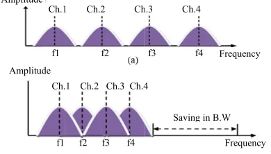
A spectral efficiency of frequency division multiplexing is extremely low as distances are large enough to ensure non-overlapping spectra. To carry various bits of a single higher rate data signal, Multi Carrier Modulation (MCM) or Multi Tone Modulation (MTM) system uses multiple carriers. In this MCM system, each channel is the path of a low rate signal and therefore, less prone to interference between the symbols, unlike a single system carrier case.
[image:2.612.96.292.102.184.2]OFDM is a DMT system, creating for modulation usingInverse Fast Fourier Transform (IFFT) and for demodulation using Fast Fourier Transform (FFT). Input information is collected in N complex numbers block, must be taken into account one per channel. On this block, IFFT is executed and the result is sent sequentially. In receiver, to retrieve the information, FFT block wise is performed. As FFT is efficient of computationally, a popular modulation OFDM is a scheme in a communication system of high speed. OFDM with Forward Error Correction (FEC) is for wireless data transmission the suitables cheme-quickly and accurately
Fig. 2: Signal spectrum of multicarrier system, (a) Non-overlapped signal spectrum and overlapped signal spectrum
(Mlynek et al., 2011). Turbo Coded OFDM (TCOFDM) system joins with turbo code good features of OFDM (Savitha and Kulkarni, 2010). One of the main OFDM components is the Cyclic Prefix (CP) used to minimize Inter-Channel Interference (ICI) and Inter-Symbol-Interference (ISI) in multipath channels. Another characteristic of OFDM is that it effectively benefits from limited bandwidth by dividing information and making IFFT on symbols that are loaded in multiple orthogonal subcarriers as shown in Fig. 2. The separate time indication of signal after IFFT is (Mlynek et al., 2010 a, b): (1)
c c c N2 1 j2πk
N N 2 n c 1
d n D(k)e
N
where, n 0[!Nc/2] and Nc is the sub-channel total numbers. Ina receiver side, opposite procedure shappen where receiver determining carrier datawhich is modulated on and decodes information via. an FFT operation and demaper (Al-Hinai et al., 2009).
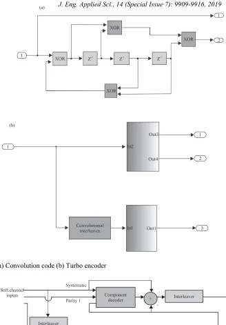
Turbo codes: To improve the BER performance of the
power-line system, so as to obtain high bit error performance at lower values of SNR, the error correcting code is used. Anyway, the power-line channel is affected by impulsive noise and multipath effects which degrade the system performance. Hence, an efficient error correction scheme, namely the turbo error correcting code has been proposed to overcome the channel effects (Anusuya and Jothimani, 2016; Geethu and Narayanan, 2015a, b; Sanchez-Martínez et al., 2010). By Berrou, Glavieux and Thitimajshima, the turbo codes were presented at first. The turbo codes iterative attribute helps to reach a large encoding gain for an uncoded system. It utilized two or more parallel or concatenated codes on variousoriginal information interleaved versions. Until the best results are achieved by decoders exchange soft decisions rather than hard decisions, the typical turbo
Amplitude Ch. Ch.1 Amplitude f1 f1
1 Ch.2 Ch.3 Ch.4 1 Ch.2 Ch
f2 f3 f4 f2
Saving in B.W 4
h.3 Ch.4
F f3 f4
W
1
XOR Z-1 Z-1 Z-1
XOR
XOR
1
2 (a)
1
1
2
3 In2
Out3
Out4
Convolutional
interleaver In1 Out1 (b)
XOR
Soft channel inputs
Systematic
Parity 1
Component decoder
Component decoder Interleaver
Interleaver
De-interleaver
De-interleaver Hard decision +
-+
-Parity 2
[image:3.612.103.431.72.543.2]Fig. 3: a) Convolution code (b) Turbo encoder
Fig. 4: Turbo decoder
encoder uses Parallel Concatenated Convolutional Codes (PCCC) where data bits are coded by two or more Recursive Systematic Convolutional Coders (RSC) as seen in Fig. 3a, each with input as interleaved versions of data as illustrated in Fig. 3b. A turbo system consists of two decoders, the first decisions of decoder are taken as
[image:3.612.105.440.473.631.2]A1 coupling interface, parallel fraction A2 coupling interface, parallel fraction A3 coupling interface, parallel fraction A4 coupling interface, parallel fraction Zs Vs Zl
The turbo codes combinations with the transmission of OFDM, called TCOFDM, can outcome in considerable refinements in terms of lower requirements for information transfer energy (Savitha and Kulkarni, 2010).
Power lines transmission system: The use of existing
power line networks is the essential rule of power lines communication for communication purposes. Through the years, power line networks have been filled as a means of transmitting and distributing signals of electricity. Up to this point, communication across power lines was limited to low-speed functions for instance, telemetry and process management that served power requirements supply tools. This restricted power line functions range has lately changed, due to huge demand for high-speed communications of broadband multimedia.
Transfer function of power line: The network of power
line which isn’t intended for its original data communications design in some likeness with other networks of wired such as telephone local loop and Ethernet. The channel modeling of power line task is difficult because its nature is random in nature with frequency and day time, geographical location and environment of rural. The chief parameters were taken into account in the noise, impedance and attenuation. The absolute power distribution impedance the system up to 30 MHz was carefully studied in many countries. The model of the component can be expressed by the F matrix illustrated in Eq. 2:
(2)
1 2
1 2
V A B V
I C D I
Where:
1γ : The coefficients of the F matrix A, B, C, D : V1, I1 Voltage and current of the input V2, I2 : Voltage and current of the output
All transactions are uniquely defined from the equivalent circuit model and transactions can be reported as model transactions for the component model using two executable models. All parameters can be calculated by the Eq. 3-7 (Anusuya and Jothimani, 2016).
(3) Acosh( l)
(4) BZ. sinh ( l)
(5) Sinh( l) C z (6) Dcosh ( l)
Hence, the transfer function can be given as:
(7)
1
1 1 s
R H
A .R B + C.R . D.R
[image:4.612.318.512.102.155.2]
Fig. 5: Cascade power line Where:
γ : The power line propagation constant. R1, Rs : The load and source power line
Resistance and l is number of the focus node on the receiving or transmitting side (Mlynek et al., 2010a, b.
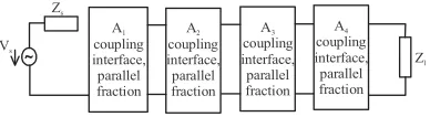
Power line modeling: The model of power line is desired
to simulate communications PLC. Apply the methods of power line utilized for distribution networks model of modeling electricity. String parameter matrices that describe the relationship between the inputs, output and current, voltage of the two-port network can be utilized to modeling the power line channel transfer function (Mlynek et al., 2010a, b ). The typical power line of the dual-port core network allows working with primary networks, two ports which can be described by cascading parameters. The cascade solution provides the ability to choose a certain degree of complexity and accuracy in the designed font. Individual blocks can also be defined as macro models that describe a data channel (Mlynek et al., 2010a, b). Figure 5 shows an example of successive dual-port networks.
The description of each part of the line is specified by a separate cascade matrix A1 to A4. Internal series impedance Zs of signal source Vs and load parallel impedance Zl can also be described by the cascading parameters which are included in the transfer function of the result. The resulting cascade matrix can be configured from source to load by applying chain rule:
n
i l
A
A
i
It is given a transfer function to the appropriate two-port network by the equation:
L s
H V V
Asynchrodous impulsive noise
Sources of interference
Asynchrodous impulsive noise
Narrow-band noise Colored
background noise
N(t)-noise (interferning random process) N(f)-transmission channel function
Transmission s(t) H(f) r(t) Receiver
Transmission channel as linesr ?lter Periodic rectangular signal
Spectral colouring
Filter White noise
Synchronous impulsive noise The transferred signal reaches receiver via. signal
path N. In path i, the arriving signal is delayed at τi time and the complex attenuation factor attenuates Ci. Attenuated pulses sum of Dirac and delay can be written for the channel impulse response h(t) (Mlynek et al., 2010 a, b; Kevin and Ajmera, 2015):
(10)
2 iN N
i 1 i 1
j f
h t δ t τ H f C e
Ci i
iFrom the power line model transfer function, the filter coefficient and the channel of the power line are calculated as a digital filter.
Interference sources and noise models: In addition to
have a transfer characteristic of the power line, it is necessary to identify potential interference sources because the power line has significant signal attenuation, interference and noise. Thus, the transmission of information contains a high error rate without any verification algorithm. The main influence on the transmission of data across power lines is the negative characteristics of power networks. These points are summarized as follows:
C Mismatched impedance
C Attenuation on the communication channel
C Interference (noise)
C Interference changing in time
For more explanation, Four different noise types have been described in this work (Mlynek et al., 2010a, b):
Background noise: It exists in a network each time. This
occurs because noise multiple sources are assembling with low power. It can be qualifiedby Power Spectral Density (PSD) which decreases with increasing frequency. Power noise density in the background can be illustrated with the equation as written below:
(11)
0 0
f A(f ) A A .e
f
Where:
A4 : The power density of f64 and
A0 : Differences between A(0) and A(4)
This model allows the background noise to be reproduced as a white noise process which obtains spectral coloring by a filter.
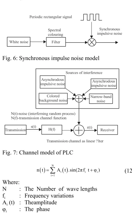
Narrow-band noise: Initial noise is generated by the
[image:5.612.311.536.83.457.2]transmission stations that transfer it within a long, middle a range of short wave. Bydependence on time and place can be changed amplitude. Narrow band noise can be modeled as anamount of multiple sine noise with different amplitude:
[image:5.612.321.520.103.165.2]Fig. 6: Synchronous impulse noise model
Fig. 7: Channel model of PLC
(12)
N i
i i 1n t A t .sin(2πf t φ)
i Where:
N : The Number of wave lengths fi : Frequency variations
Ai (t) : Theamplitude
φi : The phase
The capacitance of Ai (t) is constant in the simplest case but can arise from radio broadcasting. The phase φi is generated randomly from the interval [0, 2
π].
Asynchronous impulsive noise: The type of noise is
described by short and high voltage spikes with length 10-100 μsec. These spikes can reach a 2 kV level. This noise is the switching equipment cause in the distribution network. These noise types are considered as part of background noise.
Synchronous impulsive noise: This type results by
Uint8
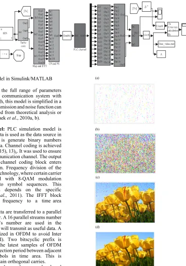
Fig. 8: System circuit model in Simulink/MATLAB This model captures the full range of parameters necessary for a form of communication system with similar properties, although, this model is simplified in a schematic figure. The transmission and noise function can be estimated either derived from theoretical analysis or from measurements (Mlynek et al., 2010a, b).
Simulation circuit model: PLC simulation model is
shown in Fig. 8. Image data is used as the data source in the proposed model. It is generate binary numbers accordingto the image data. Channel coding is achieved by the turbo code (4, (13, 15), 13)8. It was used to ensure data transmission in communication channel. The output data serial stream from channel coding block enters frequency division system. Frequency division of the spectrum is used OFDM technology, where certain carrier frequencies are mapped with 8-QAM modulation which is converted to symbol sequences. This distribution of symbols depends on the specific modulation (Mlynek et al., 2011). The IFFT block transfers data from a frequency to a time area (Mlynek et al., 2010a, b).
By using IFFT the data are transferred to a parallel stream in the S/P converter. A 16 parallel streams number that matches to carrier’s number are used in the simulation. These carriers will transmit as useful data. A protection interval is utilized in OFDM to avoid Inter Symbol Interference (ISI). Two bitscyclic prefix is generated by a few of the latest samples of OFDM symbols. CP creates a protection period between adjacent transferred OFDM symbols in time area. This is considered a way to maintain orthogonal carries.
In the simulation, background, narrow band and impulsive noises are used to model thechannel as shown in Fig. 7. In the receiver side, the transmitted data is demodulated and decoded in reverse direction.
RESULTS AND DISCUSSION
Figure 9 shows the simulation results of transmitted colored image over AWGN channel for different SNR. Normally, when the SNR has increased a good picture
Fig. 9(a-d): Sending image in AWGN channel with different SNR
will appear. As shown in Fig. 9 a-d, the best picture is presented in d which has the largest SNR. Another simulation has been done in this work by sending the same colored picture over power line model with noise model. The simulation shows that the sending image
(a)
(c)
(d) (b) )
)
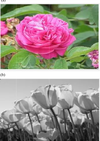
Fig. 10: Sending image through PLC channel
Fig. 11: Sending picture through PLC channel (a) and Colored (b) Gray
through PLC channel is equivalent to or better than the picture over AWGN channel with high SNR as seen in Fig. 9 and 10 d, respectively. Also, the PLC modeling system shows good performance for sending another colored as large details and gray as small details pictures as presented in Fig. 11 a, b.
CONCLUSION
Recently, PLC technologies have many useful applications such as the control application, widely used
in home automation, auto application and internet access. In this study, thetransmission channel and source of interference are described to simulate PLC communications. The power line simulation for digital transmission system has been presented in MATLAB.
The transmitter and receiver in this researcher are used turbo coding which works efficiently with low SNR compared to other coding techniques and OFDM has been performed through various sub-carrier configurations. Turbo code and OFDM as digital techniques enclosed with power line channel for error correction and sub-carrier configurations respectively. The simulation results show the performance of the PLC modeling system has good performance for sending colored or gray pictures and comparing with AWGN channel, the simulation shows that the sending image through PLC channel is equivalent to or more better than sending the same image over AWGN channel with high SNR.
REFERENCES
Al-Hinai, N., A.Z. Sadik and Z.M. Hussain, 2009. Transmission of compressed image over PLC channel: A comparative study. Proceedings of the 2009 5th International Conference on IEEE GCC and Exhibition, March 17-19 2009, IEEE, Kuwait, ISBN:978-1-4244-3885-3, pp: 1-4.
Anusuya, C. and M. Jothimani, 2016. OFDM-based power line communication enhancement using RSC coding with adaptive noise compensator. Intl. J. Eng. Sci. Comput., 6: 3193-3195.
Geethu S.S. and S. Narayanan, 2015a. Turbo code with OFDM in Power Line Communication Channel (PLC). Intl. J. Adv. Res. Electr. Electron. Instrum. Eng., 4: 6567-6572.
Geethu, S.S. and S. Narayanan, 2015b. Performance improvement in power line channel using Turbo code. Intl. J. Sci. Eng. Res., 6: 209-212.
Kevin, J.V. and J. Ajmera, 2015. Performance analysis of power line channel using digital modulation techniques. Intl. J. Innovative Res. Comput. Commun. Eng., 3: 1109-1113.
Li, Q., M. Wen, E. Basar and F. Chen, 2018. Index modulated OFDM spread spectrum. IEEE. Trans. Wireless Commun. , 17: 2360-2374.
Mlynek, P., J. Misurec, M. Koutny and M. Orgon, 2011. Power line cable transfer function for modelling of power line communication system. J. Electrical Eng., 62: 104-108.
(a)
[image:7.612.98.271.309.552.2]Mlynek, P., M. Koutny and J. Misurec, 2010b. OFDM model for power line communication. Proceedings of the 4th International Conference on Communications and Informational Technology CIT10, July 22-25, 2010, Corfu Island, Greece, ISBN : 9 7 8-9 6 0-4 74-207-3, pp: 161-164.
Mlynek, P., M. Koutny and J. Misurec, 2010a. Power line modelling for creating PLC communication system. Intl. J. Commun., 4: 13-21.
Sanchez-Martinez, J.J., J.A. Cortes, L. Diez, F.J. Canete and L.M. Torres, 2010. Performance analysis of OFDM modulation on indoor PLC channels in the frequency band up to 210 MHz. Proceedings of the 2010 International Conference on ISPLC2010, March 28-31, 2010, IEEE, Rio de Janeiro, Brazil, ISBN:978-1-4244-5009-1, pp: 38-43.