A model based approach to systems requirements for
event driven enterprise architecture
BARN, Balbir, CLARK, Tony <http://orcid.org/0000-0003-3167-0739> and
OUSSENA, Samia
Available from Sheffield Hallam University Research Archive (SHURA) at:
http://shura.shu.ac.uk/12015/
This document is the author deposited version. You are advised to consult the
publisher's version if you wish to cite from it.
Published version
BARN, Balbir, CLARK, Tony and OUSSENA, Samia (2012). A model based
approach to systems requirements for event driven enterprise architecture. In: 5th
India Software Engineering Conference (ISEC 2012), IIT Kanpur, India, 22-25
February, 2012.
Copyright and re-use policy
See
http://shura.shu.ac.uk/information.html
A model based approach to systems requirements
for event driven enterprise architecture
Balbir S. Barn
Middlesex University School of Engineering and Information
Sciences The Burroughs, Hendon London, NW4 4BT, UK
Tony Clark
Middlesex University School of Engineering and Information
Sciences The Burroughs, Hendon London, NW4 4BT, UK
Samia Oussena
University of West London School of Computing St Mary’s Road, Ealing
London, W4 , UK
Abstract
Business and ICT strategic alignment remains an ongoing chal-lenge facing organizations as they react to changing requirements by adapting or introducing new technologies to existing infrastruc-ture. Activity around Enterprise Architecture (EA) has increasingly become relevant to these demands and as a consequence numerous methods and frameworks for pursuing EA have emerged. However these approaches remain bloated, time-consuming and lacking in precision. This paper proposes a light-weight method for enterprise architecture and introduces a language for representing EA compo-nents that lends itself to modeling “As Is” and “To Be” EA with a concrete aim to providing a simulation environment that delivers an un-ambiguous description to what changes need to be made to an EA with respect to emerging requirements. The LEAP method and the language is illustrated with a detailed case study of business change currently being addressed by UK higher education institu-tions.
Categories and Subject Descriptors D.2.1 [Requirements]: [lan-guages, methodologies]; D.3.1 [Specification]: Specifications— methods, languages, methodologies
General Terms Languages, Enterprise Architecture, Models
1.
Introduction
Enterprise Architecture (EA) aims to capture the essentials of a business, its IT and its evolution, and to support analysis of this information: “it is a coherent whole of principles, methods, and models that are used in the design and realization of an enterprise’s organizational structure, business processes, information systems and infrastructure.”[10]
A key objective of EA is being able to provide a holistic under-standing of all aspects of a business, connecting the business drivers and the surrounding business environment, through the business processes, organizational units, roles and responsibilities, to the underlying IT systems that the business relies on. In addition to presenting a coherent explanation of the what, whyand how of
Permission to make digital or hard copies of all or part of this work for personal or classroom use is granted without fee provided that copies are not made or distributed for profit or commercial advantage and that copies bear this notice and the full citation on the first page. To copy otherwise, to republish, to post on servers or to redistribute to lists, requires prior specific permission and/or a fee.
ISEC ’12 February 23–27, 2011, Kanpur, India.
Copyright c2012 ACM 978-1-4503-1142-7/12/02. . . $10.00
a business, EA aims to support specific types of business analy-sis including: alignment between business functions and IT sys-tems; business change describing the current state of a business (as-is) and a desired state of a business (to-be); maintenance the de-installation and disposal, upgrading, procurement and integration of systems including the prioritization of maintenance needs; qual-ity by managing and determining the qualqual-ity attributes for aspects of the business such as security, performance to ensure a certain level of quality to meet the needs of the business; acquisition and mergers describing the alignment of businesses and the aspects on both when they merge; compliance in terms of a regulatory frame-work, e.g. Sarbanes-Oxley; strategic planning including corporate strategy planning, business process optimisation, business continu-ity planning, IT management [2, 7, 9, 12, 15].
EA has its origins in Zachman’s original EA framework [20] while other leading examples include the Open Group Architecture Framework (TOGAF) [17] and the framework promulgated by the Department of Defense (DoDAF) [19]. In addition to frameworks that describe the nature of models required for EA, modeling lan-guages specifically designed for EA have also emerged.
A number of specialized modeling notations have been pro-posed for EA modeling. In most cases these notations provide a number of views or layers that capture the enterprise from different perspectives. The notations provide domain specic modeling lan-guages (DSMLs) for EA and as such provide a good conceptual t to the problem of representing EA domain elements and their relation-ships. A representative example of such a DSML is ArchiMate[8]. Accompanying methods for EA have emerged but remain mired in lack of adoption, and a sense of bloatedness. Riege et al note the evolving nature of method requirements and the need to tai-lor methods for specific scenarios[15]. Methods, where they have been used, tend to be available as overarching large frameworks (similar to TOGAF) often located within consulting divisions of large corporations. Examples of such methods include: the Or-acle Enterprise Architecture Frameworkhttp://tinyurl.com/ bpzo2u2and IBM’s EA Consulting Methodhttp://tinyurl. com/cr4ph5m. Both while attempting to be lightweight present large all-encompassing approaches to EA.
layered architectural models do not necessarily lend themselves to this type of modeling and analysis. Furthermore their bloated and document driven nature presents additional issues of complexity and places significant workloads on enterprise architects and those tasked with managing systems in large organization. The require-ments for a lightweight method were discussed in detail in an ear-lier paper[5].
Another aspect that has potential to influence the use of an EA to address use case such as measuring alignment between business and IT, business change or integration of new systems is the dif-ferent architectural styles that may be prevalent in a single organi-zation. Several different styles of architecture are possible. A Ser-vice Oriented Architecture (SOA) involves the publication of log-ically coherent groups of business functionality as interfaces, that can be used by components using synchronous or asynchronous messaging. An alternative style, argued as reducing coupling be-tween components and thereby increasing the scope for component reuse, is Event Driven Architecture (EDA) whereby components are event generators and consumers. An important difference be-tween SOA and EDA is that the latter generally provides scope for Complex Event Processing (CEP) where the business processes within a component are triggered by multiple, possibly temporally related, events. In SOA there is no notion of relating the invocation of a single business process to a condition holding between the data passed to a collection of calls on one of the component’s interfaces. As described in [11] and [16], complex events can be the basis for a style of EA design. EDA replaces interfaces with events that trig-ger organizational activities. This creates the flexibility necessary to adapt to changing circumstances and makes it possible to gener-ate new processes by a sequence of events[14]. Whilst a complex event based approach to architectural design must take efficiency concerns into account, the primary concern is how to capture, rep-resent and analyze architectural information as an enterprise de-sign. EDA and SOA are closely related since events are one way of viewing the communications between system components. The relationship between event driven SOA and EA is described in [1] where a framework is proposed that allows enterprise architects to formulate and analyze research questions including ‘how to model and plan EA-evolution to SOA-style in a holistic way’ and ‘how to model the enterprise on a formal basis so that further research for automation can be done.’ Our claim is that system architectures should be based on both EDA and SOA. Elsewhere we have de-scribed in detail the technologies for integrating EDA and SOA. [ref]. In that paper we presented a unified language for modeling architectures, a corresponding simulation language and an environ-ment for exploring simulations. We use that technology supported a light weight method.
Our contribution in this paper is to provide an agile method for Enterprise Architecture that utilizes an integrated set of concepts derived from SOA and complex event processing that could easily be used as a standalone EA method or be integrated into larger EA frameworks. The underpinning concepts are well-formed with precise semantics that supports simulation of EA requirements. Of particular note, is that one of the key requirements facing enterprise architects, namely how to understand the mapping and therefore the solution space from an as is to a to be architecture is achieved through equivalence modeling. Our method is validated through the use of a case study that is based on genuine requirements facing IT directors in all UK higher education institutions in 2012.
Our intention is that readers understand the method and its application easily so we have chosen to integrate the method and illustrations of its use by drawing upon the case study. Thus the paper is structured as follows. Section II introduced the case study and presents the method firstly in overview form. Section II then continues to describe an experiment of the usage of aspects of
the method in detail with illustrations of models derived from the case study. Section III provides a discussion of this experiment and Section IV concludes with an indication of future work.
2.
A Lightweight Method for Event Driven EA
In this section we introduce our Lightweight EA method (LEAP) and the key technology concepts required for supporting agile EA development.
As we indicated in section, the motivation for developing a method to support EA was driven from our knowledge and experi-ence of the prevailing EA methods, namely that existing methods were large, cumbersome, lacking agility and not based on well-defined concepts. Where methods have used modeling languages such as Archimate, the methods by being constrained by orthodox layering approaches (business layer, functional layer, deployment layer and so on), the layers prevented rigorous equivalence model-ing in order to identify changes and new additions to an EA. The method in its simplicity also utilizes existing techniques and ap-proaches as appropriate.
The figure below provides an overview of our proposed method. Consisting with most approaches to EA methods where there is need to describe As Is and To Be models, there are two streams of activity which converge at key stages. The “To Be” analysis stream includes activities toModel Requirements. We do not prescribe how you might wish to derive the requirements in order to pro-duce a model of requirements but as our method is based on UML, models will include artifacts such as business information mod-els, process models and business use case models. Existing method approaches such as Catalysis [6] and its derivatives [4]could be used for developing information models whilst recommended ap-proaches for process modeling could include Ould’s approach [13]. In parallel to theModel Requirementsstep, the activities in the
Collate Physical Architecturestage will bring together existing descriptions of systems and their configurations. Our experience of such descriptions are large pictorial based documentation captured using drawing tools such as Powerpoint. A key output of this stage is a description of the systems that exist in the organization. We recommend capturing the description of each system as UML Component to aid the migration to later stages of the method. Again, the method does not prescribe new approaches, it leaves it to the practitioner to determine how to produce the artifacts required. TheConfigure Physical Architecturestep is an agile and sim-ple way of slicing a description of an EA to determine what system components are likely to be impacted by emerging requirements. Techniques that can be used to support this impact analysis includes use case maps[3]. A use case map is simply a trace of path of causal sequences of events across a set of system components representing an EA. The events are triggered by a business use case identified in the Model Requirements step. Alternative approaches that could be used in this step could be the use of CRC to help identify those system components that are (collaboratively) responsible for deliv-ering a business use case[18]. The key output from this activity is an artifact expressed in system components that includes all the EA system elements that will be subject to some impact as a result of the emerging requirements.
Up to now, the steps in the method have utilized well-established notations and techniques. The subsequent steps in stage 2 incorpo-rate an integincorpo-rated set of concepts from SOA and complex event processing.
Figure 1: Method Overview
The Logical EA (L-EA) uses our integrated concepts derived from SOA and complex event modeling so the L-EA is expressed as components offering services, raised events, requested services and listened to events. Dependencies between components are thus expressed in terms of services request and fulfilments and event management.
TheConformancestep uses simulation to produce and visual-ize results. The logical architecture describes what is required and the physical to-be architecture defines how existing systems can be used to satisfy the requirements. It remains to validate the physical architecture by showing that the behavior conforms to the require-ments. If the simulation produces the same output when it is run with both the logical and physical definitions foruniversityon a sufficiently large representative sample of data sets then we have confidence that the physical conforms to the logical. Such an ap-proach presents a practical solution that is geared toward EA prac-titioners. Our EA design method produces a context and both a logical and a physical architecture description using the LEAP lan-guage.
3.
Evaluatory Experiment
Having outlined the method and concepts, this section presents a genuine requirement faced by IT directors in UK higher education institutions to deliver key information sets (KIS) to applicants de-ciding on which course and which university to chose for study at under graduate level.
3.1 Case study description
Higher education institutions (HEI) in the UK are faced with a chal-lenging and dynamic business environment where public funding of HEIs has been reduced by up to 70%. This lost funding is being replaced by the introduction of a new student fees regime begin-ning in 2012 following a bill introduced in the UK parliament in November 2010. The UK Government is of the view that students will require key information in order to make informed decisions regarding the selection of courses and institutions. Currently this information is not readily available in a consistent and easily ac-cessible form. Consequently the Higher Education funding body (HEFCE) is coordinating the specification of the required informa-tion and how it is to be made available and at what time.
Briefly: HEFCE produces KIS data at a given census date each year. In order to be included in KIS, each university must regis-ter with both the NSS and DHLE government agencies before the census date. KIS information consists of NSS data, teaching and learning data from each university, financial data from each
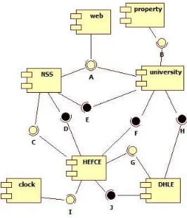
univer-Figure 2: Context Diagram
sity (including university owned and private accommodation costs), employability data from the DHLE agency.
The NSS data is completed by students via a web portal. The details of the information go to the NSS agency and the university is informed of the completion for their records. Private property prices within the geographic area around the university are captured by monitoring RSS feeds from property companies.
Business requirement of KIS, HEFCE, UK etc. overview of requirement. <<STUFF HERE: SAMIA?>>
4.
Applying LEAP
This section takes the reader through the key steps of the method. We provide illustrations of the use of the LEAP method from models constructed from the case study.
4.1 Step 1: Model Requirements 4.1.1 Contextual Analysis
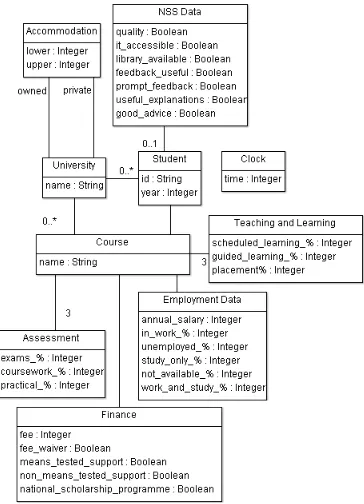
[image:4.612.363.496.266.421.2]Figure 3: Information Model
A student uses a web-portal (web) to complete the NSS survey on-line. When this occurs an event is raised (A); the NSS govern-ment agency handles the event by recording the NSS data; the uni-versity simply records that a student has completed the survey.
A university must maintain information about the prices of private property in the local area. This is achieved via an RSS feed (property) that regularly generates an event (B) that is recorded by the university.
In order to participate in KIS, each university must register with both the NSS and DHLE agencies. Therefore, both agencies pro-vide operations (E and H) for registration that cause a registration event to be raised (G and C). The registration events are processed by HEFCEin any order; both must be received before the KIS cen-sus date.
The KIS census date causes a timing event (I) that is processed by HEFCE causing it to request data necessary to build a KIS re-port. The NSS, University and DHLE components provide suitable operations (D, F and J) for requesting data.
4.1.2 Information Model
Figure 3 shows the information model for the logical architecture. Each University has a number of students with unique identifiers and in a particular year of study. Information is maintained on the cost of both University owned accommodation and private accom-modation in the area. A student studies a course and optionally completes an NSS return in their third year of study; the NSS form allows students to comment on the quality of the University’s pro-vision of teaching and learning in terms of questions such as: ‘Do you agree that you receive prompt feedback on formative assess-ments?’. Each course is delivered in terms of scheduled, guided and practical teaching and learning components, and assessed in terms of exams, courseworks and practicals. Information is maintained nationally about employment statistics for particular courses, such as the salary of graduates and the percentage who are in work or unemployed 6 months after graduation. Each HE course in the UK has a cost and may involve various forms of financial support.
4.1.3 Component Specification
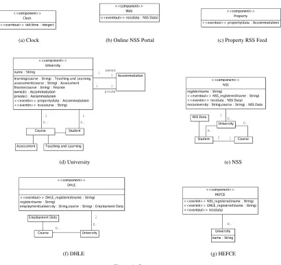
The LEAP simulation language uses components, records, oper-ations and events to model an EA. Figure 4 uses these concepts to elaborate the components from the context diagram in figure 2 using the information concepts from figure 3. Each diagram shows an individual component (identified using the stereotype
<<component>>), its associated data model, the events it expects (<<eventin>>), the events it produces (<<eventsout>>) and the operations that it supports.
Note that several information concepts occur in more than one component. In all cases, information is private to a component, and a system invariant is required if the information is to be consistent. For the purposes of our case study, full information on courses and students is maintained by the university and all other references to these concepts are the unique identifier.
4.2 Step 2: Define L-EA 4.2.1 Simulation Language
A key feature of approach is to simulate both a logical and a phys-ical architecture in terms of components, operations and events. To achieve this we have implemented a simulation language as a Java interpreter. A simulation model consists of a collection of compo-nent definitions of the following form:
componentname (montored components) {
state { ...terms... }
invariants { ...conditions... }
operations { ...function definitions... }
rules { ...rule definitions... } ...nested definitions... }
Each component monitors the events raised by a list of named components. A component maintains a private state that is a list of terms (named records). The component defines an initial state and may add and delete terms. The invariant conditions are boolean ex-pressions over the component’s state; a message is displayed when an invariant becomes false. The operations of a component imple-ment the business processes that form the component’s interfaces; components invoke each other’s operations by sending messages. A component monitors its state and the events it receives from compo-nents it monitors, using rules. Each rule has a collection of patterns that match the terms and events in the component’s state. When all patterns are matched then the rule is ready to fire. The body of a rule is an action that can involve modifying the state or sending messages.
To save space in the rest of the paper we will not give the com-plete definition of each component. Instead, we will provide those elements of thestate,invariants,operationsandrules sec-tions that are essential to understanding how the simulation works.
4.2.2 Context L-EA
The following components define part of the logical EA that pro-vides the context for simulating the university component.
Clock The initial state of a clock is the termTime(0). The clock provides a single operation that is used to drive the simulation. The operation provides an example of anewcommand that adds a new term to the state of the component:
tick() { newTick() }
A clock has a single rule that fires when the clock ticks. It incre-ments the time and raises an eventTime(n), note the use ofdelete
andraiseto remove a term from the state of a component and to raise an event:
tick: t1=Tick() t2=Time(n) {
(a) Clock (b) Online NSS Portal (c) Property RSS Feed
(d) University (e) NSS
[image:6.612.99.509.90.476.2](f) DHLE (g) HEFCE
Figure 4: Components
raise Time(n);
new Time(n+1) }
NSS Web Portal A student uses the NSS web portal to complete the NSS survey. For simulation purposes the initial state of the web component contains terms defining the times at which students complete the survey, and the answers to the questions:
NSS(1,’s01’,’p01’,true,true,true,true,true,true,false) ...
The web component monitors the clock events and has a single rule that raises two events when a student completes a survey. The first event is processed by the NSS agency and the second is processed by the university:
step: Time(t)
NSS(t,id,cid,qual,it,lib,help,prompt,expl,advice) {
raise NSS(id,cid,qual,it,lib,help,prompt,expl,advice);
raise NSS_complete(id) }
Property RSS Feed The property component simulates an RSS feed that supplies bounds on annual rental costs. The initial state is
a collection of terms describing the times at which the data becomes available:
Property_Feed(5,6500,9750) ...
The property component monitors clock events and raises an event when the appropriate time is reached using the following rule:
tick: Time(n) Property_Feed(n,low,high) {
raise Property(low,high) }
Employment Data The DHLE agency is responsible for main-taining employment data on universities and courses. For the pur-poses of the simulation all employment data is part of the initial state:
Employment(’UME’,’p01’,21000,94,2,1,1,2) ...
The DHLE component implements an operation that allows a uni-versity to register. It raises an event when this occurs:
register(university) {
raise DHLE_Registered(university) }
HEFCE will request employment data when it constructs a KIS report. The operation provides an example of thefindconstruct that is used to select an element from a list (in this case the state of DHLE) that matches a pattern; the body of thefindexpression returns a new term:
employment(uni,course) {
find Employment(uni,course,s,w,u,so,na,was) instate { Employment(s,w,u,so,na,was)
} }
National Student Survey The NSS component provides an oper-ation for registering a university:
register(university) {
new University(university);
raise NSS_Registered(university) }
The HEFCE component uses the following operations to re-quest KIS data from the NSS component. In each case a
list-comprehension is used, for example[id | NSS(id,course,true,_,_,_,_,_,_) <- state] processes each element of statein turn, matches it
against the patternNSS(id,...)and returns theidof each element that matches:
quality_score(course) {
length([id | NSS(id,course,true,_,_,_,_,_,_) <-state]) }
it_score(course) {
length([id | NSS(id,course,_,true,_,_,_,_,_) <-state]) }
The following NSS rule is used to handle the event raised by the NSS web portal:
nss : NSS(id,course,qual,it,lib,help,prompt,expl,advice) {
new NSS(id,course,qual,it,lib,help,prompt,expl,advice) }
4.2.3 HEFCE
HEFCE has a census date:
KIS_census(10)
In order for a university to be registered with HEFCE, it must have registered with both the NSS and DHLE components in any order as defined by this rule:
university: NSS_Registered(name) DHLE_Registered(name) {
new University(name) }
When the census date is reached the HEFCE component will make calls on NSS, University and DHLE components to get the KIS data:
kis: Time(t) KIS_census(t) { get_kis_data()
}
4.2.4 University L_EA
The component definitions above provide the context for the logical definition of a university given in this section. The initial state of a university is shown below. It defines several distinct types of infor-mation: the times at which the university registers with the govern-ment agencies; the financial, teaching and learning, and assessgovern-ment patterns for each course; the cost of university owned accommoda-tion; the cost of private accommodaaccommoda-tion; student records that assign a unique id to each student, assign them to a course, define their year of study and record whether or not they have completed the NSS survey:
Register(nss,2) // Register with NSS at time 2.
Register(dhle,3) // Register with DHLE at time 3.
Course(’p01’,8500,true,false,true,false)
Learning(’p01’,[60,30,35],[20,20,50],[20,50,15]) Assessment(’p01’,[70,50,50],[10,20,30],[20,30,20]) ... Lower_Accommodation(7000) Upper_Accommodation(9600) Lower_Private(0) Upper_Private(0)
Student(’s01’,’p01’,3,false) Student(’s02’,’p01’,3,false) ...
NSS_census(5)
A university includes a number of invariant conditions that must be met at all times. The following is an example calledassessments
that requires the split between %-age values for examinations, courseworks and practicals in any given year to add up to 100% for each course. The condition uses theforallexpression that matches a pattern against all elements in a list; the body of theforallmust returntruefor each element in the list that matches the pattern (transis defined in the operations section below):
assessments {
forall Assessment(course,exams,coursewks,pracs) instate{ forall [e_pc,c_pc,p_pc] in trans([exams,coursewks,pracs]) {
(e_pc + c_pc + p_pc) = 100 }
}
} else ’all assessments must add up to 100 in each year.’
A second invariant encodes a business requirement that 50% of all students registered for a course must complete the NSS survey in year 3:
nss_50_per_course {
forall Course(id,_,_,_,_,_) instate{ find UniTime(t) instate {
find NSS_census(t) instate{
let nss = length([id | Student(_,id,3,true) <- state]); students = length([id | Student(_,id,3,_) <- state]) in if students = 0 then true else ((nss/students)*100) > 50 } else true
} else true
}
} else ’ 50% of all students must complete the NSS.’
Atranspositionof a list of lists [[a,b,c],[g,h,i],[x,y,z]]is
[[a,g,x],[b,h,y],[c,i,z]]and is defined using a recursive func-tion as follows:
trans(lists) {
if exists l in lists { l = [] } then []
else [ head(l) | l <- lists ] : slice([ tail(l) | l <- lists ]) }
The following operations are used by HEFCE to access the data necessary in a university to produce the KIS report:
learning(course) {
case find Learning(course,_,_,_) instate {
Learning(n,sched,guided,plmnt) -> Learning(sched,guided,plmnt) }
}
assessment(course) {
case find Assessment(course,_,_,_) instate {
Assessment(n,exams,cw,pract) -> Assessment(exams,cw,pract) }
}
finance(course) {
case find Course(name,_,_,_,_,_) instate {
Course(n,f,fw,mt,nmt,sch) -> Finance(f,fw,mt,nmt,sch) }
Figure 5: Simulation Part 1 (of 3)
A university has the following rules: registerthat registers with the appropriate government agencies when the appropriate time event occurs;clockthat is used to keep a local record of time;
propertythat is used to update the prices of private accommoda-tion using events from the RSS feed;nssthat is used to record the completion of an NSS survey by a particular student:
register: Register(target,time) Time(time) { send(target,’register’,[self.name()]) }
clock: Time(time) {
delete UniTime(time-1);
new UniTime(time) }
property: p=Property(low,high)
l=Lower_Private(x) u=Upper_Private(y) {
delete p,l,u;
new Lower_Private(low),Upper_Private(high) }
nss: NSS_completed(id) s=Student(id,course,3,false) {
delete s;
new Student(id,course,3,true) }
4.2.5 Simulation
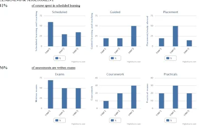
Our approach uses simulation to show that a physical architecture is consistent with the behavior required by a logical architecture. The SLEAP language for the KIS context and logical architecture has been defined in previous sections. SLEAP also provides features for generating a GUI that can be deployed on a web server and accessed via a web browser. We do not show the SLEAP code for the KIS GUI, but the output is shown in figures 5 to 7. The control section in 5 is used to step through the simulation by sending
tick()messages to theclock. Thestepbutton shows the current time and the currently selected course; the rest of the GUI show KIS information for the course.
4.3 Step 3: Collate Physical-EA
[image:8.612.55.236.69.287.2]The next step of our method involves reviewing the current phys-ical as-is system architecture. Most organizations have a systems overview which is used as the input to this step. The result is an un-derstanding of the currently capability of the organization in terms of systems, interfaces, information and events.
Figure 6: Simulation Part 2 (of 3)
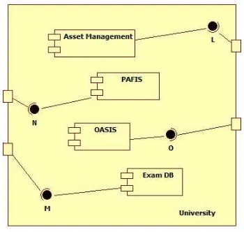
We will use the University of Middlesex (Mdx), London, UK as the basis for our case study. Space limitations prevent us from providing a complete description of the Mdx physical architecture, however it is consistent with most UK HEIs and includes systems for registry, an asset management system that includes a sub-system for university accommodation, an examinations database, a library system, a financial management system called PAFIS, a teaching and learning system called OASIS, an alumni management system, a student portal, and a staff portal.
4.4 Step 4: Configure Physical-EA
Figure 8: Physical Architecture
[image:8.612.349.524.490.656.2]Figure 7: Simulation Part 3 (of 3)
to provide student, accommodation, teaching and learning, assess-ment and financial information. Therefore, for example the P-EA will not include the alumni or library management systems.
The P-EA for Mdx is shown in figure 8 where interfaces have been introduced that support the appropriate delegation of the oper-ations defined by the university component defined in section 4.2.4. The next section defines the components using SLEAP.
4.5 Step 5: Define Physical-EA
The previous section has identified the slice of the Mdx systems that are required to support the KIS case study. This section defines each component using SLEAP.
The asset management system must provide an interface for accommodation pricing:
component asset_management() {
state {
Lower_Accommodation(7000) Upper_Accommodation(9600) }
operations {
lower_accommodation() {
find Lower_Accommodation(cost) in state{ cost } }
... } }
The part of the assessment information that was handled by the university in section 4.2.4 is delegated to the exams database: component exam_db() {
state { Exam(’p01’,[70,50,50]) ... }
operations {
find_exams(name) { find Exam(name,exams) instate } }
}
The Mdx financial management system PAFIS is used to handle information about course costs and support:
componentpafis() {
state { Course(’p01’,8500,true,false,true,false) ... }
operations { finance(course) {
case find Course(course,_,_,_,_,_) instate {
Course(n,f,fw,mt,nmt,sch) -> Finance(f,fw,mt,nmt,sch) }
} } }
The Mdx teaching and learning system OASIS is used to handle the teaching and assessment patterns:
componentoasis() {
state {
Learning(’p01’,[60,30,35],[20,20,50],[20,50,15]) ...
Assessment(’p01’,[10,20,30],[20,30,20]) ...
}
operations {
find_learning(name) { find Learning(name,_,_,_) instate} find_assessment(name) { find Assessment(name,_,_) instate} }
}
The definition of University is then modified to include the compo-nents defined above as sub-definitions. The resulting component is the physical architecture description of University and must include some new invariants. Firstly, information about courses is now dis-tributed amongst a number of systems. We must ensure that the information is consistent, therefore we introduce a new university invariantconformance(seteql4is a predicate that holds between four lists when they all have the same elements):
conformance { seteql4(
[id | Course(id,_,_,_,_,_) <- pafis]) } else ’inconsistent course information.’
Finally, information about assessment for a given course must add up to 100% in any year. The information is distributed between the OASIS and exams systems:
assessments {
forall Assessment(course,coursewks,pracs) in oasis { forall Exam(course,exams) in exam_db {
forall [e_pc,c_pc,p_pc] in slice([exams,coursewks,pracs]) { (e_pc + c_pc + p_pc) = 100
} } }
} else ’all assessments must add up to 100 in each year.’
4.6 Step 6: Conformance
Our EA design method produces a context and both a logical and a physical architecture description using the LEAP language. The logical architecture describes what is required and the physical to-be architecture defines how existing systems can to-be used to satisfy the requirements. It remains to validate the physical architecture by showing that the behavior conforms to the requirements.
In general, conformance can be established using a number of approaches. The context defines a collection of system executions in terms of messages, events and state changes. It is possible to use inspection-based techniques to show that all required executions are handled appropriately by the physical architecture.
More precise approaches are possible. For example, we can define mappings from the physical architecture components to the logical architecture. In the case of the Mdx architecture, the
asset_management, exam_db, pafis and oasis components are merged to become a single top-leveluniversitycomponent. Pro-viding that all operations, events and invariants are consistent then the physical architecture is conformant.
Another approach is to rely on simulation. SLEAP can be used to run the simulation to produce GUI output as defined in figures 5 to 7. If the simulation produces the same output when it is run with both the logical and physical definitions foruniversityon a sufficiently large representative sample of data sets then we have confidence that the physical conforms to the logical. When we run the simulation with both definitions of university given in this paper, the output is the same.
Finally, if we require total confidence in conformance then we need to resort to formal methods such as model checking and theory proving. For large systems such as those found in EA, formal methods are often impractical in terms of complexity. That said, a formal semantics for SLEAP is an area fro future development in order to investigate whether formal methods could help.
5.
Conclusion
Enterprise Architecture remains a confusing and constantly evolv-ing collection of methods and frameworks which are generally characterized by an expansive outlook, lack of precision, a focus on diagrams and an emphasis on document management. The re-sult is that existing approaches are difficult to use. This paper has presented an effort to reduce the scope of EA in order to pin down the core use cases of managing change and better understanding the impact of changing requirements on existing technical architectures of an organization. We have proposed a light weight EA method and its accompanying language that supports precise description of “To be” and “As is” EA. The language by virtue of its design can be used with a simple java based simulation environment to exper-iment with conformance of proposed EA changes. We recognise that there are several limitations with our current proposal but we have demonstrated using a detailed case study that there is merit
and considerable potential in using such an approach understand-ing and managunderstand-ing EA.
References
[1] M. Assmann and G. Engels. Transition to service-oriented enterprise architecture.Software Architecture, pages 346–349, 2008.
[2] T. Bucher, R. Fischer, S. Kurpjuweit, and R. Winter. Analysis and application scenarios of enterprise architecture: An exploratory study. In10th IEEE International Enterprise Distributed Object Computing Conference Workshops, 2006. EDOCW’06, 2006.
[3] R.J.A. Buhr and R.S.O. Casselman.Use case maps for object-oriented systems, volume 302. Prentice Hall, 1996.
[4] J. Cheesman and J. Daniels. UML components. Addison-Wesley, 2001.
[5] T. Clark, B.S. Barn, and S. Oussena. Leap: a precise lightweight framework for enterprise architecture. InProceedings of the 4th India Software Engineering Conference, pages 85–94. ACM, 2011. [6] Desmond F. D’Souza and Alan Cameron Wills.Objects, components,
and frameworks with UML: the catalysis approach. Addison-Wesley Longman Publishing Co., Inc., Boston, MA, USA, 1999.
[7] M. Ekstedt, P. Johnson, A. Lindstrom, M. Gammelgard, E. Johansson, L. Plazaola, E. Silva, and J. Lilieskold. Consistent enterprise soft-ware system architecture for the cio - a utility-cost based approach. In
System Sciences, 2004. Proceedings of the 37th Annual Hawaii Inter-national Conference on System Sciences (HICSS’04), 2004. [8] The Open Group. Archimate technical standard, 2008.
http://www.opengroup.org/archimate/.
[9] J.C. Henderson and N. Venkatraman. Strategic alignment: Leveraging information technology for transforming organizations. IBM systems Journal, 32(1), 1993.
[10] Marc Lankhorst. Introduction to enterprise architecture. InEnterprise Architecture at Work, The Enterprise Engineering Series. Springer Berlin Heidelberg, 2009.
[11] B.M. Michelson. Event-driven architecture overview.Patricia Seybold Group, 2006.
[12] K.D. Niemann. From enterprise architecture to IT governance: ele-ments of effective IT management. Vieweg+ Teubner Verlag, 2006. [13] M.A. Ould. Business Process Management: a rigorous approach.
British Informatics Society Ltd, 2005.
[14] S. Overbeek, B. Klievink, and M. Janssen. A flexible, event-driven, service-oriented architecture for orchestrating service delivery.IEEE Intelligent Systems, 24(5):31–41, 2009.
[15] C. Riege and S. Aier. A Contingency Approach to Enterprise Archi-tecture Method Engineering. InService-Oriented Computing–ICSOC 2008 Workshops. Springer, 2009.
[16] G. Sharon and O. Etzion. Event-processing network model and imple-mentation.IBM Systems Journal, 47(2):321–334, 2008.
[17] J. Spencer et al.TOGAF Enterprise Edition Version 8.1. 2004. [18] R. Wirfs-Brock, B. Wilkerson, and L. Wiener. Designing
object-oriented software, volume 13. Prentice Hall Englewood Cliffs, New Jersey, 1990.
[19] DE Wisnosky and J. Vogel. DoDAF Wizdom: A Practical Guide to Planning, Managing and Executing Projects to Build Enterprise Ar-chitectures Using the Department of Defense Architecture Framework (DoDAF), 2004.
[20] J.A. Zachman. A framework for information systems architecture.