Design of an Intelligent Wireless Communication Module
Based on ARM
https://doi.org/10.3991/ijoe.v14i08.9177
Shihe Wang, Haifei Zhou
Changzhou College of Information Technology, Jiangsu, China
Abstract—To transmit information quickly and accurately and improve work efficiency, reduced instruction set computer (RISC) processors and tech-nologies related to advanced RISC machines (ARM) were applied. The design of an intelligent wireless communication module based on ARM was completed using the wireless communication module for wireless communication, wireless control, wireless meter reading, industrial data acquisition, and other applica-tions. Results showed that the designed smart wireless communication module had certain feasibility. In life communication, the transmission and reception of information were completed quickly and intelligently. This feature expanded the geographical scope of application and enhanced the expansion. Therefore, the smart wireless communication module has the advantages of accuracy, high efficiency, and humanization. Its utilization can bring convenience in people’s lives and communication.
Keywords—ARM, intelligence, wireless communication module
1
Introduction
Wired data communication often encounters various problems, such as difficulty in wiring the site environment, cumbersome mining of cable trenches, and inability to connect and expand new modules. Communications also fail due to the influence of mountains and lakes. The advent of the post-PC era has enabled the development of embedded advanced reduced instruction set computer machine (ARM) technology. People are increasingly demanding instant messaging. Accuracy and efficiency are the goals of modern communications. The wireless communication module is an effective choice among many solutions. This module is mainly composed of a trans-mitter, a receiver, and a controller. At present, the module has been applied to many fields, such as industrial transmission, transportation, and military medical treatment. The design of intelligent wireless communication modules based on ARM has be-come an inevitable trend of development.
entered people’s lives. Later, communications and computers were combined. The development of wireless communication technology based on ARM has been acceler-ated, and smart wireless communications have become a comprehensive technology. The 21st century is a critical period for the development of smart wireless communi-cation modules. At present, wireless communicommuni-cation modules are widely used in vari-ous fields. This utilization eases people’s lives. The wireless communication module has adapted to the development of society and the needs of people’s lives. However, China’s current wireless communication module level is still in a relatively rigid phase in practice. A relatively large space for development and use is available. Therefore, additional intelligent wireless communication modules can be designed using ARM.
2
State of the art
The single-line high-speed digital subscriber line technology is a point-to-point high-speed data transmission technology. Li et al. [1] used this technique for long-distance local area network connections to meet the user’s long-long-distance requirement, small-capacity enterprise network leased line interconnection, and symmetrical band-width Internet access. The VxWorks-based wired communication module uses the ARM9 control chip as the master chip to complete the configuration and control of the communication chip SDFE-24624. This module also provides the function of state information reporting, host control, and automatic reconnection. Modules can auto-matically run connections without human intervention. The use of the entire module is convenient. Abbasi et al. [2] studied the design of a smart 1553B bus communication module based on an ARM processor. With the embedded CPU, the 1553B bus data can be packaged and reassembled within the module, thereby realizing the one-time transmission of multiple sets of data and the consumption of computer system re-sources at the bottom. According to actual tests, the efficiency of this method is great-ly improved compared with the traditional 1553B bus module. The design method of intelligent processing within the module is confirmed. It can also be extended to the design of other intelligent low-speed bus communication modules to improve the performance of the entire system.
through WiFi. The final wireless communication module can send smart car data to the host computer. The intelligent vehicle data received by the upper computer is displayed and stored, and the speed is up to 11 kB/s. This design facilitates the de-bugging of the smart car control system. The operating status of the smart car micro-controller program is accurately controlled, which provides a scientific basis for the improvement of the algorithm. The smart car wireless communication adopts the mutual cooperation of Bluetooth technology, nRF24L01 wireless module, and zigbee, and it reaches the Wi Fi-based smart car data wireless communication module design.
In the later part of the 20th century, the development of large-scale integrated cir-cuits has increased the integration of the design with electronic components and has made its functions powerful. Coupled with the universal application of 8-bit micro-processors, the industrial automation instrumentation industry has undergone qualita-tive changes. Suryadevara et al. [5] pointed out that the combined microprocessor technology of the centralized computer control system has developed the overall de-centralized control system of the microprocessor, namely, the microcomputer distrib-uted system. On this basis, Carlsson et al. first published the TDC2000 overall decen-tralized control system. The system can complete eight loop controls separately, and the basic controllers of each loop can be set independently. The communication sys-tem is served by the data highway’s bus as a network medium. Several basic control-lers and cathode ray tube operation stations are connected to ensure that each node has computer decentralized control and centralized display management at the opera-tion staopera-tion. At the same time, the United States, Japan, Britain, France, and Germany have also started to develop corresponding products. At that time, the system was mainly used in analog control loop-based systems, including chemical engineering, electricity, petroleum, metallurgy, and other public projects; such products are collec-tively referred to as distributed control systems (DCS).
The main manufacturers of DCS control systems (e.g., Honeywell’s TDC300O\MICRO, TDC3000X, Foxboro’s I/A Series, and Westinghouse’s WDPF, Yokogawa’s CENTUM CS, Germany’s Siemens’ TELEPERM and SIPAOS 200, and ABB’s MOD300) are concentrated in the United States, Germany, Japan, and other countries. The fieldbus control system (FCS) is a fifth-generation process control system. It became practical in the 1990s and is rapidly developing with a rapid mo-mentum. Foreign companies have been focusing on the promotion of FCS and FCS meters in recent years and have invested less in wireless communications on the sys-tem. A few manufacturers have wireless communication cards, but these cards are costly.
many DCS manufacturers in China integrate production and research and develop-ment, such as Ho Li Shi, Zhejiang central control, and Shanghai Xinhua. In China’s petrochemical industry, thousands of large and medium-sized DCS systems are in use. The application level can reach 90% of the automatic operation rate. Domestic manu-facturers have occupied a certain scale of the domestic market by their superior cost performance. The products are even exported to foreign countries. Qin argued that the role of the DCS control system in industrial control is irreplaceable. Although fieldbus technology has gradually emerged, the company has introduced its own bus technology because no unified standard exists to date. Openness and interoperability are difficult to unify. In addition, the cost is high, and the technology is insufficiently mature to win a wide market. In the future and even in a long period of time, the sta-tus of DCS in petrochemical and other special industrial controls is unclear. Tasks such as the improvement in functions after the replacement, the transparency of new technology compatibility, the improvement in application service level, and the reduc-tion in the product market price are also urgent issues.
Anisi et al. [7] used the flexibility, security, and reliability of ARM to strengthen rescue efforts. The designed system uses an ARM11 processor as a controller. WiFi wireless ad hoc network is used for rescue communication. The system uses modular programming and integrates many rescue techniques. Some hardware circuits have been modified to improve functionality. The experimental results showed that the system is full featured, efficient, and practical. This method can be applied to the complex environment of a major accident site and has a high engineering practical value. Gunduz et al. [8] studied the application of Bluetooth technology with embed-ded ARM technology in industrial data communication. They also developed a set of wireless data communication modules based on ARM. The system includes three parts: embedded system based on ARM Bluetooth module, Bluetooth communication link, and Bluetooth adapter. The system has the characteristics of small size, powerful function, convenient operation, and friendly man–machine relationship.
In summary, compared with the previous hardware and software platforms, the hardware integration of the system is greatly improved. The cost is significantly re-duced, the development cycle is shortened, and the error rate is decreased. The ARM processor has three major features: low power, 16-bit/32-bit dual instruction set, and numerous partners. This technology is applied to smart wireless communication mod-ules, which is favored by increasing number of companies and people. Therefore, the design of smart wireless communication module based on ARM is important. In this study, smart wireless communication modules based on ARM technology are de-signed. ARM and wireless communication technology are further developed and applied.
3
Hardware design
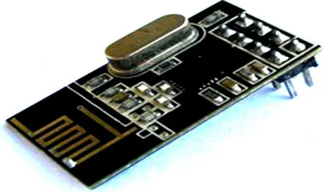
an H-Jtag debugging excuse; and a switch to select the start mode. It is a basic condi-tion for the operacondi-tion of an ARM embedded system. In addicondi-tion, the module has some peripheral circuits and four USB ports. A USB interface acts as a slave interface for downloading the kernel and file system from the host under the boot loader. Three other USB ports serve as master interfaces for connecting USB external devices. Three TEL level 9-hole serial ports are connected with a wireless data transmission module and a GPS module after level conversion. A TEL is used to communicate with the host during debugging. An Ethernet interface is used to mount the file system through the network file system (NFS) protocol from the host during the debugging phase and to download the kernel and file system from the host using the trivial file transfer protocol (TFTP) or NFS protocol during the development phase. An image acquisition module is used to capture real-time images. A touch-screen liquid crystal display is used to display the acquired images and user interface. A video graphic array port can be used to access the PC display screen, an audio interface is used for sound collection, and a buzzer is used to debug the sound. Figure 1 shows the overall framework of the wireless communication module, and Figure 2 shows the physical object. GPRS Module Wireless data transmissio n module PC debugging Serial port SDRAM(64MB) ARM main controller NandFlash(512MB) Narf Jash(2 MB) Reset switch Active Crystal Debug module Power module audio port switch
USB slave interface
VGA adapter board
USB host device interface RTC battery
Ethernet interface Image acquisition
module keyboard
LCD with touch screen
buzzer GPRS
Module
Fig. 2. Physical object
4
Boot loader transplantation
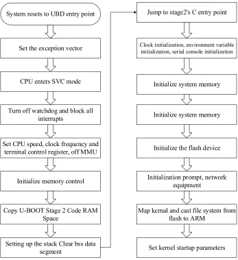
System resets to UBD entry point
Set the exception vector
CPU enters SVC mode
Turn off watchdog and block all interrupts
Set CPU speed, clock frequency and terminal control register, off MMU
Initialize memory control
Copy U-BOOT Stage 2 Code RAM Space
Jump to stage2's C entry point
Clock initialization, environment variable initialization, serial console initialization
Initialize system memory
Initialize system memory
Initialize the flash device
Initialization prompt, network equipment
Map kernal and cast file system from flash to ARM
Setting up the stack Clear bss data
segment Set kernel startup parameters
Fig. 3. U-boot startup flowchart
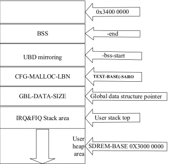
BSS
GBL-DATA-SIZE
UBD mirroring
CFG-MALLOC-LBN
IRQ&FIQ Stack area
User
heap
area
Fig. 4. Mapping of SDRAM storage space for the entire system
4.1 Linux kernel transplantation and root file system production
The Linux2.6 operating system supports nearly all embedded processors on the market and has good portability. However, the Linux kernel downloaded from the official website cannot be run on a fixed hardware platform. Corresponding changes to the hardware-related parts of the Linux kernel must be made on the basis of the CPU architecture and board design. Then, a cross-compiled environment that has been built is used to compile the new Linux kernel and then download it to the board to run.
4.2 Embedded Linux
Device-driven porting and development are completed, and the hardware platform can run. Various peripherals cannot be used because of their lack of a driver support. The next step is to install drivers for each external device. The underlying hardware details are masked. This way provides the upper-level application with all the inter-face functions for operating the underlying hardware devices, thereby allowing appli-cations originally developed on a general-purpose PC to be ported to the platform without substantial modifications. The development process of the communication module involves only three major device drivers for embedded Linux, but the plat-form virtual bus mechanism is introduced from Linux2.6. The three completely dif-ferent types of device drivers can all be managed and registered using the platform. Compared with the traditional device-driven development mechanism, the platform mechanism has a distinct advantage in that the device and driver are managed sepa-rately, and the independence of the driver and resources is improved. As a result, the portability and security of the device driver are enhanced. The platform mechanism is simple and consists of two parts, namely, platform device and platform driver.
5
System design
The main modules of the system software include an initialization module, a data sending module, a data receiving module, and a data processing module. The initiali-zation module is responsible for the system initialiinitiali-zation operation. The data sending and receiving modules are responsible for the correct sending and receiving of data, respectively. The data processing module is responsible for the data processing.
5.1 Software design
control. Here, the settings of the serial communication baud rate in the Linux system are briefly introduced.
To control the serial port, the termio structure is applied. The port baud rate is ob-tained through the cfgetispeed and cfgetospeed functions. The cfgetispeed function is used to obtain the input baud rate information in the structure termios_p. The cfge-tospeed function is used to obtain the output information in the structure termios_p.
The data sending and receiving modules send and receive the data to be sent in the form of a file. Before reading and writing to a file, the file is opened with the function open(const char*pathname,int flags). After reading and writing, the close(const char*pathname,int flag) function is used to close the file. The problem that needs attention is handling overflow when reading and writing files. The tcflush() function is used to handle overflow problems. When sending and receiving data, the file is sent in blocks to guarantee the correctness of data transmission and reception.
5.2 Process of software design
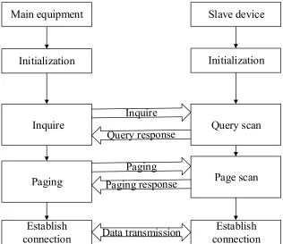
The communication module establishes the communication connection with the slave device through the host control interface. This process is the key to establishing wireless communication. Figure 5 shows the process of establishing a wireless com-munication connection.
Main equipment
Initialization
Inquire
Paging
Establish
connection
Slave device
Initialization
Query scan
Page scan
Establish
connection
Data transmission
After the communication master and slave devices complete their initialization, the master device is in the inquiry state. The device is in an inquiry scan state. The master device determines whether a slave device is in the inquiry scan state by querying. The master device is in the paging state, and the slave device is in the page scan state. A master device sends a paging request. When the device chooses to accept the request, the connection is established. If the request is rejected, then the connection fails. If the master device knows the device address of the slave device, then the inquiry process may be omitted.
The adapter can send and receive data, and multiple nodes can form a piconet. In a piconet, a master can control up to seven slaves. Therefore, seven transceivers can send and receive data at the same time. The wireless communication module sends data, and the USB adapter transmits the received data to the PC through the virtual serial port. The virtual serial port has the same transmission principle as the serial port. Using vc++, the serial transmission receiver program is written. The USB Blue-tooth adapter sends data through the virtual serial port. The application uses vc++ to write a serial send program. After the Bluetooth module receives the data, it sends the data to the processing section for processing.
6
System debugging
The first phase completes the design of the module. The basic process and configu-ration of the module work are summarized. The second phase of the debugging task is based on the ARM-based smart module embedded system design and debugging program and interface control design. ARM-based smart embedded systems are test-ed.
The communication debugging process of this system is as follows:
First, the communication module is connected to the serial port of the ARM em-bedded system.
Second, the configuration commands of the module are used to complete the con-figuration of the communication module. The communication module is set as a slave communication module, a slave device that sends, transmits, and receives data, and a slave module as a communication module.
Third, the intelligent interface for sending messages is opened, and the automatic query module is started. After finding the module, the automatic communication con-nection is completed.
Fourth, in the interface connection, the device of the embedded system Bt-device-01 of the intelligent wireless communication module based on ARM is found. The embedded system and communication equipment are successfully connected. Data can be transmitted in the form of voice, text, pictures, and video for communication.
Fifth, the communication program code is run to send and receive files.
After repeated testing, the module can be used for wireless transmission to achieve data communication.
communication protocols are tested. The process is divided into a non-identifier pack-et protocol and an identifier packpack-et protocol. An identifier data packpack-et refers to a data packet that contains a header, a sequence number, valid data, a check code, and a trailer. This packet is convenient for distinguishing valid data, from packet data transmitted by the lower device. The non-identifier data packet contains only standard source signal data. Protocol testing includes indoor testing (5 m distance) and outdoor testing (100–150 m distance). The installation height is 3 m, the antenna is vertically upward, and the environment between the wireless modules is visible. The lower computer sends data to the upper computer for a period of 70 s, and each week sends data to 30 groups. The test time is set to 700 s, and the number of sent data is 300 groups.
7
Conclusions
In this study, wireless communication technology is combined with embedded ARM technology and data communication. A set of ARM-based smart wireless communication modules is developed. The system includes three parts: embedded system based on ARM intelligent module, communication link, and adapter. The hardware system platform is compact and powerful. The Linux operating system is smart and simple. The development of communication application software is feasi-ble. The software can achieve the expected wireless communications.
Wireless communications, as an emerging industry, have brought benefits econom-ically and practeconom-ically over wired communications. ARM technology has strong practi-cality and is low cost. Wireless communication has the advantages of wide coverage and high real-time. Information is fast and accurate in the process of transmission, which greatly facilitates people’s lives. With the continuous maturity of ARM tech-nology and its increasingly prominent advantages, the application of ARM in wireless communications is expected to increase.
8
References
[1]Li, J. Q., He, S. Q., Ming, Z., & Cai, S. An intelligent wireless sensor networks system with multiple servers’ communication. International Journal of Distributed Sensor Net-works, 2015, vol. 11(8), pp. 960173. https://doi.org/10.1155/2015/960173
[2]Abbasi, A. Z., Islam, N., & Shaikh, Z. A. A review of wireless sensors and networks' ap-plications in agriculture. Computer Standards & Interfaces, 2014, vol. 36(2), pp. 263-270.
https://doi.org/10.1016/j.csi.2011.03.004
[3]Sundar, R., Hebbar, S., & Golla, V. Implementing intelligent traffic control system for congestion control, ambulance clearance, and stolen vehicle detection. IEEE Sensors Jour-nal, 2015, vol. 15(2), pp. 1109-1113. https://doi.org/10.1109/JSEN.2014.2360288
[4]Huh, J. H., Otgonchimeg, S., & Seo, K. Advanced metering infrastructure design and test bed experiment using intelligent agents: focusing on the PLC network base technology for Smart Grid system. The Journal of Supercomputing, 2016, vol. 72(5), pp. 1862-1877.
[5]Suryadevara, N. K., Mukhopadhyay, S. C., Kelly, S. D. T., & Gill, S. P. S. WSN-based smart sensors and actuator for power management in intelligent buildings. IEEE/ASME transactions on mechatronics, 2015, vol. 20(2), pp. 564-571. https://doi.org/10.1109/TM ECH.2014.2301716
[6]Shahzad, G., Yang, H., Ahmad, A. W., & Lee, C. Energy-efficient intelligent street light-ing system uslight-ing traffic-adaptive control. IEEE Sensors Journal, 2016, vol. 16(13), pp. 5397-5405. https://doi.org/10.1109/JSEN.2016.2557345
[7]Anisi, M. H., Abdul-Salaam, G., & Abdullah, A. H. A survey of wireless sensor network approaches and their energy consumption for monitoring farm fields in precision agricul-ture. Precision Agriculture, 2015, vol. 16(2), pp. 216-238. https://doi.org/10.1007/s11119-014-9371-8
[8]Gunduz, D., Stamatiou, K., Michelusi, N., & Zorzi, M. Designing intelligent energy har-vesting communication systems. IEEE Communications Magazine, 2014, vol. 52(1), pp. 210-216. https://doi.org/10.1109/MCOM.2014.6710085
9
Author
Shihe Wang and Haifei Zhou are with Changzhou College of Information
Tech-nology, Jiangsu, China.