INTRODUCTION
Today’s modern agriculture industry requires a wide variety of equipment and special machine systems. Several factors such as the addition of new equipment, wearing of current equipment and fuel consumption significantly increase the costs of land processing operations [3, 4]. For sustainable agriculture, it has become important to reduce the costs of agricultural operations, to preserve soil quality to minimize the use of en-ergy and to reduce the processing time [5].
Although mechanization needs of modern agriculture vary depending on several factors such as costs, climatic factor and stressed soil, there are some permanent mechanisms that are widely used. Disc harrow is one of these. Disc harrow is an efficient method for willow primary tillage in terms of power requirement [17]. A modular roller adaptation is aimed in order to
al-low this traditional agricultural operation equip-ment to perform in a more efficient manner. Utilization of combined and modular systems is an effect solution for sustainable agriculture. Functional and modular product development would be a reasonable attempt to resolve the needs. Computer systems enables this process to become fast and economic.
Disc harrow, which was designed with CA-TIA in the product development stage, was stud-ied with structural stress analyses. Weight and re-sistance relationship is significant in agricultural mechanization systems. An excessively heavy system would require a high bollard pull. Fur-thermore; it is difficult to carry a heavy machine on soil ground. Therefore; the methods used in the designs of computer-aided engineering based chassis, were analyzed. Javadi and Hajiahmad [8] aims of this research was to develop a new com-bined machine for sufficient clod breaking as well
COMPUTER AIDED ADAPTIVE SYSTEM DESIGN WITH ENGINEERING
SYSTEMATICS AND MANUFACTURING
Gurkan Irsel1
1 Department of Mechanical Engineering, Trakya University, Edirne 22100, Turkey e-mail: [email protected]
Research Journal
Volume 11, Issue 4, December 2017, pages 83–96
DOI: 10.12913/22998624/77069 Research Article
ABSTRACT
This research practically discusses and presents the stages of design process in prod-uct development. Design process was realized through CATIA. The prodprod-uct devel-oped is an agricultural device called as “disc harrow”. Therefore, agricultural details are presented together with machine design. A roller system is added to disc harrow in this study. Thus; the current system and the additional roller system are discussed with the principles of methodological construction and design objectives are defined. Both the current system and the additional roller system are designed in parallel with these objectives. Structural stress analysis is performed at different kinetic positions of the disc harrow connection of the roller system. System design is achieved by considering the feedback from such analyses and design objectives. The hereby design is obtained. The additional roller system is mounted and field survey is carried out. Contribution of the roller to disc harrow process, defined design objectives, ratio of the realization of design objectives and results of stress analyses are evaluated.
Keywords: CATIA, structural analysis, shape design, adaptive structure, product de-velopment, disc harrow
as surface uniformity in one pass and the shortest possible time. The machine was combination of a disk harrow and a Cambridge roller. The com -bined machine was field tested in a research sta -tion with loamy soil texture. Treatments of disk harrow once; disk harrow twice and combined machine applied after moldboard plowing. Us-ing combined equipment and reducUs-ing number of passes has gained popularity due to its effect on time, efficiency and costs. Disk harrow is the most common equipment used for clod breaking compared to weed control or residue mixing after moldboard plow. Serrano et al. [22] soil-work -ing operations in conventional farm-ing systems involving the use of the tractor are some of the operations that incur the highest energy costs. Oz-turk and Bastaban [19] combined machines such as spike harrow + disk harrow; disk harrow + packer roller and cultivator + spiked harrow had positive effect on soil loosening, bulk density and surface clod breaking. Rahman et al. [20] stud -ied stress analysis on heavy duty truck chassis by finite element package ABAQUS. They sug -gested improving the fatigue life of components at critical points through design modifications by reducing stress. They suggested that, yield stress at critical points were decreased. Karao-glu and Kuralay [9] did stress analysis of heavy duty truck chassis with riveted joints by using a finite element package ANSYS version 5.3. They examined the effect of the side member thick -ness and connection plate thick-ness with length change. Tiwari and Joshi [25] mounted the gear models with CATIA. CAD data were transferred to ANSYS and stress analyses were performed. Krishan and Aggarwal [11] CAD modeling of the multi leaf spring structures also includes many complicated parts, which are difficult to make by any of other CAD modeling other than Finite El-ement software. CAD modeling of the complete Multi Leaf Spring structure is performed by us-ing CATIAV5 R17 software. Nor et al. [18] de -termine the stress analysis of an actual low loader structure having I-beams design application of 35 ton trailer. They use CATIA V5R18 for model-ing. Agrawal [2] in Static Analysis, we can de-termine highly stressed area of truck chassis. Ko -tari and Gopinath [13] modeled chassis through CATIA and performed ANSYS stress analyses. They turned a system with a load bearing capac-ity of 10.4 tones into a system with a load bearing capacity of 14 tons. Agrawal and Razik [1] used CATIA and ANSYS to perform an optimization study. Truck chassis was designed with CATIA.
ANSYS was used in analyses. Magdziak [16] performed his turbine wing with the assistance of CATIA optimization method. Irsel [7] Computer Aided Engineering Design Optimization process is studied experimentally with CATIA Product Engineering Optimizer module and optimization algorithms within limitations are used. Benefits of the optimization procedure are also evaluated. Optimization process has great importance in the design of machine parts and constructions. One of the primary duties of engineering is to offer a more resistant and a lighter structure and to mini-mize the stress in the system. Besides resistance and weight, there are too many design parameters to be evaluated and considering too many design parameters will bring along too many solutions. Thus, it will be wise to use an optimum design in the analysis to achieve the desired goal [10]. In this research, a compressed seed bed involving tinier particles in a single pass with disc harrow was integrated with a roller in order to obtain a smoother surface.
The basic purpose of this research is to of-fer the design of a roller system mechanism to be adapted to the current disc harrow and to produce and evaluate such design. With respect to that, the design was revealed out through the principles of methodological construction and dimensions were determined through mounting stress analy-ses. Structural stress analyses were performed with CATIA for VI different positions represent -ing a cycle activity. The designed system was then produced. Field surveys were performed. The re-sults were presented through tables and figures.
MATERIAL AND METHOD
Description of the Current System
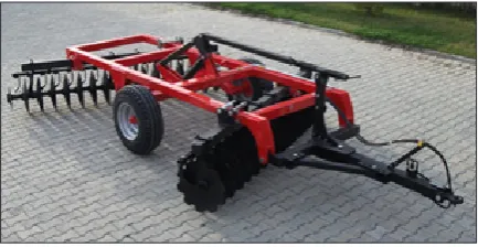
The disc harrow discussed here is the offset type disc harrow with 46 cm disc diameter. Discs are placed in two rows. The row looks has a “V” form when looked from above (Figure 1). Con -cave surfaces of the discs are in opposite direc-tion to each other in the first and second rows. Commonly, there is 17 cm to 24 cm distance be-tween the discs. 46 cm, 51 cm or 56 cm are fre -quently used in agricultural processes in Turkey. The structure obtained after processing with discs with a diameter above 51 cm would be deeper and have fewer particles.
-tor bollard pull depending on the type of soil and wetness [23]. Figure 1 presents light type (disc with 46 cm diameter and 17 cm disc distance) disc harrow. The two carrier wheels available in the middle part of the system contact the ground and pull the system up with the aid of a hydrau-lic cylinder and mechanism. Thus; the contact of discs with the ground is broken. This is a very useful and ergonomic method both during perfor-mance and on the way. Furthermore; the carrier system is related to the pull profile of the trac -tor with an upper bond. This bond is mostly con-nected to the pull profile by a spring. This upper bond is used in the contact of the main chassis of disc harrow with the ground and to preserve the horizontal position on the way.
When authentic offset disc harrow models produced by different manufacturers are exam -ined, the most important difference that comes out is the constructive robustness and weight. Too much constructive weight cause discs to go much deeper into the ground. Disc harrows with 20–36 discs have weight varying from 1350 to 3500 kg. When discs go into the ground deeper than desir-able level; mounting beds contact the ground and wear out, oil seals are stressed, bearings are filled with tiny sand particles and there emerges the need for greater bollard pull. The need for great-er bollard causes excessive fuel consumption, reduction of work capacity and speed and thus, leads to reduction of processing capacity. There-fore; minimum weight and weight that could be added to the system are significant for various ag -ricultural mechanization systems. There are also disc harrows which possess a main chassis that can be filled with water.
Design Objectives
Considering the design factors with respect to the functionality of disc harrow; machine-ground constructive relationship, bollard pull require-ment and cost per cycle are the most important
factors. Methodological construction design ob-jectives were defined in order to achieve a design that would have a positive effect on these impor -tant factors:
• For the functionality of the roller, the breadth of the roller to be added to the system will be 20 cm wider that the current disc harrow breadth. Consequently; the breadth of roller will be 3.5 m.
• The roller to be mounted on the main chassis of disc harrow will be of modular type and it will be suitable for use with different agricul -tural machines.
• Disc harrow-roller carrier for modular sys-tems will be able to carry different equipment, as well. Therefore; carrier connection will be suitable for a standard profile.
• It will be possible to deactivate roller by hy-draulic cylinder when there is no need for its operation. This will be performed from the tractor and be ergonomic.
• Roller will be close to disc harrow’s center of gravity on the way and will be located on the chassis.
• As the diameter of the roller gets larger, roll-ing resistance decreases but weight increases. Taking disc harrow’s disc diameter into con -sideration, it would be suitable for the roller to have a diameter of 500 mm.
• There will not be a shaft passing through the center of roller in order to prevent soil stick on the roller.
• Roller-ground surface contact sheets will not be in a plain form. A conic profile with depth is required for compression.
• Roller contact sheets must have helical order. This is significant for continuous contact of the roller with the ground. Otherwise, roller cannot apply an equal pressure force on the surface.
• Roller will only be bedded from its two sides in order to prevent that there is no breadth left non-contact throughout the processing breadth.
• The roller attached to the back side of the cur -rent system will change the gravity center of the system. Thus; the current system balanc-ing connection will be adjusted by a hydraulic cylinder. This process is not related with roller connection system design.
• The roller will not be of additional weight to the disc harrow. When the roller is in contact with the ground, it will be able to carry its own weight without submerging. Therefore; the
sheets to contact with the ground in a helical way will have 10 mm wall thickness.
• For this system it would be appropriate to take security coefficient as 2 in the work area and as 4 on the way.
• The weight of roller will vary from 60 to 70 kg per meter.
• Roller connection fork will have maximum 200 kg weight.
• It would be sufficient to use one hydraulic cyl -inder for the roller system. The hydraulic cyl-inder selected here possesses 780 mm closed 1260 mm open position and 480 mm stroke. Design will be shaped in parallel with the di-mensions of hydraulic cylinder.
• Maximum stress will necessarily be on mount-ing pins. This is important for eliminatmount-ing the any system damage with minimum cost.
Adaptive Design with CATIA
CATIA’s Part Design, Assembly Design, Gen-erative Structural Analysis and Drafting modules were used in this research. Parts were modeled and mounted, stress analyses were mostly per-formed during mounting. Necessary details for plasma shear and production were transferred to 2D environment in drafting module.
Modeling of the Current Disc Harrow Chasis Main chassis of a common disc harrow has a simple and plain structure, indeed. It consists of a rectangular body made of standard rectangular profiles and of connection elements [8]. The main chassis presented in Figure 2 for roller adaptation design is made of 150 mm x 100 mm x 8 mm standard profiles. Wheel connection plates were also created for analysis. As the whole system is going to be studied through stress analysis, this chassis design is sufficient to protect against the negative impact on computer capacity.
Modeling of the Roller
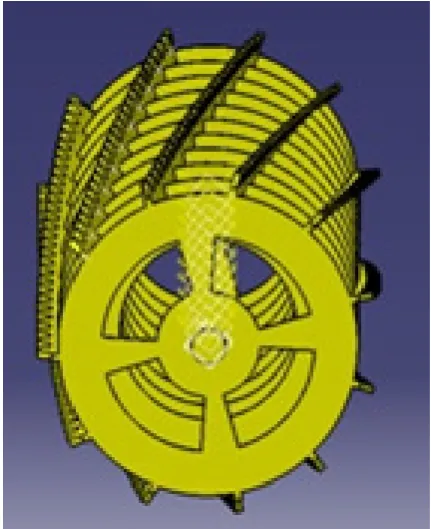
Plate arrangement of a helical positioned roller with 50 cm outer diameter is presented in Figure 3. The conic shaped structure to compress the ground is presented in Figure 4.
Roller contacts the ground at each moment of rolling. Material of the designed roller is St 37 and its weight is 235 kg. Roller design is pre -sented in Figure 5. Shaft is designed for bedding to the flanges on two exterior sides of the roller. These shafts are bedded to the roller. Shaft diam-eter is 50 mm.
Two pieces of SKF brand shaft bed unit are preferred for roller bedding. This unit consists of a bed, bearing and seals. Each unit is mounted us-ing 4 screws and becomes ready for use. Bed life -time for SKF bearings is calculated on the online calculation module [24].
Carrier Fork Design
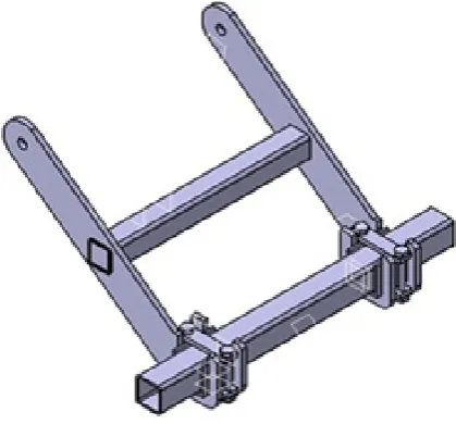
Carrier roller fork was created in parallel with the principles of methodological construction. This fork can be used for the mounting of 100 mm square sectioned profiles. Form fastening and profile were wrapped from the bottom using jaws. While the 100 mm square profile was inside the jaws, mounting was performed from the up-per part using one plate and two screws for each. Left, right and up motion of this connection pro-file was restricted. The box propro-file positioned in
the middle of the two forks made the chassis of the fork carrier. Hydraulic system connection was made on this profile. The two holes seen on the carrier fork in Figure 6 were made for connection to the main chassis of the disc harrow.
With pins, the carrier fork was mounted be -tween twosome plates welded on disc harrow through two upper holes. Pin-connected mount-ing was performed in such a way that one arm of the fork would be the other arm between the other two plates. The distance between two forks was 781 mm at chassis-carrier fork connection. The fork was at bottom position with 115.2° angle
(Figure 7). When the fork was in this position, the roller was positioned according to the chassis of disc harrow. This distance would be suitable to make sure that discs would not spill soil on the roller. SKF 205 bearing units were mounted on the shafts welded on roller side flanges .
At this position of roller, two side plates were formed. Two 20 mm holes were drilled on this plate. These holes are for system mounting hang-er and for the attachment of any additional system on the roller (Figure 8).
Carrier Fork – Hydraulic Cylinder Mechanism Design
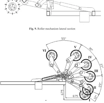
In Figure 9, there is a section belonging to the roller motion mechanism. This section is a gen-eral view at 345 mm stroke of the hydraulic cyl -inder. Shorter arms in 270 mm length determine the roller’s motion depending on the hydraulic cylinder stroke.
The detail regarding the roller motion mechanism design was presented in Figure 10 with the kinematic analysis of the mounting design. Roller’s motion was studied for 6 po -sitions for 480 mm hydraulic cylinder stroke.
Fig. 4 Plate – rich contact conic profile.
Fig. 5. Roller design solid model
Fig. 6. Carrier fork system Fig. 8. Roller bed connection plates design
Roller position was: I for 480 mm maximum stroke of the hydraulic cylinder and it was: VI for 2 mm stroke of the hydraulic cylinder. 478 mm stroke was used in total to have the 2 mm hydraulic cylinder to keep the system at tense level. In this design, the area between position I and positions I-II is the processing area of the roller. In this area, maximum vertical motion aimed and enabled for the minimum progress of the hydraulic cylinder. For 1 mm progress of the hydraulic cylinder, the roller performs 5.30 mm vertical motion in average. Between posi -tions V-VI, the roller performs 7.66 mm hori -zontal motion in average for 1 mm progress of the hydraulic cylinder.
Once connection points and arm lengths were determined, hydraulic cylinder roller motion mechanism solid model was created (Figure 11).
Structural Stress Analysis of Adaptive System The ground-based vertical force on the arm system roller F1 and horizontal force was F3 whereas the force on the hydraulic cylinder was F2. F2 force was created with the directing of the 270 mm-long arms. In structural stress analysis,
Fig. 9. Roller mechanism lateral section
Fig. 10. Roller position depending on the stroke change of the hydraulic cylinder
F1 and F3 forces were defined the compound force as a single force (Figure 12).
Total weight of roller and fork carrier was 433 kg. 4.5 kN distributed load was applied on roller on the way. As the weight of the chassis could also pose a pressure on roller during contact with the ground a 8 kN force was applied. Under the influence of these forces, the system was studied with structural stress analysis during mounting.
The connection between the mounted parts was defined with general analysis connection icon. The analysis had 37 connections (Figure 13). The system consists of 26 parts. Thus; the analysis involves 26 different mesh definitions. General analysis connection definitions are of fastened mesh nature. It is important to create suitable mesh structure in CAD programs us-ing finite elements methods for the performance of structural stress analysis. Linear element was used. Global error rate was 34% for the selected mesh size (Figure 14).
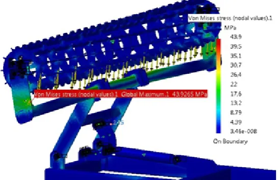
As in Position I, stress analysis was per-formed with 8000 N load, max 111 MPa Von Misses stress result was achieved maximum stress was observed on mounting pin (Figure 15). Maximum collapse value was detected to be 17.4 mm in Position I (Figure 16). Maximum stress value was 53.9 MPa (Figure 17) at Position IV. Maximum collapse value was 8.37 mm at Posi-tion IV (Figure 18). Stress value at PosiPosi-tions II, III and IV was around 50 MPa. Maximum stress value at Position VI was 43.9 MPa (Figure 19). Maximum collapse value was 2.88 mm at Posi-tion VI (Figure 20).
Fig. 12. Roller system section and force effect
Fig. 13. General analysis connection and mesh design
Fig. 14. Global mesh error rate
Fig. 18. Collapse distribution at Position IV
Fig. 16. Collapse distribution at Position I
RESULTS
Roller adaptation system design was made through systematic and planned (methodological) evaluation of several factors such as weight, ma-terial, motion, mounting, transportation, energy, ergonomics, security, drive method, production method etc.
The system was studied at 6 different posi -tions depending on the hydraulic cylinder stroke (seen in Figure 8). Kinematic motion of the roller desirable at X (horizontal) and Y (vertical) angles depending on the stroke of hydraulic cylinder was achieved through the sizing of parts. At Position I and II, the roller performs around 5.30 mm verti-cal motion for 1 mm progress of this hydraulic cylinder between these two positions. For 1 mm progress of hydraulic cylinder between Position V and VI, the roller performs around 7.66 mm vertical motion. Table 1 presents the amount of
motions at X and Y angles depending on hydrau -lic cylinder stroke.
The design was analyzed with structural stress analysis. The structural analysis performed in this research consists of 26 parts. Linear ele -ment was selected for mounting system ele-ments in CATIA Generative Structural stress analysis. Global mesh error rate for the selected mesh size was achieved as 34%. Analysis report belonging to the finite elements model mesh structure cre -ated with CATIA is presented in Table 2.
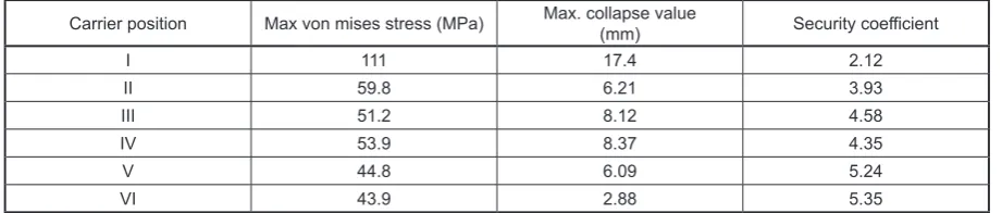
Mesh propagation is suitable for this system. Table 3 presents the maximum stress and maxi-mum collapse values achieved at structural stress analyses performed for 6 different positions rep -resenting the whole structural resistance (8 kN distributed load at Position I, 4.5 kN distributed load at Positions II and IV).
Design criteria was obtained by CATIA design.
Fig. 19. Stress analysis at Position VI
The 500 mm-diameter, 3.5 meter wide roller system is bedded with 2 flange bed units. Roller beds have a lifetime of 2.49 x 10⁹ cycle process-ing capacity. There is a shaft at the center of roller going across the length of the roller.
Different equipment can be attached on the designed fork carrier using a 100 mm box profile. The roller system differs from disc harrow with the demounting of 3 pins only. The roller system is activated by the operator by hydraulic valve. Roller pressure force is easily adjusted by chang-ing the position of the roller. The roller’s weight is 235 kg and the carrier fork’s weight is 198 kg. The roller’s weight is 67.14 kg per meter. Maxi -mum stress is on mounting pins.
Roller surface contact plates are in helical organization and in conic form applying a com-pression on the ground. We achieved a modular roller system that could be used for several ap-plications. The carrier system is also suitable for connection with different equipment.
The system is 2 times safer in operation state and minimum 4 times safer on the way. The de-sign was built through CATIA. 2D images of 3D design were achieved through CATIA Drafting
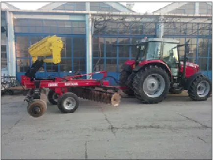
module. Sheet parts forming the design were cut by plasma shear device. The cut parts were con-nected with Under Gas Arc Welding. The roller was achieved in this way. SKF bed units were mounted on side plates welded on 100 mm x 8 mm square box hanger profiles (Figure 21). Short arms and fork carrier are presented in Figure 22. Figure 23 presents the hydraulic cylinder and roll-er system mounted on disc harrow. The system is at Position I. The roller is on way position no. VI in Figure 24. The desirable design was achieved in this way. As desired for modular roller system, a different disc harrow was used in a modular way (Figure 25).
The final design was achieved by one worker within a time period as short as 20 hours. Adap-tive roller system was mounted and field survey was performed.
The benefit desired regarding the additional roller design was achieved by the system. The de-sign created in parallel with dede-sign objectives, is ergonomic. Design objectives are reasonable and well-defined. Analysis results of the design are accurate and applicable. The system revealed out expected results in analysis.
Table 3. Stress analyses and collapse values for roller carrier system at 6 different positions
Carrier position Max von mises stress (MPa) Max. collapse value(mm) Security coefficient
I 111 17.4 2.12
II 59.8 6.21 3.93
III 51.2 8.12 4.58
IV 53.9 8.37 4.35
V 44.8 6.09 5.24
VI 43.9 2.88 5.35
Table 2. analysis report for 34% global mesh error rate
Mesh Element type Element quality (% Good)
Nodes Elements
Linear Stretch Aspect ratio
113945 407205 99.51 76.62
Table 1. The amount of motions at X and Y angles depending on hydraulic cylinder stroke. H. cylinder stroke
(mm) Positions (figure 13) H. cylinder ctroke difference Angle difference (degree) Stroke at Y angle (mm) Stroke at X angle (mm)
480–440 I-II 40 12 +212.30 +124.42
440–330 II-III 110 29 +577.16 +97.09
330–220 III-IV 110 27 +528.46 -179.36
220–110 IV-V 110 30 +417.96 -450.63
The system was used in 5000-decare land study. No damage occurred in the carrier system or in roller system.
DISCUSSION
Methodological solution used in this research enabled complete, simple, fast and successful ac-cess to the final objective. Furthermore; modular -ity brought along benefits such as identification of damaged area with design and elimination of any potential missing details. Not using methodologi -cal solution in construction is the biggest mistake and the main reason for failure and the chances of solution that go unnoticed [14].
Modern industry has focused on computer-aided analyses for achieving shorter product de-velopment time, fast marketing process, reliable and durable product design, production and op-timization (Singh, 2014). With the emergence of
Fig. 24. Mounting of disc harrow with roller system – way position.
Fig. 22. Short arms and fork carrier were produce.
Fig. 23. Roller at Position I.
Fig. 21. Roller manufacturing
faster computers and powerful FEA software, de-sign engineers can now create larger, refined and complex models and thus, offer cost-efficient, proper and informative solutions to the problems of customers. Component analysis has been re-placed by system analysis, i.e., structural analy-sis. With structural analysis, the effects of stress, shape change and location change are success-fully measured under changing load conditions.
As stated by Zahariea [27], global mesh error rate will be lower than 40%. In this research, stress analysis was performed with 34% global mesh er-ror rate. Global erer-ror rate of the study is 34%.
CATIA is a software that is commonly used in many important constructions for the reduction of stress for reorganization of damages systems. It plays a significant role in optimization studies. In research titled “Failure Investigation of the Disc Harrow Profiles and Redesigning by CATIA Analysis “conducted by Irsel et al. [6] maximum stress of 251 MPa, which was causing deforma-tion, was reduced to 124 MPa. This was achieved by attaching an additional structure of only 140 kg weight to a system around 2000 kg weight Agrawal [2] in Static Analysis, we can determine highly stressed area of truck chassis due to ap -plied load, and analytical shear stress is 13.33% less than FEA values.
Even in prototype studies, it is important to perform structural analyses of the system. Struc-tural analyses give significant information about the future of the construction. Utilization of a construction without these calculations could cause loss of life and property.
In structural stress analyses, it is necessary to use an operation center particularly in cases where the number of parts is large and their size is big, just like in the research here.
Kocer performed a design and optimization study to ensure that stress accumulation would happen on the part that could accept the damage. Kocer (2007) assessed the weight and resistance ratio and created a design that would reduce the weight of relevant part in the main gear without compromising on its resistance. In this research, the area that had the potential to get damaged was identified with the design and the current mecha -nism was improved taking the weight/resistance criteria into consideration [12].
Karaoğlu [9] studied the stress analysis of truck chassis with riveted joints. It was concluded that if it is not possible to change the side member thickness using local plates, because of increase
in weight of chassis then choosing an optimum connection plate length seems to be best practical solution for decreasing the stress values. As done by Karaoğlu, in this optimization study as well, optimal part size was determined depending on structural stress values.
Javadi and Hajiahmad [8] assessed roller adaptation in terms of agriculture. On the other hand; the roller they used was Cambridge type. It is suitable for dry soil type. Disc harrow and Cambridge roller combination is not used in ag-ricultural operations in Turkey. The roller used in this research is 130 kg/m lighter than Cambridge type roller and is in plate form. The plates contact the ground in a vertical position with intervals. Areas the plates do not contact are important for water absorption and for airing of soil.
This roller can operate on all wet grounds disc harrows can operate. A disc harrow is energy ef-ficient for soil fragmentation during primary till -age [5].
Javadi and Hajiahmad [8] created the Cam-bridge type roller combination in screw-mount-ed form. Thus; roller contact depth cannot be changed. In the design achieved in this research, the roller is deactivated by hydraulic cylinder for an instant moment. This brings many benefits in for ergonomics and functionality.
In the design created by Javadi and Hajiah-mad [8] there is a line in the middle part of the roller where the roller doesn’t contact. In this re-search, bedding was made with two flanges out -side the roller.
Utilization of roller brings benefits in agri -cultural operations. When roller is used, both the seed bed and root growth area are properly formed [15] It is also useful for the protection of the root against cold. The plant can benefit more from the soil and humidity available in compressed layer. It improves smooth surface fertility crated by rain or an irrigation process. Furthermore; roller-pro-cessed land enables more stabilized and efficient disinfection and harvesting operations.
Today, sustainability of agricultural opera-tions can be achieved with the minimization of the number of agricultural operations with the utilization of combined systems Pietola [21]. In this respect, the roller system used in this research brought benefits in every aspect.
This research achieved its purpose. It was ob-served in system production and field practices that, the defined design objectives were reason -able and appropriate.
CONCLUSIONS
1. In this research, an adaptation design was created in parallel with methodological con-struction principles through computer-aided engineering. A detail presentation was made for the computer-aided product development design process belonging to the modular roll-er system.
2. In order to obtain accurate results, it is impor-tant to study the system as a whole through structural stress analyses. The interaction be-tween the parts contacting each other may not be clearly defined in component analysis. 3. Modification study period on systems pos
-sessing CAD data is quite short. In industries where time is highly important, such as agri-cultural operations, time is important for the organization of the mechanization system. 4. Though optimization studies require a high
computer capacity, it is the most efficient way for achieving the best results in systems which are exposed to several parameters. Weight, maximum stress, global mesh error rate-oriented optimization studies are com-monly performed by CATIA. In this research, an optimal design was successfully achieved in terms of security coefficients objectives and weight limits.
5. Part-related activities of mechanism are ana-lyzed through the action of CATIA mounting design. Desirable roller activity is achieved depending on the activity of a hydraulic cylin-der with a particular stroke.
6. Analysis of stress at different positions of mechanisms is significant. Structural stress analysis of a position may not be valid for all operation limits. In this research, varying se-curity coefficients were achieved depending on the operation positions of the mechanism. 7. Systems possessing CAD data have shorter
production time and lower costs. In this re-search, metal sheets were achieved through plasma shear method with CAD data.
8. Accuracy and authenticity of mounting is sig-nificant in structural stress analyses.
9. Field surveys revealed out that, roller was able to bring desirable agricultural benefits.
10. Computer-aided engineering is the most eco-nomic and fastest way to achieve the most ef-ficient solution for all mechanisms.
11. Not using methodological solution in a design would be the biggest mistake and the basic reason for failure and loss of the chances for solution.
12. HP additional power was required for 3.5 me-ter wide roller operation. The benefit achieved in return for this amount was satisfying, indeed.
13. CATIA is commonly used in CAD data cre-ation for other engineering programs. In sev-eral programs such as ANSYS etc., the design of the system to perform the analysis is cre-ated by CATIA before the analyses.
14. Numerical simulations based on FEM, veri -fied with experiments, can be used as efficient and reliable tool in redesign of the complex construction such as bus construction that is used in our investigation [26].
15. Mesh structure forms the base for computer-aided structural stress analyses which use the finite elements method. Therefore; the use of appropriate mesh size is closely related with the accuracy of the solution of the problem. Global mesh error rate in this research was 34% for the linear element.
16. Modular systems bring about many economic benefits for several mechanizations.
Acknowledgements
In this study, the bearings were supplied by SKF Türk San. ve Tic. Ltd. Şti.
REFERENCES
1. Agrawal M.S. and Razik M. A review on study of analysis of chassis. International Journal of Mod-ern Engineering Research (IJMER), 3(2), 2013, 1135–1138.
2. Agrawal M.S. Finite element analysis of truck chassis frame, International Research Journal of Engineering and Technology (IRJET), 2(3), 2015, 1949–1956.
3. Alexandru P.H., Rudy M., Daniel V., Anton H., Ioan P. and Radu D. Modal analysis using fem of three active elements for an agricultural machine, Actual Tasks on Agricultural Engineering, Sympo -sium 43,2013, 201–209.
loam in Sweden Department of Soil and Environ-ment, Swedish University of Agricultural Scienc-es, 33, 2010, 250–256.
5. Arvidsson J., Keller T. and Gustafsson K. Specific draught for mouldboard plough, chisel plough and disc harrow at different water contents, Soil & Till -age Research, 79, 2004, 221–231.
6. Irsel G., Altinbalik T. and Can Y. Failure investiga -tion of the disc harrow profiles and redesigning by catia analysis, Applied Mechanics and Materials, 729, 2015, 181–186.
7. Irsel G. Stress analysis and design optimization with CATIA, Applied Computer Science, 12(1), 2016, 27–39.
8. Javadi A. and Hajiahmad A.Effect of a new com -bined ımplement for reducing secondary tillage operation, Internatıonal Journal of Agriculture & Biology, 8 (6), 2006, 724–727.
9. Karaoglu C. and Kuralay S. Stress analysis of a truck chassis with riveted joints, Finite Elements in Analysis and Design, 38, 2002, 1115–1130. 10. Karaçam F. and Timarci T. Stacking sequence op
-timization of composite beams with different layer thicknesses, Advances in Science and Technology Research Journal, 9(26), 2015, 7–11.
11. Krishan K. and Aggarwal L. A finite element ap -proach for analysis of a multi leaf spring using CAE tools, Research Journal of Recent Sciences, 1(2), 2012, 92–96.
12. Kocer F. Multi-disciplinary design of an aircraft landing gear using concept design and optimiza-tion techniques, Proceedings of NAFEMS World Congress, 2007, 1–7.
13. Kotari S. and Gopinath V. Static and dynamic analysis on tarta chassis, International Journal of Modern Engineering Research (IJMER), 2(1), 2012, 86–94.
14. Kutay G. Construction systematics, http://www. guven-kutay.ch/konstruksiyon/30_00_ks_giris.pdf, Turkish, 2009.
15. Loghavi M. and Hosseinpoor A. Investigating the effect of attaching roller to moldboard plow on pri -mary and secondary tillage operation, Proceeding of Second National Congress on Farm Machinery and Mechanization, Karaj, Iran, 2002.
16. Magdziak M The calculation of the nominal data of a turbine blade with the use of CAD software, MATEC Web of Conferences, 28, 2015, 1–4. 17. Marques Silva Soares J.M.C.N. Description stan
-dards of primary tillage implements, Soil & Tillage Research, 57, 2000, 173–176.
18. Nor M.A.M., Rashida H., Mahyuddin W.M.F.W., Azlan M.A.M. and Mahmud J. Stress analysis of a low loader chassis, Procedia Engineering, 41, 2012, 995–1001.
19. Ozturk I. and Bastaban S.A. Research on effect of tillage implement and machines on soil aggregation, porosity and surface smoothness in seedbed prepa-ration. International Conference on Mechanization and Energy in Agriculture, Kusadasi, Turkey, 1993. 20. Rahman R.A., Tamin M.N. and Kurdi O. Stress
analysis of heavy duty truck chassis as a prelimi -nary data for its fatigue life prediction using FEM, Jurnal Mekanikal, 26, 2008, 76–85.
21. Pietola L.M. Root growth dynamics of spring cere-als with discontinuation of mouldboard ploughing. Soil Tillage Res. J., 80, 2005, 103–114.
22. Serrano J.M., Peça J.O., Silva J.M., Pinheiro A. and Carvalho M., Tractor energy requirements in disc harrow systems, Biosystems Engineering, 98, 2007, 286–296.
23. Serrano J.M.P.J.O., Pinheiro A., Carvalho M., Nunes M., Ribeiro L. and Santos F. The Effect of -Gang Angle of Of fset Disc Harrows on Soil Tilth, Work Rate and Fuel Consumption Biosystems En -gineering 84 (2), 2003, 171–176.
24. http://www.skf.com/group/knowledge-centre/en -gineering-tools/skfbearingcalculator.html.
25. Tiwari S.K. and Joshi U.K. Stress analysis of mat-ing involute spur gear teeth, International Journal of Engineering Research & Technology (IJERT), 1(9), 2012, 1–12.
26. Vasovic I. and Ristić M., Radosavljevic M., Mi -lutinovic Z. and Kocic M. Stress analyses and op-timization of bus chassis using software package CATIA and comparative methods, Welding and Material Testing, 4, 2013, 19–22.