Strojniški vestnik - Journal o f Mechanical Engineering 54(2008)4, 274-279
UDC 621.73 Paper accepted: 15.5.2008Paper received: 16.11.2007
Experimental and Numerical Analysis of Side Forces in a
Forging Die
Andrzej Kocanda* - Piotr Czyzewski
Warsaw University o f Technology, Faculty o f Production Engineering, Poland
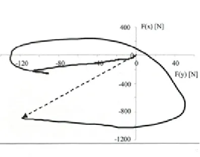
Though hot forging dies are subject mostly to forces acting in the direction o f moving tool/slider, some side forces are also developed in the die cavity according to the flow o f material in various directions. These forces would be relatively high especially in the cases ofnon-axisymmetrical or extended forgings what could result in an offset o f upper and lower dies causing geometrical inaccuracy o f the forging. This paper presents two ways o f determining side forces by means o f numerical and physical modeling. Two industrial forging processes fo r the bracket lever and the valve lever were chosen fo r the analysis. As the result, values and directions o f side forces from the beginning up to the end o f deformation stage were obtained. Hence some changes in die design or process stages which would minimize the influence o f side forces on geometrical inaccuracy o f forgings could be introduced. As an example, some ways to minimize the side forces by changing the inclination ofparting surface (bracket lever forging) or changing the positioning ofperform (valve lever forging) were shown.
© 2008 Journal o f Mechanical Engineering. All rights reserved.
Keywords: forging, forging dies, geometrical inaccuracies, numerical modeling, physical modeling
0 INTRODUCTION
Hot forging has been regarded as one of the main processing techniques due to high productivity and possibility of getting high deformation combined with very good mechanical properties of products. However, a competition from the other techniques has been quite severe and new developments in hot fo rg in g are s till very c ru c ia l. In sp ite o f organ izatio n al changes and au tom atization of processes, further developments in hot forging have been c o n n e c te d m ain ly w ith an in crease of g e o m e tric a l accu racy o f fo rg in g s and w ith approaching at least a near-net shape in the as-forged condition [1] to [4]. The savings obtained by the reduction of machining allowances and machining operations can be quite substantial. W hat more, mechanical properties o f a precision forging are usually superior to those of a forging subjected to extensive machining. This is because the forged microstructure is preserved intact in the precision forging and the fibre orientation is not disrupted.
Geometrical inaccuracies o f forging may be affected by the design o f the as-forged product, the process planning and practice o f the operational sequence, the properties of the stock material and billet, the lubricant and control o f lubrication, the
tool and machine, precision of the set-up, control o f working temperature, the finish machining and heat treatment. Precision forging is the closed die or fleshless forging. Relatively high geometrical accuracy o f forgings could be obtained also by m eans of hot forging with a flesh. However, it requires an optimization o f tool design and tool lo a d in g . In th is p a p e r som e to o lin g d e sig n considerations will be taken into account in order to minimize side movement of the different parts o f die and h en ce to m in im iz e g e o m e tric a l inaccuracy of forging.
Fast development of computer methods and com puter softw are has been very im portant in realistic m odelling o f forging processes. M any features of the forging process have already been covered. There are still some of them, such as inter stage heat treatm en t o r p o st-p ro cess therm al behaviour, which have received little attention [5], However, detailed modelling of the forging process sequences and deform ation conditions w ould provide a possibility to control heat exchange and changes in mechanical and physical properties of deformed material as well as to control exactly a flow of metal and tool loading conditions. This leads, fo r exam ple, to exact determ ination o f deformation force components including side (or
lateral) forces in the forging die [6] and [7], Side forces are relatively high in production of non- axisymmetrical or extended forgings what results in an offset of the upper and lower dies. This offset introduces geometrical inaccuracies into forgings or increased wear of some parts of die cavity.
There are many well known ways to prevent sideways movement of the different parts of die caused by side components of force [8] and [9]: ■ If possible, the parting line should be in the
same plane as the forging plane, at a right angle to the direction of deformation; this simple way w orks w ell m ain ly fo r a x isy m m etrical impressions.
■ The impression must be cut in the die block in such a way that the parting line takes into account local differences in slope angle to the forging plane in order to com pensate side component of force.
■ Forging of com ponents in pairs in order to achieve symmetry.
■ Side lock - step to counterbalance side forces. ■ Guiding of forging dies, common in close-die
forging, with cylindrical guideways, guide pins and lateral or com er guides.
M ost of the above m entioned m ethods complicate the design of forging tools and increase cost o f the tools. For that reason application of any m ethod m ust be carefully considered. So far, special experience and know-how have usually been crucial for such a tool designing. Generally, determination of directions and values of the side fo rces w ould be very help fu l in the desig n p rocedure. T his p ap er presents tw o w ays of determining side forces by means of numerical and p h y sic a l m o d elin g . Two in d u stria l fo rg in g processes for the bracket lever and the valve lever were chosen for the analysis.
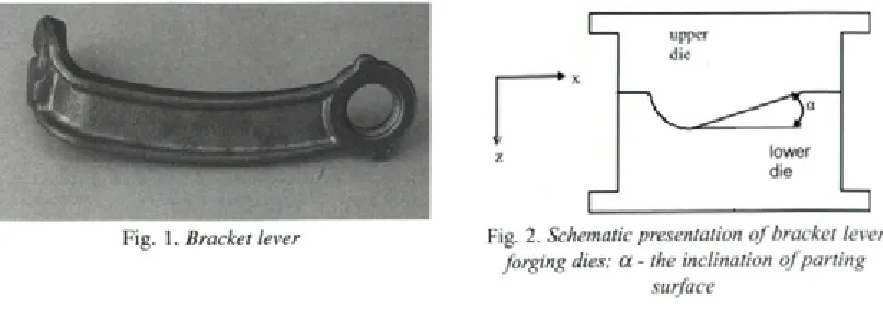
Fig. 1. B r a c k e t l e v e r
1 FORGING OF BRACKET LEVER
1.1 Numerical Modeling
MSC/SuperForge software based on finite volum e m ethod has been used in num erical modeling of the processes. Geometrical models were prepared by means of Solid Works software. The dies were assumed as stiff bodies. Combined thermo-mechanical numerical analysis has taken into account all stages and blows of the forging processes. Geometrical changes, residual stress and tem perature fields have been im ported for all subsequent stages.
The forging of the bracket lever, shown in Figure 1, was performed on a crank forging press. The lever was made of medium carbon dispersion hardening ferritic-pearlitic steel. In industrial practice, this bracket has been forged in several steps from a round bar of 20 mm in diameter.
In this paper, only the operation in the final impression has been examined. The inclination a o f p artin g su rface o f low er and u p p er dies corresponding to 0, 10, 20, 30 an 40 degrees was a variable for the analysis of forging in the final im pression (Fig. 2). Initial tem perature o f the w o rk p iece w as 1100 °C and the dies w ere preheated to 300 °C. Friction conditions were defined by Coulomb’s law with friction coefficient
0.1.
A change in the inclination a of the main part of parting surface from 0 to 40 degrees resulted in changes in the maximum side force X (direction X - Fig.2) as shown in Figure 3. Calculated force components were presented as relative values, i.e. the maximum values of side force X and forging
force Z found for the inclination a= 20 degrees were
assumed as 100%. It should be pointed out that the
Fig. 2. S c h e m a t i c p r e s e n t a t i o n o f b r a c k e t l e v e r f o r g i n g d i e s ; a - t h e i n c l i n a t i o n o f p a r t i n g
Force change 4 0 0
[%]
300
2 0 0
— - -F orce X —
/ / / / / / / /
_ _ _
-0
0 5 10 15 20 25 30 35 40 Angle a [deg]
Fig. 3. Influence o f parting surface inclination on
changes (%) in maximum values o f side X and vertical Z forces (forging o f bracket lever)
smallest side force X has been just for this angle.
Values o f the angle a low er or higher than 20
degrees caused considerable increase o f X. On the other hand, the forging force Z was the smallest
for cc= 10 degrees. Generally, the values of side
force X were equal to about 10% o f the values of forging force Z. These calculated data open the possibility to design tools in a proper way. For example, if a side force X should be as small as possible then the inclination o f parting surface would be about 20 degrees. If both forces X and Z
should be as small as possible than oc= 10 degrees
would be the best solution.
1.2 Physical Modeling
It has been essential to validate the results o f n u m e ric a l sim u latio n s and to get g re a te r confidence in the application o f side forces analysis.
Fig. 5. Upper die (UD) and lower die (LD)
arrangements on the modeling press
Fig. 4. 6-axis force transducer with vertical and
horizontal supporting elements
As for hot forging, physical modeling has been a valuable alternative to numerical modeling [10] to [14]. Physical modeling based on wax is faster, easier and less expensive than a subscale production process. To take all the advantages of using physical modeling, the modeling press and 6-axis force transducer have been used. The modeling p ress is very s tiff in both lateral and angular directions. Its elastic deflections do not influence the m aterial flow. The 6-axis force transducer consists of the upper and lower plates (Fig. 4). The transducer is mounted to the base plate of the press and the modeling tool is located on the upper plate o f transducer (Fig. 5). The upper plate o f the transducer is supported vertically by three carrying elements V I, V2, V3 and the other three elements support the plate horizontally - H I, H2, H3. Hence, the vertical force Z loads m ainly the vertical carrying elements whereas the side forces X and Y
400 i F (x )[N ]
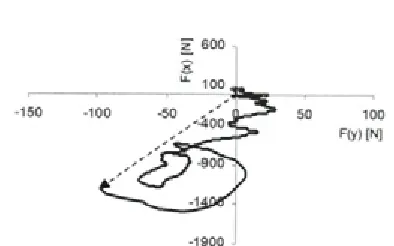
Fig.6. History o f changes in side forces X and Y
Fig. 7. History o f changes in side forces X and Y as a result o f numerical modeling; parting surface inclination 20 degrees, material for
physical modeling
load the horizontal carrying elements. Upper and lower dies for physical modeling o f bracket lever forging were made o f tool resin. Preforms were made of wax composition for which a shape of stress-strain curve was in a reasonable agreement w ith the curve for the real m aterial. D uring deformation of preform between upper and lower dies, vertical Z as well as side X and Y forces were measured. Side force X has been much higher than side force Y.
The history of changes in side forces X and Y is shown in Figure 6. It is presented in a form of changes in resulting side force in order to point out the direction and value of the force from the beginning up to the end of deformation. Broken line shows the resulting side force just at the end of forging. It has changed the direction over 300 degrees during the whole forging process. Hence,
the sid e lo ck d esig n in the die should
co u n terb alan ce the side force from d ifferen t directions. The results shown in Figure 6 were in a q u ite good ag re e m e n t w ith the re su lts o f num erical sim ulation carried out for modeling material (Fig. 7). The direction of the final resulting side force is alm o st the sam e as in physical
Z
Fig. 9. A forging with overlapping (case I) and a
forging without any defect (case II)
modeling. There are some differences between these two curves in the initial stage of deformation when the forces are relatively small. It could be caused by slight differences in placem ent o f preforms and friction conditions.
2 FORGING OF VALVE LEVER
Forging process of valve lever was analysed by means of results of numerical modeling. The process was performed on a forging hammer. Initial temperature of preform was 1100 °C and the dies were preheated to 250 °C.
The upper and the lower dies were designed as to have fuller, blocker and finisher impressions (Fig.8). The full process consisted of the following stages:
• Initial upsetting (1 blow), • Fullering (2 blows),
Fig. 8. Pre-forms placed in the blocker impressions o f the lower dies fo r forging o f valve levers
Fig. 10. Changes o f the lateral force in X direction fo r two cases o f preform orientation
F ig .ll. Changes o f the lateral force in Y direc
tion fo r two cases o f preform orientation
• 90° counter-clockw ise (case I) or clockwise
(case II) rotation o f preform and additional fullering (2 blows),
• Forging in the blocker impression to get the general final shape (3 blows),
• Forging in finisher impression to get the final overall shape (1 blow).
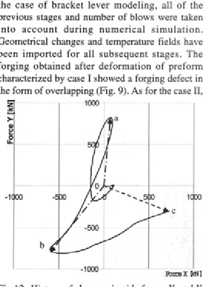
A s an exam ple, fo rg in g in the b lo ck er impression has been chosen for analysis [7]. As in the case o f bracket lev er m odeling, all o f the previous stages and number o f blows were taken in to a c c o u n t d u rin g n u m e ric a l s im u la tio n . Geometrical changes and temperature fields have been im p o rted fo r all su b seq u en t stages. The forging obtained after deform ation o f preform characterized by case I showed a forging defect in the form of overlapping (Fig. 9). As for the case II,
Fig. 12. History o f changes in side forces X and Y
in finisher impression o f die (case II); a,b,c -high values o f the resultant side forces at differ
ent stages o f the forging process
the forging did not show any defect. Figures 10 and 11 present changes in lateral forces X and Y as a function of upper die stroke (third blow). The lateral forces have been much smaller for the case I than for the case II. It means that the necessity to change the preform positioning for getting the forging without overlapping lead to a considerable increase in values o f lateral forces (case II). What more, the directions o f the highest resulting side forces were different during the course o f the process as shown in Figure 12 for the finisher impression (case II). It means that the guiding of the u p p er and lo w er dies is necessary in the a n a ly se d fo rg in g p ro c e ss fo r g e ttin g a hig h geometrical accuracy of forgings.
3 CONCLUSIONS
* T here are m any w ays to prevent sidew ays movement of upper and lower dies caused by side fo rces. C h o ice o f the w ay w ould be supported by the results of numerical modeling. ■ Numerical modeling of the bracket lever forging
for various inclinations of the parting surface has been helpful in minimizing the lateral force. The lowest values o f lateral force and forging forces have been found for the inclination angle o f about 10 degrees.
* Necessity to avoid the overlapping defects in valve lever forging resulted in a considerable increase in values of lateral forces.
■ The ratio of lateral to vertical forces was up to ab o u t 10% in the tw o fo rg in g p ro cesses analyzed in this paper.
Acknowledgement
This research work has been financially supported by the Ministry of Science and Higher Education, grant no. 4 T07D 037 29. The authors also w ish to th an k g ra d u a te stu d en ts M. Andrzejewski, D. Lukasiewicz and R. Warmiak for their assistance in physical modeling.
4 REFERENCES
[ 1 ] Kudo, H. Towards net-shape forming. Journal of Materials Processing Technology, voi. 22, no. 3, 1990, p. 307-342.
[2] Douglas, R., Kuhlmann, D. Guidelines for p recisio n hot fo rg in g w ith ap p licatio n s.
Journal o f Materials Processing Technology,
voi. 98, no. 2, 2000, p. 182-188.
[3] Balendra, R. Net-shape forming: state of art.
Journal o f Materials Processing Technology,
voi. 115, no. 2, 2001, p. 172-179.
[4] B ehrens, B .-A ., D oege, E., R einsch, S., Telkamp K., Daehndel H., Specker A. Precision forging process for high-duty autom otive
components. Journal o f Materials Processing
Technology, voi. 185, 2007, p. 139-146. [5] Hartley, P , Pillinger, I. Numerical simulation
of the forging process. Computer Methods in
Applied Mechanics and Engineering, vol. 195, no. 48-49, 2006, p. 6676-6690 .
[6] Kocanda, A., Czyzewski, R, Krzyszkowski, P. Some developments in analysis of lateral
forces and cyclic loading with relation to
forging dies. Proceedings o f the 8th ICTP
“Advanced Technology o f Plasticity”, Verona, 2005, p. 171.
[7] Kocanda, A., Czyzewski, P. An influence of some process parameters on lateral forces in
forging dies. Computer Methods in Materials
Science, voi.7, 2007, p. 208-211 .
[8] Wasiunyk, P. Hot Forging. WNT, Warszawa,
1975. (in Polish).
[9] L ange, K. Handbook on metal form ing.
McGraw-Hill, 1985.
[10] Wanheim, T., Maegaard, V., Danckert, J. The p h y sical m o d ellin g o f p lastic w orking
processes. Advanced Technology o f Plasticity,
Proc. 1st Int. Conf. on Technology o f Plasticity, vol. II, Kyoto, 1984, p. 984-996. [11] Wanheim, T., Danckert, J. Combined physical
and numerical modelling of metal forming
processes. Advanced Technology o f Plasticity,
Proc. 2nd Int. Conf. on Technology o f Plasticity, vol. II, Stuttgard, 1987, p. 29-36.
[12] Metals handbook, 9th Ed., voi. 14, Forming
and Forging, ASM Int., 1988.
[13] H engan, O. Finite element analysis and
experim ental investigation o f stiffness characteristics o f forming presses and forging o f turbine aerofoil components. PhD Thesis, University of Strathclyde, 2001.
[14] Zhan, M., Liu, Y., Yang, H. Physical modeling of the forging of a blade with a damper platform
using plasticine. Journal of Materials Processing
Technology, vol. 117, 2001, p.62-65.
[15] Chodnikiewicz, K., Kocanda, A., Prejs, T. Hydraulic press and force transducer for physical modelling of bulk metal forming.
Proceedings o f the “Baltic Sea Metal Forming and Cutting Seminar BAM FAC ‘98", Vilnius,