0 INTRODUCTION
Structural foams (SF) are multi-layer materials consisting of two integral skins and a cellular core [1] and [2] This structure combines the lightness of the cellular core with the strength of dense unfoamed skins. An important characteristic of this sandwich structure is its high specific flexural stiffness/strength ratio. For this reason, the main use of this structure is in engineering and load-bearing applications [3]. One well-known use of the SF of glass-filled polypropylene (PP) was in the tanks of domestic washing machines [4].
Thermoplastic SF may be produced by different injection moulding techniques. Commonly, SF are manufactured using a low pressure short-shot process (typically 65 to 90% of the impression volume), in which an amount of melt containing dissolved gas (usually chemical blowing agents (CBA)) is injected to partially fill the impression [5]. The expansion of the blowing agent guaranties the fulfilment of the cavity. This process has advantages including the possibility of production of complex thick and large parts without sink marks; the development of low levels of internal stresses; a lower tendency to warpage and distortion; and the requirement of reduced clamping forces due to the low impression pressures, typically below 4 MPa [2] and [6]. Conversely, the cycle time is longer, the surface finish is poorer, there can be gas emission
during processing, and reprocessing is more complex [3].
The complex inter-relationship between structure properties and moulding conditions have been discussed in depth by Ahmadi et al. [5]. They concluded that the uniformity and fineness of the cellular core are greater when using high injection rates combined with low melt and mould temperatures. The degree and variability of irregularities across the surface of SF mouldings are highly dependent on the extent of flow into the moulding cavity and the processing conditions.
Surface roughness is reduced mainly by increasing the shot weight that influences the degree of expansion and, therefore, the overall density of the moulding. Excessive foaming in the cavity results in considerable rupture at the melt flow front and, consequently, a lower surface finish. Increasing the mould temperature allows more time for relaxation of surface defects before cooling is completed; a slightly lower roughness is thus achieved [7].
It is difficult to control the cell size and cell size distribution [8] and [9]. The poor uniformity of cell distribution in mouldings injected with the low pressure process is largely attributed to the deficient mixing of the CBA and the polymer.
The size and density of the cells, the skin thickness and the density profile across the thickness have a considerable effect on the mechanical properties of the resulting foams. CBA concentration and injection
The Influence of Processing on the Aesthetic, Morphological and
Mechanical Properties of Structural Foam Mouldings of
High-Impact Polystyrene
Esteves F.R. – Carvalho T.A. – Pouzada A.S. – Martins C.I.
Fantina Rosa Esteves – Tiago Alexandre Carvalho – António Sérgio Pouzada – Carla Isabel Martins* Institute for Polymers and Composites/I3N, University of Minho, Portugal
The production of large plastic parts, in small series and at low cost, requires the development of alternative tools and materials. Structural foams (SF) are an appropriate solution, when the production of thicker parts with superior properties is specified. They allow the production of lightweight parts with high stiffness and excellent dimensional stability, due to their sandwich-like structure consisting of a cellular core and two solid skins. The porous core is the result of the addition of a blowing agent in the polymeric matrix. These materials are applied in the urban furniture, automotive, nautical and aerospace industries. The most commonly used process to produce SF is low pressure foam moulding, which is a short-shot process, with impression pressures below 4 MPa. Therefore, the use of hybrid moulds with moulding blocks obtained by rapid prototyping routes is seen as a viable alternative for SF injection moulding.
pressure are the main factors influencing foam quality. The mould temperature has a significant effect on the skin thickness; back pressure also influences skin thickness, cell size and foam density. Finally, the mould and melt temperatures have negligible effects on the cell density [3].
The flexural stiffness and the impact strength increase with the moulding thickness. The flexural properties depend on whether the SF-layered structure is symmetric or asymmetric [10] and [11] On impact, the energy required for crack initiation and the total energy for failure are substantially reduced by the occurrence of microcells in the outer skins that act as stress raisers [5] and [7]
Injection moulding of SF is a low pressure process, ideal for the production of large area parts. Therefore, it is a viable candidate for light moulding tools, as is the case of hybrid moulds [12]. In these tools, the moulding blocks are produced by rapid prototyping and tooling (RPT) with routes such as the vacuum casting of epoxy composites. Typically, these blocks are produced in a composite of epoxy with aluminium powder, which has the advantages of easy manufacturing and short delivery time [13]. The main disadvantages, when compared with conventional steel moulds, are worse thermal and mechanical behaviours, shorter useful lifetimes of the moulding blocks and longer cycle times, which means that this processing option is recommended for a limited number of parts [12].
Acrylonitrile butadiene styrene (ABS) is known for displaying a well-balanced set of properties that ensure correct dimensional stability, excellent surface finish, superior impact strength and metallization characteristics [14]. In the form of SF, applications including furniture, loudspeaker boxes, telephone junction boxes, sprinkler housings, television housings, other housings, or automotive back seats [15]. High-impact polystyrene (HIPS) features many of the ABS properties at a lower price and has a similar processing character.
This study focuses on the morphological and mechanical properties of HIPS-SF injection mouldings. The flexural and impact behaviours of HIPS-SF are related to its morphological and physical parameters, such as skin ratio and density. Finally, the experimental results of the flexural stiffness are compared to models proposed by Barzeraghi et al. [16].
1 EXPERIMENTAL
1.1 Raw Materials
High impact polystyrene (HIPS) from BASF, Korea, with a specific gravity of 1.05 Mg·m–3 and MFI of 10.95 g / 10 min (200 ºC / 5 kg) was used together with 2 wt% of an endothermic CBA, Tracel IMC 4200SP, from Tramaco, Germany, with a decomposition temperature in the range of 160 to 220 ºC, for the production of HIPS-SF.
1.2 Injection Moulding
Centred gated discs of 155 mm in diameter and 5 mm in thickness were processed with an Engel Victory Spex 50 injection moulding machine (Engel, Austria). The mouldings were produced using two mould material combinations for the moulding blocks (core and cavity): a conventional steel mould configuration and a hybrid mould as depicted in Fig. 1. The hybrid mould has an insulating plate (resin filled with glass fibres) in the injection side and a moulding block in the ejection side, made in a composite of epoxy Biresin L74 filled with 60 wt% aluminium powder. This moulding block was produced by vacuum casting and machined to the final geometry of the part, following the standard routine described in [17].
The mouldings were injected with 90% of the mould filling, and the complete filling was promoted by the CBA expansion. Various processing conditions were used, as shown in Table 1.
Fig. 1. a) mould structure, b) moulding, c) steel moulding block, d) hybrid moulding block
a)
b)
Table 1. Injection moulding processing conditions Parameter
Tinj
Hybrid Steel
Injection temperature [ºC]
200 220 240 220
Mould temperature [ºC] Core T1 45 75
Cavity T2 50 75
Cooling time [s] tcool 180 80
Flow rate [cm3/s] Q 60
The moulding code is an alphanumeric value, e.g., H200, where the letter means that the material was injected in the hybrid mould (H) or in the steel mould (S), and the number indicates the injection temperature, in this example 200 ºC.
1.3 Mould Monitoring
The two halves of the mould were instrumented with Resitec type J, TC.002 thermo-couples (Resitec, Portugal): one was placed in the injection side at 2 mm from the moulding surface and at 30 mm from the gate (T1), and the other in the ejection side, at the same position (T2) (Fig. 2). The signals were acquired and recorded with a Priamus Multi DAQ 8101A data acquisition system.
Fig. 2. Hybrid mould configuration and setup of thermocouples: 1-steel injection plate, 2-insulating plate, 3-steel ejection plate,
4-moulding block (resin or steel)
These thermocouples were placed in these positions to allow the monitoring of the mould temperature, and to ensure the symmetric development of the moulding structure [10].
1.4 Morphological Analysis
The effect of the processing conditions on the microstructural development of the HIPS-SF parts was assessed using an Olympus BH-2 optical microscope (Olympus, Japan) coupled with a Leica DFC 280 digital camera (Leica, Germany). Thin slices of about 10 µm were cut from samples using a microtome (Leitz, Germany) at 30 mm from the gate as shown in Fig. 3. The slices were placed between a glass slide and cover glass after immersion in Canada balsam.
Measurements of the skin ratio were made throughout the section. The skin ratio is defined as
the ratio between the sum of the thickness of the two skin layers and the overall thickness of the samples, expressed as a percentage.
Fig. 3. Sample location for the morphological analysis; insert refers to the slices made along the flow path (S - skin, C - core)
To verify the existence of crushed cells and/or cells of small dimension in the skin, an observation was performed in a NOVA 200 Nano SEM ultra-high resolution field emission gun scanning electron microscope (FEG-SEM), (FEI, USA). The samples were cryo-fractured, sputter-coated with gold, and fixed in a support with carbon tape adhesive.
1.5 Gloss
The gloss measurements were carried with a BYK-Gardner micro-TRI-glossmeter (BYK, USA) calibrated with a black glass standard according to the ASTM D523-85 standard. A minimum of five specimens for each condition and at three different locations in the sample were used to determine the average gloss and respective standard deviation. For each type of surface, the measuring angle was 85º according to the ASTM standard. The gloss ratings measured by this test method are obtained by comparing the specular reflectance from the specimen to the black glass standard. The aim of gloss measurements was to estimate how the type of the mould (steel moulding block, hybrid moulding block) and processing conditions influence the gloss of injected parts.
1.6 Roughness
determined. Five measurements for each condition were carried, and each sample was measured in five different locations.
1.7 Density
The density was measured using the impulsion method (Archimedes principle) according to the ASTM standard D 792-00. A Scaltec SBC 31 analytical balance (Denver Instrument, Germany) with capacity of 220 g and accuracy of 0.0001 g was used. A density measurement kit was used together with the balance, and the liquid of reference was isopropanol. Five measurements were performed for each condition, and an average density value was calculated.
1.8 Flexural Testing
The flexural tests were performed at room temperature with the three-point support Pouzada and Stevens test method [19]. The testing apparatus was mounted in an Instron 4505 universal testing machine (Instron, USA), in compression mode. The samples were placed on the support base, and the load was applied at the centre of sample using a crosshead speed of 5 mm/ min. A maximum displacement of 5 mm was imposed, guaranteeing that the sample behaved as a plate in the elastic range (Fig. 4). The flexural stiffness data hereafter are the average of five tests.
Fig. 4. Schematic of the three-point support flexural test [19]
For isotropic materials that can be mechanically characterized in terms of a modulus (E) and a lateral
contraction ratio (ν), the flexural stiffness is defined as [19]:
C= E
−
(1 ν2). (1)
For small deflections of a circular disc, the flexural stiffness, C, can be analytically expressed in terms of the slope of the F/δ trace and the geometrical parameters of the flexural test. In this case, it is applicable the Bassali equation:
C R B v
h S
=3
4
2
3 0
( ) ,
π (2)
where h is the sample thickness, R is the radius of the 3-point support circumference (93.5 mm), B(ν) is a function of Poisson’s ratio, which in the range of 0.3 to 0.45 has an average value of 5, for HIPS. The slope, S0, is the corrected slope of the load versus displacement curve when the support points are not on the periphery of the disc.
In the cases of samples overhanging the supports, it is necessary to consider the difference between the radius of the sample and the radius of the support
circumference. Given the overhang length ΔR, the
support diameter D, and the measured slope, S, the corrected slope, S0, is calculated as [19]:
S S
e DR
0 4 1
0 59 1 1
=
−
+
−
.
.
.∆ (3)
1.9 Impact Test
The impact tests were performed at room temperature with the CEAST 9350 Fractovis Plus (CEAST, Italy) using the following setup: impact weight of 15.765 kg and drop height of 700 mm, leading to an impact speed of 3.705 m·s-1. The tests were performed according to the European Standard EN ISO 6603-1.
2 RESULTS AND DISCUSSION
2.1 Mould Monitoring
The mould monitoring data of the hybrid and steel moulds are depicted as examples in Figs. 5 and 6, respectively.
of temperature after the injection of the material is observed. The temperature starts decaying slowly until the cooling of the sample is completed.
Fig. 5. Evolution of temperature in the core (T1) and cavity (T2) sides of the hybrid mould during the injection cycle of
HIPS-SF, for Tinj = 220 ºC
The temperatures in the hybrid mould (T1 and T2) have a significant difference when the cycle starts and during cooling. This results from the different thermal conductivities of the mould materials used in the core and cavity, which make the cooling rate more difficult to control in the two sides of the mould.
In the steel mould, the temperature in the core and cavity side is similar because the mould materials have the same thermal properties.
Fig. 6. Evolution of temperature in the core (T1) and cavity (T2) sides of the steel mould during the injection cycle of HIPS-SF, for
Tinj = 220 °C
2.2 Morphological Characterization
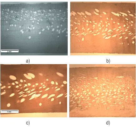
The typical structure obtained in the HIPS-SF injection moulding is depicted in Fig. 7. The structure is characterized by two outer solid layers (skin) and a cellular core. Depending on the type of mould
used, different microstructures are developed. With the hybrid mould, there is the development of an asymmetric sandwich structure (Figs. 7a to c), and in the case of the steel mould the structure is symmetric (Fig 7d). This may be related to the variation of the mould temperature during the injection cycle, as shown in Figs. 5 and 6.
a) b)
c) d)
Fig. 7. Polarized light microscopy: influence of the injection temperature on the microstructure of HIPS-SF at a) H200, b)
H220, c) H240, d) S220
The mouldings produced in the hybrid mould also have larger cells with a variety of shapes, as compared to the steel mould (Fig. 8). At the core, the cells of the hybrid mouldings are approximately
200 μm in diameter, whereas the cells of the steel mouldings are only 80 μm. The cells dimensions
are decreasing from the centre to the skin due to the difference in the melt temperature and are distorted as a result of the fountain flow. With the increase of the injection temperature, this phenomenon becomes more pronounced. Furthermore, the growth of the cell size is evident with the increase of the temperature, due to the lower viscosity and less resistance to the cell growth [10].
It is confirmed in the SEM images the presence of crushed cells and nanopores in the skin (Fig. 9), which affects the mechanical properties, mainly in impact, as is shown next.
a)
b)
Fig. 8. SEM view of the core of the moulding injected in: a) hybrid mould, b) steel mould at 220 ºC
Fig. 9. SEM view of the skin of HIPS-SF (H220) with crushed cells and nanopores
2.3 Aestethics Analysis
The surface roughness and, thus, the gloss of plastics parts are key characteristics that affect the moulding aesthetics.
The gloss and roughness (Ra) of the moulding
blocks and plastics mouldings are summarised in Table 2 and Table 3, respectively.
Table 2. Roughness and gloss of the moulding blocks Mould Ra [μm] Gloss [%] Hybrid moulding block 6.96 (1.32) 9.07 (2.24) Steel moulding block 1.81 (0.40) 59.52 (4.74) Standard deviation values are in parentheses.
Table 3. Effect of the moulding parameters on the gloss and roughness of HIPS-SF
HIPS-SF HIPS
Ra [μm] Gloss [%] Ra [μm] Gloss [%] H200 1.02 (0.24) 1.69 (0.11) 1.07 (0.19) 1.79 (0.15) H220 1.10 (0.06) 1.56 (0.16) 2.22 (0.22) 0.98 (0.07) H240 1.99 (0.38) 0.93 (0.24) 3.70 (0.78) 0.56 (0.17) S220 0.89 (0.11) 14.74 (2.74) 0.60 (0.17) 47.92 (2.56) Standard deviation values are in parentheses.
The surface finish of the moulding blocks and the processing conditions affect the gloss of the corresponding surface of the moulded parts. The hybrid mould blocks have Ra higher than the steel
blocks. Consequently, the parts produced in the hybrid mould have higher Ra and display lower gloss due to
the replication of the surface roughness of the mould in the plastic part [20].
The roughness increases with the increasing injection temperature. This may result from the lower viscosity of the material enabling better replication of the rough surfaces [20] and [21]. HIPS-SF presents lower Ra and higher gloss because the pressure required to fill the impression with the expansion of the blowing agent is lower than in conventional mouldings of HIPS [6]. Thus, the replication with HIPS-SF is less accurate than non-foamed HIPS.
2.4 Flexural Behaviour
Table 4. Flexural stiffness, skin ratio and density of HIPS-SF, for various processing conditions
Flexural stiffness [MPa] Skin ratio [%] Density [Mg·m-3]
SF 100% SF SF 100%
H200 2277.36 (119.47)
2614.40 (164.92)
44.86 (3.7)
0.94 (0.014) 1.028
H220 2236.76 (88.49)
2568.45 (14.25)
49.36 (5.6)
0.89 (0.005) 1.029
H240 2132.03 (135.77)
2542.27 (51.00)
43.73 (7.5)
0.88 (0.002) 1.027
S220 2081.14 (190.00)
2326.56 (93.82)
29.55 (2.6)
0.86 (0.004) 1.028
Standard deviation values are in parentheses.
In general, increasing the injection temperature decreases the skin ratio and the density. The density, being related with the amount and distribution of material, corresponds to the distribution of the applied loads [22]; therefore, as it decreases, the flexural stiffness also decreases. In non-foamed mouldings, the material available to support the flexural loads is greater than in foamed mouldings, which have a porous core; therefore, its stiffness is higher [11]. The HIPS-SF mouldings in the hybrid mould are slightly stiffer than in the steel mould, due to the larger skin ratio and higher density.
2.5 Impact Behaviour
A typical drop weight impact test graph for HIPS-SF is depicted in Fig. 10.
The peak force, Fp, observed corresponds to the moment the material yields and enters the plastic regime. From this point onward, it is not possible to recover the strain and thus the moulding is no longer useful for service. The area below the first peak corresponds to the energy absorbed up to this moment (peak energy, Up).
Fig. 10. Typical output obtained in falling weight tests of HIPS-SF mouldings
A typical fracture of an HIPS-SF moulding is shown in Fig 11.
Fig. 11. Fractured HIPS-SF mouldings
The observation of the failed mouldings suggests a ductile fracture, as the crack did not propagate along the radial direction.
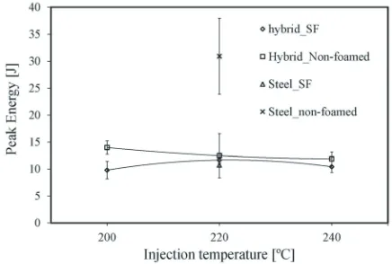
The effect of the injection temperature on the peak energy is shown in Fig. 12.
Fig. 12. Falling weight impact peak energy of HIPS-SF
As with the flexural properties of HIPS-SF, the resistance to the impact of falling weights is also influenced by the density and the skin thickness. In addition, defects on or near the surface are thought to have a significant role in determining the peak energy. Raising the injection temperature decreases the peak energy, in accordance to the density reduction.
The occurrence of microcells near the outer skins may affect the integrity of these outer layers, acting as stress raisers, thus decreasing the impact resistance. The resistance to crack propagation is worsened by the formation of large non-uniform cells at the core of the mouldings, becoming increasingly evident at higher melt temperatures [7].
2.6 Model Prediction
morphological characteristics are known. Barzegari et al. proposed a model to predict the flexural behaviour starting from approximations to the density profile [16]. To simplify notations, they used normalized parameters, as relative density R, and relative thickness, r:
ρ ρ ρ ρ c s f s R R
= 1, = 2, (4)
δ δ δ δ δ δ c f s f c f r r
= , = −1 = −1 , (5)
where ρf, ρs, ρc are densities of foam, skin and core,
respectively, and δf, δs, δc are thicknesses of foam,
skin and core, respectively.
Some of those density variation approaches are shown in Fig. 6. These cross-sections represent an approximation of the density profile across the thickness. In this study, the models of Fig. 13 c and d
are analysed.
Fig. 13.Different approaches of density profiles for SF [16]
The core density was calculated using the following equations: ρ ρ ρ ρ δ δ δ δ c s f s st f st f = − − − 1 1
, (6)
δst=δs1+δs2, (7)
where δst is the total skin thickness.
Model c) assumes that the core density reaches a minimum at the centre of the beam with a linear variation in the core part. Thus, the normalised flexural modulus is obtained by:
E E
r R R
f
s
= −1 − −
10 4 3
3
1 1 2
( ) . (8)
In Model d), the cross-section of Fig. 13d is decomposed into a three-layered structure. It assumes that the skin density decreases linearly to the core density. An intermediate layer, t, is considered, and the core density is uniform. Thus, the normalized flexural modulus is:
E
E r R r t R R
rt R R t
f s = −
(
−)
−(
− −)
− − − − −1 1 2
3
2 2 10 4
3
12 2 1 12
2
1 1
2 3
( −−3R R1− 12). (9)
Upon using these models, the predicted flexural stiffness can be calculated. The predictions using Model d) are not too far from the experimental results, with a maximum error of 9%, whereas with Model c), the maximum error is about 14%, as shown in the Table 5.
Table 5. Prediction of flexural stiffness
Experimental [MPa]
Predictions CModel c)
[MPa]
CModel d) [MPa] Δ
Cc) [%] Δ
Cd) [%] H200 2277 2582 2489 11.78 8.51 H220 2237 2529 2422 11.54 7.64 H240 2132 2490 2350 14.38 9.27
S220 2081 2235 1987 6.88 4.51
3 CONCLUSIONS
The processing conditions influence the aesthetic, morphological and mechanical properties of HIPS-SF mouldings injected in hybrid moulds and conventional steel moulds.
The mouldings produced with hybrid moulds have reduced gloss due to their higher roughness. The injection temperature has influence on the skin ratio and shape of the cells. With an increase of the injection temperature, there is an increase of the cell size due to the lower viscosity and a decrease of the skin ratio and density, which causes the flexural stiffness also to decrease.
The mouldings subjected to impact show a ductile behaviour, and the peak energy in the falling weight test decreases with the increasing injection temperature.
4 ACKNOWLEDGEMENT
This work was developed with the support of the Portuguese Foundation for Science and Technology under the strategic project PEst-C/CTM/ LA0025/2013. The authors acknowledge the support of the Portuguese program QREN, which funded contract 2010/013307 for project ‘Hybridmould 21’.
5 REFERENCES
[1] Malloy, R.A. (1994). Plastic Part Design for Injection Molding: An Introduction, Hanser Publishers, New York.
[2] Rosato, D.V., Rosato, D.V., Rosato, M.G. (2000).
Injection Molding Handbook, 3rd ed. Kluver Academic Publishers, Boston/Dordrecht/London, DOI:10.1007/978-1-4615-4597-2.
[3] Barzegari, M.R., Rodrigue, D. (2009). The effect of injection molding conditions on the morphology of polymer structural foams. Polymer Engineering and Science, vol.49, no. 5, p. 949-959, DOI:10.1002/ pen.21283.
[4] Oghoubian, R., Smart, J. (1990). Out-of-plane bending of faceted cylinder end plates. The Journal of Strain Analysis for Engineering Design,. vol. 25, no. 2, p. 95-101, DOI:10.1243/03093247V252095.
[5] Ahmadi, A.A., Hornsby, P.R. (1984) Moulding and Characterization studies with polypropylene structural foam. I. Structure-property interrelationships. Plastics and Rubber Processing and Applications, vol. 5, no. 1, p. 35-49.
[6] Nogueira, A.A., Martinho, P.G., Brito, A.M., Pouzada, A.S, (2011). A study on the mouldability of technical parts using hybrid moulds and structural foams, Bártolo, P.J. (ed.): Innovative Developments in Virtual and Physical Prototyping, CRC Press/Balkema, London, p. 399-404.
[7] Ahmadi, A.A., Hornsby, P.R. (1985). Moulding and characterization studies with polypropylene structural foam. II. The influence of processing conditions on structure and properties. Plastics and Rubber Processing and Applications, vol. 5, no. 1, p. 51-59. [8] Mark, J.E., (ed.) (2007). Physical properties of
polymers handbook. 2nd ed., Springer Science + Business Media, New York.
[9] Kamal, M.R., Isayev, A.I., Liu, S.-J. (2009).
Injection Molding - Technology and Fundamentals,
White J.L. (ed.) Carl Hanser Verlag, Munich, DOI:10.3139/9783446433731.
[10] Tovar-Cisneros, C., González-Núñez, R., Rodrigue, D. (2008). Effect of mold temperature on morphology
and mechanical properties of injection molded HDPE structural foams. Journal of Cellular Plastics, vol. 44, no. 3, p. 223-237.
[11] Barzegari, M.R., Rodrigue, D. (2009). Flexural behavior of asymmetric structural foams. Journal of Applied Polymer Science, vol. 113, no. 5 p. 3103-3112, DOI:10.1002/app.30335.
[12] Pouzada, A.S. (2009). Hybrid moulds: a case of integration of alternative materials and rapid prototyping for tooling. Virtual and Physical Prototyping, vol. 4, no. 4, p. 195-202, DOI:10.1080/17452750903438676. [13] Bareta, D.R., Pouzada, A.S., Costa, C.A. (2007).
The effect of rapid tooling materials on mechanical properties of tubular mouldings. International Conference on Polymers & Moulds Innovations. Ghent. [14] Campo, E.A. (2006). The Complete Part Design
Handbook for Injection Molding of Thermoplastics.
Hanser, Munich.
[15] Hough, M., Dolbey, R. (1995). The Plastics Compendium, Rapra Technology, Shrewsbury.
[16] Barzegari, M.R., Rodrigue, D. (2007). The effect of density profile on the flexural properties of structural foams. Polymer Engineering & Science, vol. 47, no.9, p. 1459-1468.
[17] Vasconcelos, P.V., Jorge Lino, F., Neto, R.J. (2004). Importance of the vacuum in rapid tooling of polymeric-based moulds. International conference on Rapid Product Development, Marinha Grande.
[18] Ferreira, E.C., Costa, M. F., Laranjeira, C.R., Oliveira, M.J, Pouzada, A.S. (2004). Comparative study, by optical techniques of the interface polymer/steel in replication conditions. Advanced Materials Forum II, vol. 455-456, p. 467-471, DOI:10.4028/www. scientific.net/MSF.455-456.467.
[19] Pouzada, A.S., Stevens, M.J. (1984). Methods of generating flexural design data for injection moulded plates. Plastics and Rubber Processing and Applications, vol. 4, no. 2, p. 181-187.
[20] Oliveira, M.J., Brito, A.M., Costa, M.C., Costa, M.F. (2006). Gloss and surface topography of ABS: A study on the influence of the injection molding parameters.
Polymer Engineering & Science, vol. 46, no. 10, p. 1394-1401, DOI:10.1002/pen.20607.
[21] Vasconcelos, P.V., Lino, F.J., Neto, R.J., Paiva, R. (2006). Design epoxy resins based composites for rapid tooling applications. 5th International Conference on
Mechanics and Materials in Design, Porto.
[22] Lanz, R.W., Melkote, S.N., Kotnis, M.A. (2002). Machinability of rapid tooling composite board.


![Fig. 4. Schematic of the three-point support flexural test [19]](https://thumb-us.123doks.com/thumbv2/123dok_us/8950909.1860277/4.586.91.238.451.650/fig-schematic-point-support-flexural-test.webp)

![Fig. 13. Different approaches of density profiles for SF [16]](https://thumb-us.123doks.com/thumbv2/123dok_us/8950909.1860277/8.586.60.273.351.495/fig-different-approaches-density-profiles-sf.webp)
