Azadeh Sharafibadr
∗1and Zahra Nilforoushan
†21,2Faculty of Engineering, Kharazmi University, Tehran, Iran.
ABSTRACT ARTICLE INFO
We consider the problem of finding the localization of radioactive source by using data from a digital camera. In other words, the camera could help us to detect the direction of radioactive rays radiation. Therefore, the outcome could be used to command a robot to move to-ward the true direction to achieve the source. The cess of camera data is performed by using image pro-cessing and computational geometry algorithms. And the robot is looking for the source in a space with ge-ometrical obstacles. Lots of radioactive accidents daily occur all over the world. During the radiography, the radioactive source is sometimes thrown out from its pro-tection layer and the radiographer has to look for it in the space around. This would have lots of irreparable costs. Thus, it seems necessary to make a robot which could search the radioactive source intelligently.
Article history:
Received 12, July 2018
Received in revised form 5, April 2019
Accepted 12 May 2019
Available online 01, June 2019
Keyword: Dosimetry, Autonomous robot, Convex hull Hough transform.
AMS subject Classification: 05C79.
∗Corresponding author: A. Sharafibadr. Email: std [email protected] †[email protected]
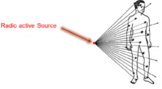
Figure 1: Exposure of radiographers to the radioactive source
1
Introduction
Millions of people throughout the world are working in radioactive contaminated environ-ments, most of whom are not much aware of the radiation dosage they receive.
Owing to the increasing expansion of peaceful usage of ionizing radiation in various in-dustrial, medical, agricultural, educational and research centers, and with respect to the fact that just in Iran, more than twenty thousand radiographers in various branches of radiation materials and radiation devices are working in a wide range of activities, these people are always at risk of such these activities.
In order to follow the protection standards against radiation and to pursue the recom-mended national and international limits, we need to measure the individual and envi-ronmental dosimetry, and its absorption into the materials; furthermore, it is essential to estimate the biological damage caused by a beam. That is why it’s very important to improve the quality of dealing with the health physics issues.
Ionizing rays threaten the human body in various ways mostly externally, or after entering the body. Figure1.
Environmentally speaking, controlling safe working conditions in radioactive environ-ments, detection of radiation-exposure incidents, identification of the dosage received during an accident, obtaining the information required for epidemiological study of work-ing with radiation are the most significant factors, [4].
The existing dosimeters are useful to find the place of radioactive source until we know its location limitation, and if we do not know it, we will have difficulties.
On the other hand, the radiographers negligence is the main factor behind many radiation accidents. Since rays cannot be touched, seen, heard, or smelled, the personnel directly working with rays or merely present at the environment might be exposed to radiation, intentionally or unintentionally. Figure2.
The solution of this problem is using an intelligent robot instead of a radiographer to find the radioactive source. The robot has to receive the necessary data of the source such as: the direction of rays, the intensity of radiation and the type of it if possible.
Figure 2: Some of the injuries caused by radioactive source [8]
to know the amount of dose and distinguish if it is near or far from the source. However, in addition to knowing these, the robot needs to detect the direction of its movements as well, which could not be achieved by using Geiger counter.
Here, a method is introduced through which the direction of harmful rays in the environ-ment is detected: The process consists of Using camera equipped with special filters which take photos at specific intervals in different directions using image processing techniques and checking whether that specific ray radiation is at the environment.
Finally by using the image processing and computational geometry algorithms, the prob-lem of finding important points in searching space and the path of robot movement will solved.
At first, we change the unformed obstacles to convex ones for simplicity of computation. Then, the algorithm will find the path that robot should move on. This would be done by using Hough transform to find shaped obstacles corners and onion layers convex hull algorithm. Finally, using the argument method, we prove that the movement of the robot on these onion layers would be the movement on important points of the search environment.
In this paper the source means radioactive source.
1.1
The advantages of this method
• Due to utilizing a robot, nuclear accidents and injuries of radiographer will decline.
• It will present a complete image of the environment and the existing dangers and information in it (dangers of invisible rays). Therefore, the environment and the dangers in it will be tangible for specific people especially radiographers.
• Information can be observed immediately.
• Because of using various filters, the types of shone rays are separable.
• Owing to using an ordinary camera, the costs are low, yet the efficiency is high.
• Specifying and restricting the area and the possibility of marking the accessible points.
• Radiological evaluation and periodic and regular review of the area so as to recognize the changes and any defect and problem in immune and periodic monitoring of the area.
• Increasing the speed of reaction (reaction to the ray immediately).
• Suitable sensitivity and exact assessment of dose and its probability Ability to mea-sure doses from background radiation to lethal dose.
• Specifying the immune and protection criteria for optimization.
• Environmental conditions such as humidity, pressure, heat, and chemical gases and etc. do not have any significant impact on the results.
• The radiographer will be able to know the results of the processing while the robot is working.
• It owns acceptable precision in showing the equivalent dose.
• It can be used for the dosimetry of various types of ionizing rays ( beta , X, gamma, and thermal neutron).
• The capability of recording information.
• Reasonable price
• High durability (it won’t be destroyed in exposure of any firm movement).
• The radiographers don’t need any special training to use it.
• Reducing the uncommon radiation among the people of the society, nuclear per-sonnel, and the environment by means of precaution or reduction of radiography potential and decreasing the consequences of the accidents.
2
Research axes
2.1
Applications
In this method we could use any typically black and white or colored digital camera or even optical sensors instead of a camera, compacted to a special filter as a sensor [9, 1, 5]. The filter is consisting of:
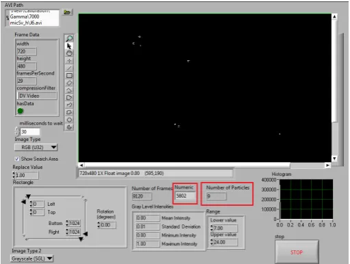
Figure 3: The program designed for this experience
2. Thin plastic filter (50 mg/cm2 plastic thickness density): This filter can only block the passage of low-energy beta rays. Other rays pass through it.
3. Thick plastic filter (thickness density 300mg/cm2): This filter absorbs low-energy X-rays (less than 20keV) and beta low-energy and/or high-energy beams.
4. Aluminum filter: This filter absorbs all beta and X-rays with energy less than 65keV.
5. Tin and lead filter: This filter only passes X-rays with energies greater than 65keV and the film sensitivity under this filter in the energy of 65keV to 2MeV is inde-pendent of X-ray or gamma energy. In this study, we use a digital vision cell that detects the passing rays from the filter. We also need a digital processor to process the information from the image. Then, we will have a sensor that can be used to detect the direction of rays radiation. And we also need an algorithm to read and compute information online. Figure3.
For instance by using mobile camera and the effect of rays on it (1 frame per 30ms) we found that the speed of photography of this camera is higher than the speed of the X-ray.
First solution:
Figure 4: The images achieved from the camera sensor installed on the robot vertical axis
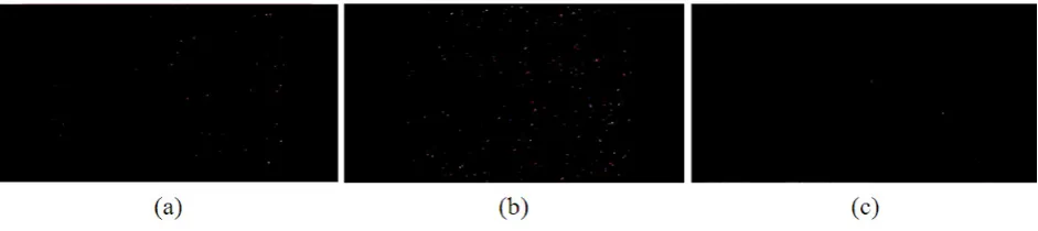
Figure 5: The images achieved from the camera sensor installed parallel to the ground. The light rays that are like white points in the imaging sequences of the video growing in a direction
Now, the robot rotation angle is calculated and the rotation command signal is sent to the wheels. When the robot rotates to the calculated angle direction, the next command would be move in that direction and it would be sent to the wheels. It is possible to scan the environment each time to find the proper direction to the source, and then change the direction of the robot towards the calculated angle and repeat the forward motion sequentially, until, the robot reaches the point that circles around the place. At this time, the center of this circle can be considered as location of the radioactive source.
Second solution:
Place the camera sensor on the robot that is installed parallel to the ground. And start to take pictures. It is expected the rays to enter the image frame from the direction of radiation, and then cover the whole image and eventually exit the frame.
Using the results of this experiment, the robot could find the radiation direction using the imaging sequences. It would find the light rays that are like white points in the imaging sequences of the video growing in a direction. So, if the robot moves in the opposite direction of growing of these points, it can reach the location of the source. Figure5. In Figure 5.a, it is seen that the beams enter the image frame from the top, in the next Figure 5.b the beams cover the entire image and eventually leave from the other side of the image.
Figure 6: Hough transform pseudo-code.
leads to finding the source placement. In this way, it should check the imaging sequences at the right rate, and wherever it could find the light in the form of a comet beams in the image that were growing, The result will indicate that if the robot moves in the opposite direction of these beams growth, it can reach the position of the source.
In this experiment each beam should be calculated separately and then calibrated appro-priately. If the visual sensor (the camera) is overheated, you should use a side cooling system.
In this case, it can even be used on a mobile phone camera. In both proposed methods in this paper, the detection sensor for beam radiation can act as a compass sensor, whose task is to indicate the proper direction of movement to the robot.
Note that the robot is likely to move in an environment with various obstacles. Therefore, at the beginning of the entry into the space, it is necessary to identify the obstacles and the direction of movement in order to see the environment to reach to the source location. Eventually, at the moment when the sensor detects the first signals from the radioactive source, the robot will stop seeing environment and start to move forward in that direction in order to find the location of the source.
In this paper, the robot has been considered as a point robot and it is searching for a fixed source object in convex obstacles environment.
If the obstacles are not convex, we can use approximate methods to change them to circumscribed polygons in the image. [3] This paper assumes that this step has already been done to simplify the problem. So we discuss about the latest steps:
Step One: The robot should find the corners of the convex obstacles. This is accom-plished by using the Hough Algorithm which efficiently estimates the identifying edge points by transform obstacles image from the Cartesian space to polar space. Figure 6 and 7. [6,7,11]
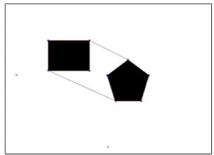
Figure 7: An image of Robot search space and Hough transform Algorithm
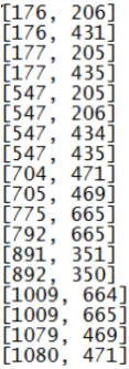
Figure 8: The obstacles corner points coordination of figure 7.a
converting the image to a black and white image and using the edge detection algorithm to find the edges of the obstacles, the Hough transform algorithm should be used, which depicts the lines in the image. Figure 7.b.The image 7.c is obtained by combining the two images 7.a and 7.b. The output of the Hough algorithm could calculate the obstacles corner points. Figure8.
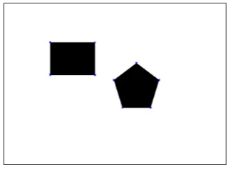
Figure 9: The corner points obtain from Hough transform
in blue. Figure 9.
These points could be considered as important points of image. In this method, we calculate the direction of movement based on the location of these important points.
Step Three: In mathematics, the convex hull of a set of points in the Euclidean space is the smallest convex set containing these points. There are different algorithms which have been presented to calculate this with time complexity of O(nlogn),where n is the number of corner points that we have obtained in the previous step. Figure 10 and11. [2,10]
We continue to calculate the convex hull for points that are enclosed within the previous convex hull. In fact, we calculate the convex layers sequentially, called the onion layer algorithm. Figure12.
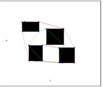
Using the corner points obtained from the previous step and implementing the onion con-vex hull layer algorithm, the processor could determine the robot motion path. Figure13.
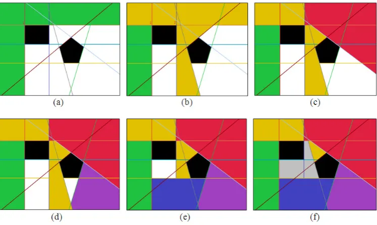
Step Four: We can prove that the robot’s movement on these onion convex hull layers is one of the best options for the robot’s motion to search for a fix object in a convex obstacles space. Proof of this is done by continuing all sides of the obstacles. Figure14. As shown in Fig. 14, the searching space is divided into the convex geometric shapes by continuation of all the sides of the convex obstacles. The robot should search all these convex geometric shapes until it could find the object.
The convex polygonal property is that if the robot is placed at any coordinate of a convex space, it could see all the whole convex area. Therefore, it is necessary for the robot to see only one point of each white convex polygon in the image. So, if the robot sees only one vertexes point which makes larger convex shapes, we could say that all that convex polygon space has been seen. Figure15.
Figure 10: The Convex Hull pseudo-code
Figure 11: The Convex hull of corner points
Figure 13: The onion convex hull layers drown for the obstacles corner points
Figure 14: To proof the method should continue all sides of the obstacles
Figure 16: The onion convex hull layers of estimated obstacles vertices
Figure 17: The Convex Hull pseudo-code
should be less than the number of vertexes. For example, in Figure 15, the total area can be seen with only 6 colors.
Considering that the convex hull is the smallest geometric shape that covers the vertexes, it can be concluded that the proper path for the robot’s motion is the onion convex hull layers of vertexes.
If the robot’s movement path is closed and the robot is not allowed to move, a solution should be proposed for it. Figure 16.
In Figure 16, the onion convex hull layer is plotted for obstacles vertexes consist of three convex hull layers. And some of the sides of the second layer which is plotted in green are drawn into the black obstacles, so that the robot cannot enter these areas.
So, in such a situation it can move as far as it can in the clockwise direction and along the obstacle boundary to the point where it is located. Figure 17.
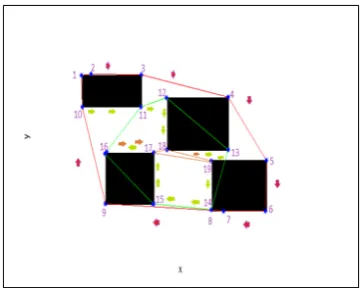
Figure 18: The robot motion path by using the searching algorithm suggested
The angle α can vary according to the accuracy rate and even the size and appearance of the robot and etc. For example, consider the angle α become more, then the accuracy would be less, and vice versa. This angle can be calculated for different types of robots in the lab with trial and error to achieve the desired accuracy.
According to the pseudo-code presented in this article, the path of the robot is shown in the figure below. Figure18.
Figure 18 shows that the robot must first pass the red arrows and so on from point 1 to points 2, 3... 10, respectively. And then enter the second convex hull path showed by green arrows to see points 11, 12..., 16. At the final stage, the orange arrows which mean points 17, 18 and 19 will be visited.
3
Conclusions
This method could be used for intelligent detection and localization of radioactive source. It has been proved that the onion convex hull layers of important points extracted from working environment image would be a proper path for robot movement.
Also, to find the corner points of the convex obstacles, any other algorithm beyond the Hough algorithm could be used. The purpose of the algorithm presented in this paper is to simplify the problem of finding the shortest path and to create a new perspective on solving such problems. Using geometric theorems and definitions, along with image processing techniques, has helped to solve this problem. We look forward to providing a way for more research in this field.
Acknowledgements
References
[1] Auzinger, T., Habel, R., Musilek, A., Hainz, D. and Wimmer M., GeigerCam: Mea-suring Radioactivity with Webcams, SIGGRAPH 2012.
[2] De Berg, M., Cheong, O., Van Kreveld,M. and Overmars, M., Computational Ge-ometry Algorithms and Applications, 2008.
[3] Elyasi, N., Broojerdian, N. and Sorouri Khosroshahi, M., Path planning for teth-ered robot, 48th Annual Iranian Mathematics Conference Bu-Ali Sina University, Hamedan, Iran, 2017.
[4] Ghiyasi-Nejad, M., Katozi M., General courses in radiation protection, Darbid com-pany press, (2009), 5th publish.
[5] Gumiela, M., Kozik, R., Studies of the applicability of CMOS and CCD sensors for detection,dosimetry and imaging of alpha, beta, gamma, X-ray and proton beam spots, The Maria Sklodowska-Curie Secondary School in Andrychw, (2012), AGH University of Science and Technology in Krakw.
[6] Hassanein, A. S., Mohammad, S., Sameer, M. and Ragab, M. E., A survey on Hough Transform, Theory,Techniques and Applications, IJCSI, Vol. 12, Iss. 1 (2015).
[7] Kyewook, L., Application of the Hough Transform, University of Massachusetts, Lowell, January 2006.
[8] ’Radiation burn’ 2017, in Wikipedia: The Free Encyclopedia, Wikimedia Foundation Inc., (2017).
[9] Sharafibadr, A., Gama eye: detector of visible and invisible rays, dosimeter and fire alarm, International Trade Ideas-Inventions-New Products, (2011), Nuremberg Exhibition Center, Germany.
[10] Sharafibadr,A., Nilforoushan,Z., Finding shortest path in the convex obstacles space by using hough transform algorithm and onion convex hulls, 48th Annual Iranian Mathematics Conference Bu-Ali Sina University, Hamedan, Iran, 2017.
![Figure 2: Some of the injuries caused by radioactive source [8]](https://thumb-us.123doks.com/thumbv2/123dok_us/8947381.1856749/3.595.236.365.112.199/figure-injuries-caused-radioactive-source.webp)