0 INTRODUCTION
In arc welding processes, a moving heat source is generally applied for joining plates. The process includes heating as well as cooling of the welded plate whose temperature changes over time and space. Control of the temperature distribution is important for maintaining the quality of the welded plate, which depends on many process parameters (current, voltage, travel speed, etc.). Hence, a detailed study of the distribution of temperature using input process parameters is essential. In the literature, two methods are primarily used for modelling the transient temperature distribution during the welding of plates: numerical [1] to [3] and analytical [4] to [6] methods. In the present work, an analytical solution is used to predict the transient temperature distribution during arc welding of two steel plates.
In the last few decades, many researchers have reported on the transient temperature behavior during welding of plates considering a 2-D heat source. A classical solution for the traisient temperature field is Rosenthal‘s solution [5], which deals with a semi-infinite body subjected to instant point, line, and 2-D surface heat sources. Eagar and Tsai [6] considered a 2-D bell shape for the heat source and predicted the temperature distribution in the heat source region. Jeong and Cho [7] introduced a 2-D Gaussian heat source for determining the temperature field of a finite thick plate. However, the 2-D model of the heat source is unable to predict the penetration effect. Thus, Goldak et al. [1] first introduced a 3-D double ellipsoidal moving heat source for predicting the thermal behaviour during welding. Nguyen et al. [8] presented an analytical solution for the transient temperature field of a semi infinite body subjected to a 3-D dynamic heat source. Winczek [9] described an
analytical solution for the transient temperature field of a semi infinite body caused by a volumetric heat source of Gaussian distribution with different motions. Winczek [10] also provided an analytical solution that considers temperature increments caused by liquid metal and heat radiation of the moving electrode during welding. Li and Lu [11] predicted the temperature distribution considering a hybrid heat source model, the combination of bell shape and ellipsoidal heat sources, during submerged arc welding. The literature shows that mostly ellipsoidal and bell shape heat sources are studied by the researchers. The literature also shows that the shape of the heat source depends on the input process parameters and welding process. Consideration of an oval shape heat source provides an appropriate temperature distribution, particularly in submerged arc welding,. In the present work, therfore, the transient thermal behaviour during submerged arc welding is predicted analytically considering a moving oval heat source. Finally, the analytical prediction is compared with experiments.
1 DESCRIPTION OF THE PHYSICAL PROBLEM
The present work considers the joining of two steel plates (30×15×2 cm) using submerged arc welding. The chemical composition of the steel is described in Table 1. A V-groove of angle 60°was cut on the work pieces along the X-axis. The plates were then firmly fixed to a base plate where a root opening of 0.1 cm was provided to join the plates, keeping the electrode positive and perpendicular to the plates. Fig. 1 shows a schematic of the system where a copper-coated electrode in coil form with a 0.315 cm diameter travels along the X-axis. The electrode is connected to a constant voltage, retifyer type power source with a 1200 A capacity. During welding, a basic fluoride
A Study of Thermal Behaviour during Submerged Arc Welding
Ghosh, A. – Barman, N. – Chattopadhyay, H. – Hloch, S.
Aniruddha Ghosh1,* – Nilkanta Barman2 – Himadri Chattopadhyay2 – Sergej Hloch3 1 Government College of Engineering & Textile Technology, Depertment of Mechanical Engineering, India
2 Jadavpur University, Department of Mechanical Engineering, India
3 Technical University of Košice, Faculty of Manufacturing Technologies, Slovak Republic
The present study reports on thermal behavior during submerged arc welding considering an oval shaped heat source. The welding process is represented by the energy conservation equation where the moving electrode is incorporated considering an oval shaped Gaussian heat source. The governing equation is solved based on the Green function solution and subsequently considered the effect of heat in the weld pool and convection after welding. The prediction agrees well with the experiments and it was found that an oval shape is a better approximation for the heat source.
type granular flux is used. During processing, the temperature at different positions in the welded plate is recorded (as shown in Fig. 1) using two infrared thermometers (OMEGA SCOPE OS524E, 2482 °C, accuracy of 0.2 °C) at positions P1 and P2.
Fig. 1. Schematic of submerged arc welding; the temperature of points (P1 and P2) was recorded
2 MATHEMATICAL MODEL
In the present study, the heat transfer behaviour in the welded plate is representated by the transient heat conduction equation. The corresponding governing equation is given as:
k T q C T
t p
∇ + = ∂
∂
2 ρ , (1)
where T = T(x, y, z, t) is the temperature at a point (x, y, z) at time t and q is a 3-D Gaussian oval heat source. A schematic of the heat source is shown in Fig. 2. During welding, the heat source moves along the x-axis with a constant velocity (v). The heat generated by the heat source at a point (x, y, z) at any instant t is considered to be:
q x y z Ae ax by cz emx
( , , )= −( 2+( 2+ 2)× ),
(2) where A is maximum heat density and a, b, c and m are the heat source parameters. The maximum heat density (A) is found to be:
A abc
em a Q
=2 3 2 × 214 × 0
π / ( /( )) , (3)
where Q0 (Q0 = I × V × ŋ) is the total heat input. V, I and ŋ are the welding voltage, current and arc efficiency, respectively. In the present case, the arc efficiency is considered to be 1 [6].
It was found from the experimental data that the shape of a weld pool is oval on the X-Y plane (z = 0). The corresponding shape of the weld pool, based on the experimenatal data, is shown in Fig. 3. The equation of the oval weld pool was found to be:
x2 y e x
2 2
2 0 3
1 3. 1 13. 1.
.
+ × = (4)
The equation for an oval shape heat source, based on Eq. (2), is considered to be:
ax2+
(
by2+cz2)
×emx 1(
)
= , (5)where a is a semi major axis, b is a semi minor axis, and c is another semi-principal axis of an ellipsoid (ax2 + by2 + cz2 = 1). Hence, in the present work, m is considered to be 0.3. The constants (a, b and c) for the oval shape bead geometry are taken from Goldak and Akhlaghi [12] as:
a L
=ln( ) ,202 (6)
b B
=ln( ) ,202 (7)
and c
C
=ln( ) ,202 (8)
where B, C and L are the half of the bead width, penetration of weld pool, and half of the major axis of oval shape (L ≈ 1.15 B), respectively. B and C were determined experimentally. The corresponding values of B and C are given in Table 2.
Initial and Boundary Conditions
Intially, the heat source is located at:
x = 0 at t = 0 , (9) T(x, y, z, 0) = T0, T(±∞, ±∞, ±∞, t) = T0 (10)
Table 1. Chemical composition of the C-Mn steel work piece [%]
C Sn Mn P S Cr Ni Mo Cu Al
3 TEMPERATURE INCREMENT CAUSED BY HEAT RADIATION OF THE MOVING ELECTRODE
A general solution [5] of the governing Eq. (1) based on the Green function for an instantaneous unit heat source is:
G x x y y z z t t
cp t t e
x x y y
( ', ', ', ')
[ ' ]/
[ ' '
− − − − =
=
−
(
)
−( − )+ −(
1
4 3 2
2
ρ απ
))+ −( ) − ( )
2 2
4
z z t t
'
' ],
α (11)
where α (α = k / ρcp) is the thermal diffusivity and
t' is the electrode travel time. Eq. (11) gives the temperature increment at a point (x, y, z) at an instant t for the unit heat source applied at point (x', y', z') at an instant t'. Due to the linearity of Eq. (11), the temperature variation induced at point (x, y, z) at time t by the instantaneous heat source q (x', y', z', t') applied at (x', y', z') at time t' is:
q(x', y', z', t')G (x–x', y–y', z–z', t–t'). (12) It is assumed that the heat is continuously generated at point (x', y', z') from t' = 0, thus the temperature increment at point (x, y, z) at time t is given as:
q x y z t G x x y y z z t t dt t
( , , , ) (' ' ' ' − ', − ', − ', − ') .
∫
0For an infinite medium, the temperature increment at point (x, y, z) at an instant t is given as:
∆T x y z t q x y z t
G x x y y z z t
( , , , ) ( , , , )
( , ,
=
− − −
× ×
−∝ ∝
−∝ ∝
−∝ ∝
∫
∫
∫
∫
' ' ' '' '
0
'',t t dx dy dz dt'− ') ' ′ . (13) In the present work, the temperature distribution considering an oval shape heat source was found to be:
∆T x y z t Q
C
abc e
t t t
p
m
( , , , ) / /
/
= × ×
× ×
−
(
)
∫
122 1
4 0
0
3 2
2 3 3 2
2 ρ
π
π πα '
//( )4a ,
x y z
I I I dt
× × × ′ (14)
where Ix, Iy and Iz are calculated as Eqs. (15) to (17).
I e e dz
t t t
z
z z
t t cz emx
= ×
− − −
− −∞
∞ −
∫
( ( ( ))) ( )( )
'
' ' '
' =
= '
2
2 4α
πα
44 1
2
4 1
c f x t t e
ce z cf x t t
mx
α
α
( )( ) ,
( ) ( )
' '
'
' '
− + ×
−
− + (15)
I e e dz
t t t
y
y y
t t cy emx
= ×
− − −
− −∞
∞ −
∫
( ( ( ))) ( )( )
'
' ' '
' =
= '
2
2 4α
πα
44 1
2
4 1
b e t tmx e
be y be t t
mx mx
α
α
'
' '
' '
( ) ,
( )
− + ×
−
− + (16) Table 2. The values for the bead parameters (B ,C/P and R)
Voltage [V]
Current [A]
Travel speed (v) [cm/min]
Bead width (B) [mm]
Penetration (C / P) [mm]
Maximum reinforcement height (R) [mm]
35 450 30 22.66 7.78 1.94
Fig. 2. Schematic of an oval heat source during welding with weld
I e e I I dx
t t t
x
x x
t t ax
y z = × × × − − − − −∞ ∞ −
∫
( ( ( ))) ( ) ( ' ' ' ' = = 2 2 4α πα '' ' ' ' ) ( ( ) )( ( ) ) ( (4 1 4 1
2 4
b t t e c t t e
e
mx mx
by e b t t
mx α α α − + − + × × − −)) ( ) ) ( ) ( ( e bz e
c t t e ax
mx
mx mx
e x
t t t
b t +− − + − − × + + −
1 4 1
2 2 4 α πα α ' ' −− + − + × × − − − − + −
t e c t t e
e
mx mx
by e b t t e
mx mx ' ' ' ) )( ( ) ) ( ( )
1 4 1
2 4
α
α 11 4 1
4 4 2 2 2 − − + − − − − × bz e
c t t e ax
x t t
mx mx
e x
α( ') ) α( ') . (17)
As this work considers a moving electrode during welding, the corresponding effect is incorporated in the Ix term as Ixv˝= f (x–vt'). Eq. (18) thus becomes:
∆T x y z t
C t t
abc e t p m a , , , ( ) / / / /(
(
)
= × −[
]
× × ×∫
12 8 11
0 3 2 3 2
3 2 2 4
ρ π πα
π
'
))×Q I0× xv× ×I I dty z '. (18) 4 EFFECT OF MOLTEN METAL
ON THE TEMPERATURE INCREMENT
The present work also considers the effect of molten liquid (weldpool) on the temperature increment. A schematic of a parabolic shaped weldpool is shown in Fig. 4 where a local coordinate is considered at the top of the weldpool. The top surface of the plate is shown by a dotted line in Fig. 4. The weld reinforcement (the part of weldpool above the top surface of plate) is given as:
z R
B y
=42 2, (19)
where R is the maximum reinforcement height. In the case of penetration depth, the equation of the parabola is given as:
z R
B y P R
=42 2+ + , (20) Hence, the total amount of heat delivered by the weldpool is:
Q q dz dy dxv
Ry B Ry B P R B B l l = + + − −
∫
∫
∫
/2/2 //22 44 2//2 ' ' '. 2 2∆ ∆
(21) The temperature increment is given as:
dT q
C t e
e wb v p x x t y y t = × × − − − − ρ πα α α ( )/ ( ) ( )
4 3 2
4 4 2 2 ' ' − −
×e dz dy dx
z z t ( ') ' ' ', 2 4α
where qv is a volumetric heat source at point (x', y', z')
due to the molten weldpool. The corresponding total increment in temperature (ΔTwb) for deposition of the
liquid melt is:
∆T x y z t q
C t
wb v
p Ry B
Ry B P R
B B ( , , , ) ( )/ / / / / = + + × − −
∫
∫
ρ πα4 3 2 4 4 2 2 2 2 2 2 ∆∆ ∆ l l t x x t y y t
e e e
/ / ( ) ( ) 2 2 0 4 4 2 2
∫
∫
× − × × − − − − ' ' α α (( ) , z z tdz dy dx dt − ' ' ' ' 2 4α (22) where, qv is the volumetric heat source rate.
Hence, the total increment in the temperature during welding is given as:
T(x, y, z, t) – T∞ = ΔT(x, y, z, t) + Twb(x, y, z, t), (23)
where T(x, y, z, t) is the variable temperature of the welded plate and T∞ is the initial temperature of plate.
Fig. 4. Geometry of a weldpool
5 CHANGE IN TEMPERATURE DUE TO CONVECTIVE HEAT LOSS
To incoporate the heat loss due to convective heat transfer after welding, the welded plate is divided into a number of cubical segments (10×10×10 mm). It was found that the Biot number (Bi) for each segment is 0.003. Hence, based on the lumped capacitance model, the temperature, T(x, y, z, ti), at time (ti – t) after
welding is given as:
T x y z t T
T x y z t Ti e t ti
( , , , )
( , , , ) ,
( ) −
− ∞∞ =
−τ − (24)
where τ is the time constant (τ = h /(ρLcCp)). Lc is the
a)
b)
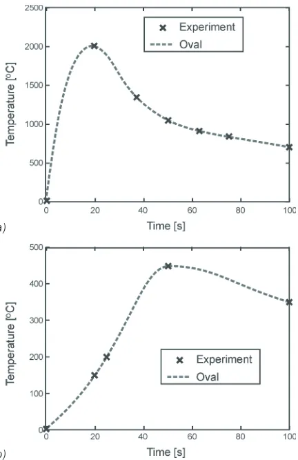
Fig. 5. Variation in temperature with time considering an oval shape heat source at: a) point P1 (2.5 cm, 1 cm, 0) and b) point P2
(2.5 cm, 10 cm, 0 cm)
Fig. 6. Variation in temperature over time for different shape heat sources at point P1 (2.5 cm, 1 cm, 0 cm)
6 RESULTS AND DISCUSSION
The present work predicts the temperature variation during submergerd arc welding based on an analytical solution considering an oval shape Gussian heat
source. Eq. (23) represents the variation in temperature during welding and Eq. (24) represents the variation in temperature after welding. Fig. 5 shows the temperature variation at two different points in the plate over time. The point P1 (2.5 cm, 2 cm, 0) is near the weldpool and the point P2 (2.5 cm, 10 cm, 0) is far from the weldpool. It was found that as the electrode moves toward the points, the temperature of the points increases. Fig. 5a shows that the temperature is very high (~2000 °C) when the electrode comes near to point P1, which is a molten state. On the other hand, the maximum temperature at point P2 is about 475 °C. After welding, the temperature of both the points decreases with time as heat is transferred from the plate surfaces by convection. Subsequently, the predicted temperature is compared with the experimental measurements. A good agreement was found with the experiments.
The present prediction is also compared for different shapes of heat sources. Fig. 6 shows the variation in temperature at point P1 for different shapes of the heat sources. It was found that the prediction considering an oval shape for the heat source provides a better approximation with the experiments.
7 CONCLUSIONS
The present work considers an analytical solution to temperature variation during submerged arc welding considering an oval shaped Gaussian heat source. The solution considers the effect of electrode movement and heat release from the weld pool during welding, as well as convective heat transfer from the plate surface after welding. The present prediction agrees well with the experiments. It was found that the oval shape is a better approximation for the heat source and that taking convective heat loss into account provides good accuracy after welding.
8 NOMENCLATURE
ρ Density [kg/m3]
Cp Heat capacity [W/(kg·K)]
k Thermal conductivity [W/(m·K)] h Convective heat transfer coefficient
[W/(m2·K)] T Temperature [°C] q Heat density [W/m3] t, t', ti Time [s]
Q0 Heat input [W]
I Current [A]
V Voltage [V]
ŋ Arc efficiency
T(x, y, z, t) Temperature of welded plate at (x, y, z) point at time t
L, B, C Weld bead parameters
C/P Penetration
ΔTwb (x, y, z, t) Change of temperature due to
application of oval heat source [°C]
ΔToa (x, y, z, t) Change of temperature due to heat
transfer from molten electrode [°C] 7 REFERENCES
[1] Goldak, J., Chakraborty, A., Bibby, M. (1984). A new finite element model for welding heat sources.
Metallurgical Transactions B, vol. 15, no. 2, p.
299-305, DOI:10.1007/BF02667333.
[2] Gue, M., Goldak, J.A. (1994). Steady-state formulation for stress and distortion of welds. Journal
of Engineering for Industry, vol. 116, p. 467-474,
DOI:10.1115/1.2902130.
[3] Younise, B., Rakin, M., Medjo, B. (2010). Numerical analysis of constraint effect on ductile tearing in strength mismatched welded CCT specimens using micromechanical approach. Tehnički vjesnik - Technical
Gazette, vol. 17, no. 4, p. 411-418.
[4] Ghosh, A., Chattopadhyaya, S., Hloch, S. (2012). Prediction of weld bead parameters, transient temperature distribution & HAZ width of submerged
arc welded structural steel plates. Tehnicki Vjesnik -
Technical Gazette, vol. 19, no. 3, p. 617-620.
[5] Fachinotti, V.D., Cardona, A. (2008). Semi-analytical solution of the thermal field induced by a moving double-ellipsoidal welding heat source in a semi-infinite body. Mecanica Computacional, vol. 27, p. 1519-1530.
[6] Eager, T.W., Tsai, N.S. (1983). Temperature fields produced by traveling distributed heat sources. Welding
Journal, vol. 62, no. 12, p. 346-355.
[7] Jeong, S.K., Cho, H.S. (1997). An analytical solution to predict the transient temperature distribution in fillet arc welds, Welding Journal, vol. 76, no. 6, p. 223-232. [8] Nguyen, N.T., Ohta, A., Suzuki, N., Maeda, Y. (1999).
Analytical solutions for transient temperature of semi-infinite body subjected to 3-D moving heat source.
Welding Journal, p. 265- 274.
[9] Winczek, J. (2010). Analytical solution to transient temperature field in a half infinite body caused by moving volumetric heat source. International
Journal of Heat Mass Transfer, vol. 53, p. 5774-5781,
DOI:10.1016/j.ijheatmasstransfer.2010.07.065.
[10] Winczek, J. (2011). A new approach to modelling of temperature field in surface steel elements.
International Journal of Heat and Mass Transfer,
vol. 54, no. 13, p. 4702-4709, DOI:10.1016/j. ijheatmasstransfer.2011.06.007.
[11] Li, P., Lu, H. (2012). Hybrid heat source model designing and parameter prediction on tandem submerged arc welding. International Journal of
Advanced Manufacturing Technology, vol. 62, Issue
5-8, p. 577-585, DOI:10.1007/s00170-011-3829-x. [12] Goldak, J.A., Akhlaghi, M. (2005). Computational
Welding Mechanics. Springer, New York,NY 10013,
![Table 1. Chemical composition of the C-Mn steel work piece [%]](https://thumb-us.123doks.com/thumbv2/123dok_us/8951217.1860585/2.586.375.506.460.547/table-chemical-composition-c-mn-steel-work-piece.webp)