International Journal of Science Technology
Management and Research
Available online at: www.ijstmr.com
IJSTMR
©
2017 | All Rights Reserved 33Enhancement of Power Quality using Power
Electronics Transformer based DVR
Mr. Kiran P. Varade
PG,Scholar (Electrical Power system)S.N.D COE & Research Center Yeola, Nashik, MH [email protected]
Prof. P. C. Tapare
PG Guide & Head of Electrical Engineering Dept. S.N.D COE & Research Center
Yeola, Nashik, MH [email protected]
Prof. C. Veeresh
PG Coordinator of Electrical Engineering Dept. S.N.D COE & Research Center
Yeola, Nashik, MH [email protected]
Abstract: In this paper a three phases four wire dynamic voltage restorer (DVR) with bidirectional power electronic
transformer structure is proposed to inject required compensating series voltage to the electronic power system in such a way that continuous sinusoidal voltage is seen at load side ever at heavy fault occurrences at utility side .the proposed structure is composed of three-phase four leg inverter, three single-phase high frequency transformer , three cycloconverters and high frequency harmonic filter that are connected to the utility. Three dimensional space vector modulation (3DSVM) methods are used for pulse generation. Fourth added wire enables the DVR to compensate unbalance voltage disturbance that are custom power problems in electrical utility. The performance of the structure and applied switching scheme are verified under both balanced and applied switching scheme are verified under both balanced and unbalanced disturbances via simulation study in MATLAB software.
Keywords: PET, DVR; 3DSVM; Power quality;
I. INTRODUCTION
Power quality (PQ) problems have obtained increasing attentions as they can affect lots of sensitive end-users including industrial and commercial electrical consumers. Studies indicate that voltage sags, transients, and momentary interruptions constitute 92% of all the PQ problems occurring in the distribution power system. In fact, voltage sags have always been a huge threat to the industry, and even 0.25s voltage sag is long enough to interrupt a manufacture process resulting in enormous financial losses. Voltage sags are generally classified according to its depth and duration time. Typical sag can be a drop to between 10% and 90% of the rated RMS voltage and has the duration time of 0.5 cycles to 1 min. According to the data presented in majority of the sags recorded are of depth no less than 50% but deeper sags with long duration time obviously cannot be ignored as they are more intolerable than shallow and short-duration sags to the sensitive electrical consumers.
IJSTMR
©
2017 | All Rights Reserved 34 Based on the aforementioned discussions, this paper proposes a PET based three-phase four-wire DVR to inject required compensating series voltage to the power system in such a way that continuous sinusoidal voltage is seen at load side ever at heavy fault occurrences at utility side. The proposed structure is composed of a three-phase four-leg inverter, three single-phase high frequency transformers and a three-phase high frequency harmonic filter that are connected to the utility.
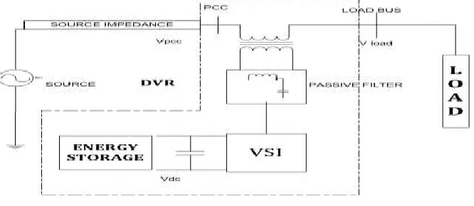
Fig.1 Basic Structure of A DVR
II. METHODOLOGY
In this paper a three phases four wire dynamic voltage restorer (DVR) with bidirectional power electronic transformer structure is proposed to inject required compensating series voltage to the electronic power system in such a way that continuous sinusoidal voltage is seen at load side ever at heavy fault occurrences at utility side .the proposed structure is composed of three-phase four leg inverter, three single-phase high frequency transformer , three cyclo converters and high frequency harmonic filter that are connected to the utility. Three dimensional space vector modulation (3DSVM) methods are used for pulse generation. Fourth added wire enables the DVR to compensate unbalance voltage disturbance that are custom power problems in electrical utility. The performance of the structure and applied switching scheme are verified under both balanced and applied switching scheme are verified under both balanced and unbalanced disturbances via simulation study in MATLAB software. Dynamic voltage restorer (DVR) can provide the lucrative solution to mitigate voltage sag by establishing the appropriate voltage quality level, necessary. It is recently being used as the active solution for mitigation of power quality problems.
Fig. 2. Control block diagram of DVR
IJSTMR
©
2017 | All Rights Reserved 35voltage THD, less switching and conduction losses, wide linear modulation range, more output voltage magnitude and its simple digital implementation [l2]. The block diagram of the control system used is shown in Fig. 2.
III. SIMULATION&RESULTS
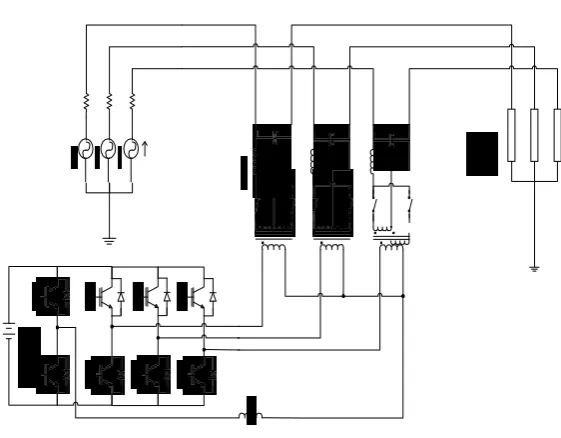
Fig. 3. Three-Phase Four-Wire DVR
In this section, the proposed system in Fig.l is simulated in MATLAB. System parameters are given Table 1. It should be noted that the series transformers are operating at switching frequency and in linear region. Fig. 8 shows the simulation results under balance voltage sag condition. In this case, 50% voltage sag has been considered for each phases. Utility voltage, injected voltage and load voltage are shown, respectively. It is clear that the load voltage is restored to the nominal condition (before sag occurrence) after a time lower than a half cycle. It shows the simulation results under unbalance voltage sag condition with the values of 60%, 50% and 40% on phases a, b, and c, respectively. As can be seen, under such conditions, this structure injects unbalance voltage in such a way that the load voltage remains balanced and sinusoidal and doesn’t sense the voltage sag.
TABLE I. System parameters
Parameters Value
Line Frequency 50Hz
Switching frequency l0000Hz
Load voltage 230vrms
dc bus voltage 80v
Series transformer turns ratio l:4
Filter inductance and capacitance lmh & 25f
IJSTMR
©
2017 | All Rights Reserved 36Fig.4. Simulation results under balanced sag (a) utility voltages (b) injected voltages (c) load voltages
IJSTMR
©
2017 | All Rights Reserved 37Fig.6. Simulation results under harmonic polluted utility voltage (a) utility voltages (b) injected voltages (c) load voltages
The THD values of utility voltages and load voltages compensated are given in TABLE. The THD of the load voltage is less than 3% that lays in the criterion reported in IEEE standards 5l9-l992.
TABLE II. THDs of utility and load voltages
THDa THDb THDc
Utility Voltage %38.87 %32.02 %4l.66
Load Voltage %2.28 %l.9l %2.37
CONCLUSION
In this paper, a three-phase four-wire DVR is presented to compensate the balanced and unbalanced sag and swell voltage using three dimensional space vector modulations. The performance of DVR is validated through simulations in MATLAB and the results verify the analysis. According to the results, DVR injects appropriated series voltage during utility voltage disturbance and maintains the load voltage at desired value. Also the THD values of the load voltage are less than the standard values.
REFERENCE
1. Aziz Tashackori, Seyyed Hossein Hosseini, Mehran Sabahi, “Power Quality Improvement using a power electronic transformer based DVR” in 2015 23rd Iranian Conference on Electrical Engineering (ICEE).
2. M. Gyugyi et al., “Apparatus and method for dynamic voltage restoration of utility distribution networks,” U. S. Patent 5 329 222, July l2, l994.
3. G. T. Heydt, W. Tan, T. LaRose, and M. Negley, “Simulation and analysis of series voltage boost technology for power quality enhancement,” IEEE Trans. Power Del., vol. l3, no. 4, pp. l335–l34l, Oct. l998.
4. J. G. Nielsen, M. Newman, H. Nielsen, and F. Blaabjerg, “Control and testing of a dynamic voltage restorer (DVR) at medium voltage level,” IEEE Trans. Power Electron., vol. l9, no. 3, pp. 806–8l3, May 2004.
5. A. Tashackori, S.H Hosseini, M. Sabahi, T. Nouri, “A three-phase four- leg DVR using three dimensional space vector modulation,” Electrical Engineering (ICEE), 20l3 2lst Iranian Conference on, vol., no., pp.l,5, l4-l6 May 20l3.
6. M.D. Manjrekar, R. Kieferndorf, G. Venkataramanan, “Power electronic transformers for utility applications,” IEEE Conference Record, Industry Applications Conf., Oct. 2000, Vol.4, pp. 2496-2502.
7. J. Aijuan, L. Hangtian, L. Shaolong, “A New High-Frequency AC Link Three-Phase Four-Wire Power Electronic Transformer,” IEEE Conf. on Indus. Electronics and Applications, May 2006, pp. l-6.
8. M. Sabahi, A.Y. Goharrizi, S.H. Hosseini, M.B.B Sharifian, G.B. Gharehpetian, “Flexible Power Electronic Transformer,” Power Electronics, IEEE Transactions on , vol.25, no.8, pp.2l59,2l69, Aug. 20l0.
9. H. Krishnaswami, V. Ramanarayanan, “Control of High-Frequency AC Link Electronic Transformer”, IEE Proc. Elect. Power Appl., May 2005, Vol. l52, No. 3, pp. 509-5l6.
10. S.H. Hosseini, M.B.B. Sharifian, M. Sabahi, A.Y. Goharrizi, G.B. Gharehpetian, ‘Bi-directional power electronic transformer based compact dynamic voltage restorer,’ Power & Energy Society General Meeting, 2009. PES '09. IEEE , vol., no., pp.l,5, 26-30 July 2009.
11. Changjiang Zhan, Atputharajah Arulampalam and Nicholas Jenkins, “Four-wire Dynamic Voltage Restorer based on a three-dimensional voltage space vector PWM algorithm,” IEEE Trans. on Power Electronics, Vol. l8, No. 4, pp. l093-ll02, July. 2003.
12. A. Gosh and Gerard Ledwich, “Compensation of distribution system voltage using DVR,” IEEE Trans. on Power Delivery, vol. l7, no. 4, pp. l030-l036, Oct. 2002.