T E C H N I C A L N O T E
Open Access
Analysis of intensity and sensitivity of single- and
multiple-channel RF head coils in 3.0-T MRI system
Junyong Park
*, Janggeun Cho and Chulhyun Lee
Abstract
Background:High-resolution anatomical and functional images can be acquired using high- and ultrahigh-field
magnetic resonance imaging (MRI) systems. An increase in the main magnetic field strength results in high resolution but suffers from the disadvantage of field nonuniformity in the radio frequency (RF). To overcome this RF field inhomogeneity, parallel RF transmission system and sensitivity encoding are widely used.
Findings:Our experimental results showed that the best signal intensity was in transmit and receive mode head
coil, except for the T2-weighted fast field echo (FFE). The best signal-to-noise ratio (SNR) was in the 32-channel head coil.
Conclusion:In general, multiple-channel coils have been known as more efficient materials in terms of SNR. However, they may not be as important in experiments where intensity is an important factor. Therefore, a suitable coil should be selected using a pulse sequence.
Keywords:SNR; Slice profile; Coil; Pulse sequence
Findings Introduction
In clinical and research fields, 3.0-T magnetic resonance imaging (MRI) systems have been widely used. Increas-ing the main magnetic field strength (≧3.0 T) offers the advantage of high resolution but results in the disadvan-tage of nonuniformity in the radio frequency (RF) field because of the short RF wave length (Hoult and Phil 2000). To exploit the inherent advantages and to over-come the challenges of using high-field scanners for the MRI, dedicated RF coils such as multi-channel RF (Adriany et al. 2010), sensitivity encoding (Pruessmann et al. 1999), transverse electromagnetic (Vaughan et al. 1994), and micro-strip transmission line volume coils (Zhang et al. 2001) have been developed.
In the present study, four RF head coils [transmit and receive mode (T/R) head coil and 8-, 16-, and 32-channel head coils] were evaluated and compared in a 3.0-T MRI system. The commercial RF head coils were provided by Philips Medical System (Cleveland, OH, USA). Except for the T/R head coil, the multi-channel RF coils operated in the Rx mode only. For high-quality
image acquisition, an MRI user had to adaptively select the RF coil according to a given RF pulse sequence. Each RF coil performance was evaluated and compared in terms of signal-to-noise ratio (SNR), slice profile, and RF field uniformity.
As a result, a parallel RF transmission system and an increased number of RF coil channels can improve the SNR. However, the T/R head coil has the highest signal intensity with a high noise level. An MRI user must adaptively select the RF coil for the image using the RF coil evaluation results in this study.
Availability and requirements Methods
The purpose of this study is to evaluate the T/R head coil and the 8-, 16-, and 32-channel head coils using each RF pulse sequence [T1-weighted spin echo (SE), T1-weighted fast field echo (FFE), T2-weighted turbo SE (TSE), and T2-weighted FFE] in terms of SNR, slice pro-file of the images, and RF field uniformity. The image positions were at the center and edge (slice offset, 40 mm) slices of the water phantom. These evaluation and comparison studies were conducted on a Philips Achieva 3.0-T MRI system (at the Korea Basic Science
* Correspondence:[email protected]
Division of Magnetic Resonance Research, Korea Basic Science Institute, 804-1 Ochang, Chungbuk 363-883, Republic of Korea
Figure 1SE and FE pulse sequence diagrams.Left, SE; right, FE.
Institute, Ochang, Republic of Korea) using a uniform phantom provided by Philips Medical System.
MR pulse sequence
Two types of magnetic resonance (MR) pulse sequences were tested: the SE RF pulse sequence and the FE RF pulse sequence which is the same as the gradient echo.
Figure 1 shows the basic MR pulse sequences of the SE and FE.
Experimental conditions
The images were acquired by the Philips Achieva 3.0-T MRI system. The T/R head coil was operated in the Tx/Rx mode in the quadrature transmission mode, and the other multi-channel coils used the Rx mode only. Two images (center and edge slices with a 40-mm gap in the water phantom) were acquired per type of pulse sequence.
The parameters for the T1-weighted images with the SE pulse sequence are echo time (TE)/repetition time (TR) = 10/500 ms, field of view (FOV) = 240 × 240 mm2, recon matrix size = 560 × 560, slice thickness = 5 mm, and flip angle = 90°.
The parameters for the T2-weighted images with the SE pulse sequence are TE/TR = 80/3,000 ms, FOV = 240 × 240 mm2, recon matrix size = 560 × 560, slice thickness = 5 mm, flip angle = 90°, refocusing angle = 120° (refocusing control), and TSE factor = 15.
The parameters for the T1-weighted images with the FFE pulse sequence are TE/TR = 4.60414696 (in-phase)/ 250 ms, FOV = 240 × 240 mm2, recon matrix size = 560 × 560, slice thickness = 5 mm, and flip angle = 80°.
The parameters for the T2-weighted images with the FFE pulse sequence are TE/TR = 16.1145134
(in-phase)/685 ms, FOV = 240 × 240 mm2, recon
matrix size = 560 × 560, slice thickness = 5 mm, and flip angle = 18°.
The MR images were acquired using a water phan-tom (16-cm-diameter refill bottle provided by Philips Medical System). Four RF coils were evaluated using the four types of sequences (SE and FE with T1 and T2 weighting).
All experiments were performed under the same condition. The signal-scale ranges were set to be the same prior to the image acquisition. After the image acquisition, the contrast and signal-scale ranges were set to be the same using MATLAB (Mathworks, Natick, MA, USA).
Results
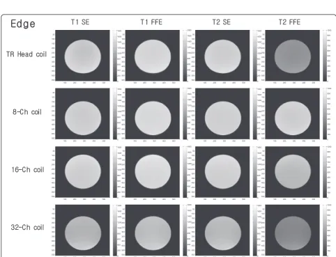
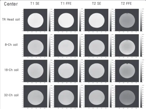
The digital imaging and communications in medicine (DICOM) images of the edge and center slices are shown in Figures 2 and 3, respectively. They were set at the same signal scale and contrast ranges. From the re-sults, the T/R head coil shows maximum image signal intensity level in all sequence parameters except for the T2-weighted FFE.
Increasing the RF coil elements resulted in the de-crease in the signal intensity. On the other hand, the 32-channel head coil has the highest SNR and the lowest noise level, as shown in Figures 4 and 5.
Additionally, we confirmed that the T/R head coil has the highest signal intensity, and the multi-channel
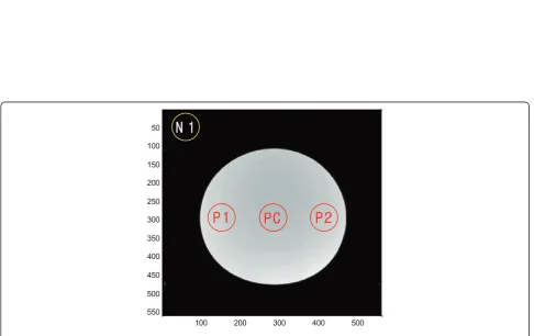
RF coils have a high SNR. Figure 6 shows the positions of each image where the signal intensity, noise (three-point center slice), and SNR were calculated.
Conclusions
With the exception of the T2-weighted FFE, the T/R head coil has the advantage in terms of signal intensity. On the other hand, the 32-channel head coil shows the best performance in terms of SNR.
In the T2-weighted FFE imaging, we can use an 8-channel head coil for the signal intensity and a 32-channel head coil for SNR.
For the other weighted images, a T/R head coil can be selected for the signal intensity, and a 32-channel head coil can be selected for SNR.
In general, multiple-channel coils have been known to be more efficient materials in terms of SNR.
However, they may not be as important experiments where the signal intensity is an important factor. There-fore, a suitable coil should be selected using the pulse sequence.
In other words, the coil that must be used in experi-ments that require high intensity (such as fMRI) and a signal from a phantom or a coil in terms of its purpose (such as SNR and CNR) in the anatomical image should be selected carefully.
Figure 5Slice signal intensity profile of the edge slice images.
Competing interests
The authors declare that they have no competing interests.
Authors’contributions
JP designed experiments and wrote the manuscript. JC analyzed the data and CL supervised the study. All authors read and approved the final manuscript.
Received: 12 August 2013 Accepted: 4 December 2013
References
Adriany G, Auerbach EJ, Snyder CJ, Gözübüyük A, Moeller S, Ritter J, Van de Moortele PF, Vaughan T, Uğurbil K (2010) A 32-channel lattice transmission line array for parallel transmit and receive MRI at 7 tesla. Magn Reson Med 63(6):1478–1485
Hoult DI, Phil D (2000) Sensitivity and power deposition in a high-field imaging experiment. J Magn Reson Imaging 12(1):46–67
Pruessmann KP, Weiger M, Scheidegger MB, Boesiger P (1999) SENSE: sensitivity encoding for fast MRI. Magn Reson Med 42: 952–962
Vaughan JT, Hetherington HP, Otu JO, Pan JW, Pohost GM (1994) High frequency volume coils for clinical NMR imaging and spectroscopy. Magn Reson Med 32(2):206–218
Zhang X, Ugurbil K, Chen W (2001) Microstrip RF surface coil design for extremely high-field MRI and spectroscopy. Magn Reson Med 46(3):443–450
doi:10.1186/s40543-014-0025-2
Cite this article as:Parket al.:Analysis of intensity and sensitivity of single-and multiple-channel RF head coils in 3.0-T MRI system.Journal of Analytical
Science and Technology2014 :25.
Submit your manuscript to a
journal and benefi t from:
7Convenient online submission 7Rigorous peer review
7Immediate publication on acceptance 7Open access: articles freely available online 7High visibility within the fi eld
7Retaining the copyright to your article