http: // www.ijrtsm.com© International Journal of Recent Technology Science & Management 56
ISSN : 2455-9679
[Nitin al. , 4(1), Jan 2019] Impact Factor : 2.865
IJRTSM
INTERNATIONAL JOURNAL OF RECENT TECHNOLOGY SCIENCE & MANAGEMENT
“
NEW DESIGN DEVELOPMENT OF CIRCULAR RING SPECIMENS FOR FRICTIONDETERMINATION IN METAL FORMING PROCESS BY USING ANSYS SOFTWARE
”
Nitin Jain
1,
Dr. P.K. Sharma
21M.Tech Scholar, Dept. of Mechanical Engineering,
NIIST
Bhopal, MP, India 2Associate Professor, Dept. of Mechanical Engineering,NIIST
Bhopal, MP, India
ABSTRACT
The main objective of this research is to find alternate specimen for friction determination, and develop their friction calibration curve. Finite Element simulation is carried out using these alternative specimens and friction calibration curves are generated. Result of these curves is compared with ring compression test. The result of this investigation shows that such alternative specimens may play important role in friction determination in absence of ring specimen. It is observed that the geometry of those specimens which consist any geometrical shape inside circle give very close friction values. CAD geometry object made on Autodesk Inventor Ver 2016 and simulation has done on ANSYS VER 17.0
Keyword: Friction Coefficient, Metal Forming Process, Ring Compression Test, Finite Element, CAD, ANSYS
I. INTRODUCTION
Friction is defined as the resistance to the relative sliding between two bodies in contact under a normal load. Metal working and manufacturing process are significantly affected by friction, because of the relative motion and the force present between tool dies, and work pieces. Friction has significant effects on both the work pieces and process variables such as deformation load, metal flow, surface quality and internal structure of the product in metal forming processes. Therefore, the interface friction has to be understood and control. For effective friction control, effects of the deformation process variables, such as deformation speed, material type, and lubrication, must be treated together to investigate interaction effects among these variables. There are several methods developed for quantitative evolution of friction at the die/work piece interface in metal forming process. The most accepted one is to define a coefficient of friction, μ, the coulomb law of friction expressed as
τ = μ.p
where, τ is the frictional shear stress and p is the normal stress.
http: // www.ijrtsm.com© International Journal of Recent Technology Science & Management 57
ISSN : 2455-9679
[Nitin al. , 4(1), Jan 2019] Impact Factor : 2.865
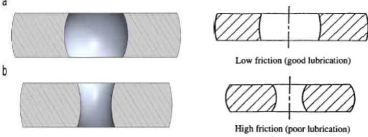
coefficient at the die/ work piece interface. If the specimen‟s internal diameter increases during the deformation, friction is low; if the specimen’s internal diameter decreases during the deformation, the friction is high
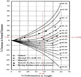
Using this relationship, specific curves, later called friction calibration curves, were generated by Male and Cockcroft relating the percentage reduction in the internal diameter of the test specimen to its reduction in height for varying degrees of the coefficient of friction as shown in Graph 1.
Fig. 1 Effect of friction magnitude on metal flow during the ring compression test
Male and Cockcroft‟s standard ring geometry of 6:3:2 was used, and calibration curves are formed to ring geometries. Each ring geometry; has its own specific set of curves. The most common ring geometry is 6:3:2 where the first number denotes the outer diameter; and the second number denotes the internal diameter while the last one is for height of the ring. Lee developed a method to find the friction factor of the die/work piece interface for the forging process without the need for measurement of the shape changes of the work piece. Using the proposed model to predict the influence of die velocity on the friction factor showed that the friction factor decreases when the die velocity was increased. Bugini developed FEM calibration chart for ring upsetting at room temperature when dealing with annealed Aluminum specimens of different height. The method allows the evolution of the friction coefficient affecting the plastic flow when Teflon films are interposed between dies and specimens. Hayhurst proposed a new technique of calibration, which utilizes two test piece geometries, namely the solid cylindrical compression test piece and the ring compression test piece. It has been shown that it is possible to derive the true stress-true stain curve for the work piece materials; and, to calibrate the friction model. The geometrical changes of all test pieces carefully measured throughout the tests, for a range of four different friction conditions, dry friction, lubricant, lead metal and nylon, have been predicted with good accuracy using the true stress-true strain constitutive models; the two parameter friction model, and the finite-element analysis procedures. Sofuoglu and Rasty address the dependency of the friction calibration curves obtained for the coefficient of friction, μ, on such factors as material properties, strain-rate sensitivity, and barreling.
http: // www.ijrtsm.com© International Journal of Recent Technology Science & Management 58
ISSN : 2455-9679
[Nitin al. , 4(1), Jan 2019] Impact Factor : 2.865
Black and white plasticine as soft (nonmetallic) modeling materials and aluminum, copper, bronze and brass as metallic materials were used to conduct a number of ring compression tests. The necessary material parameters of plasticine for the finite element analysis were obtained from a series of the compression tests. The elastic-plastic finite element code ABAQUS was then used to simulate the ring compression test in order to investigate the effect of the above factors on the friction calibration curves, for Aluminum material as shown in Graph.2 It is observed that very few attempts have been made to generate friction calibration curve using other geometrical shape specimens. Detailed study on how the friction calibration on specimens behave during deformation and what type of deformation take place on the FE deformed mesh has not been conducted.
II. EXPERIMENTAL PROCEDURE
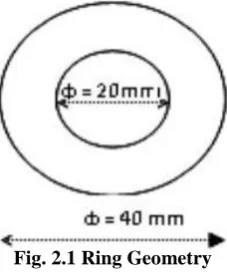
In ring compression test, the geometry of ring specimen has proportion of outer diameter to inner diameter to height (OD : ID: Thickness) of 6 : 3 : 2.In this study of friction calibration curve by ring compression test using three specimens developed:
(1) The name of first specimen is circle in circle i.e. ring, the geometry of ring specimen has proportion of
(2) OD : ID : Thickness. Dimensions of the specimen are 40 : 20 : 13.33.
(3) All dimensions in mm as shown in Fig.2.1
Fig. 2.1 Ring Geometry
Compression test on the specimens are carried out using UTM, All the specimens are comp- ressed between 30% to 45%. Percentage of compression and load applied on the specimens are shown in Table.2.1
Table.2.1 % of Compression and Load requirement on the specimen
III. SIMULATION & MODELING
Finite element analyses of the compression test are carried out in order to study the deformation behavior with respect to friction. FE simulation is carried out using ANSYS [7] software. The interaction of platen and specimen is accounted using CONTACT command, in built in the software. The number of elements and nodes in each model are given in Table.2. FE models are shown in Fig. 2.3(a)-2.3(b)
Table.2.2 FE Parameters for all Specimens
S.No Specimens Load Applied % of
(KN) Compression
1.
Circle in Circle
205 38.85
(Ring )
S.No Specimen No. of
Elements
No. of Nodes
http: // www.ijrtsm.com© International Journal of Recent Technology Science & Management 59
ISSN : 2455-9679
[Nitin al. , 4(1), Jan 2019] Impact Factor : 2.865
Fig. 2.5 Compression Test on copper ring with fix support
Fig. 2.6 Compression Test on copper ring with Force applied
Fig. 2.7 Compression Test on copper ring with all boundary condition
Fig. 2.8 Compression Test on copper ring with Maximum Shear stress
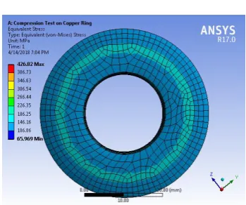
Fig. 2.9 Compression Test on copper ring with Equivalent stress
Fig. 2.10 Compression Test on copper ring with Factor of safety
Fig. 2.3 (a) Specimen before and after compression Fig. 2.4 (b) FE model before and after compression
http: // www.ijrtsm.com© International Journal of Recent Technology Science & Management 60
ISSN : 2455-9679
[Nitin al. , 4(1), Jan 2019] Impact Factor : 2.865
IV. RESULT & DISCUSSION
Values of coefficient of friction, nodal travel for different specimens and stress developed are given in Table.4.1 Using the experimental results and calibration curves, friction is determined for different type of specimens. There are given in Table.4 and compared to ring test results.
4.1 RESULTS
Nodal travel for different specimens and load requirement are given in Table 8.1
Table 4.1 The Coefficient of friction (coulomb) values by FE Simulation.
4.1.1 CALCULATION FOR COEFFICIENT OF FRICTION (Μ) FOR RING.
For Circle (Ring):
Inner diameter of ring before compression = 20 mm
Inner diameter of ring after compression = 18.55 mm ( 18.55 mm This value calculated with help of verniers calipers) % Change in inner diameter = [(20-18.55) / 20]*100 = 7.25 %
% Change in height = [(14-8.56) / 14]*100 = 38.85% ( 8.56 mm This value calculated with help of verniers calipers)
Fig 4.1 Friction calibration curves obtained from the ring compression test for copper in term of μ.
S.No Specimens
Load
Applied
(KN)
% of
Compression
Coefficient of
Friction (μ)
http: // www.ijrtsm.com© International Journal of Recent Technology Science & Management 61
ISSN : 2455-9679
[Nitin al. , 4(1), Jan 2019] Impact Factor : 2.865
Fig 4.2 Ring specimen 2D and Actual model Value of Coefficient of Friction (μ) is 0.076 for Ring are measured by the above figure
4.2 ANALYTICAL CALCULATION:
For Coefficient of Friction (μ) for Ring. For Circle (Ring):
Outer diameter (do) = 40 mm
Inner diameter (di) = 20 mm Thickness (t) = 14mm
Area of outer circle: П/4 *do2 = 1256 mm2
Area of inner circle : П/4 *d12 = 314.28 mm2
A = AO – Ai = 1256 – 314.28 = 941.72mm
2
Ϭ = F/A
Stress = F/A = 205000/941.72 = 217.68 MPa
Now
Shear stress = Tangential force / Area = 205000/ П d t = 205000/ 3.14*20*14 =205000/879.2 = 233.17MPa
Shear Stress = 233.1 MPa
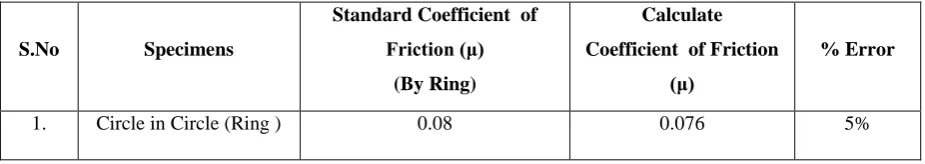
Using the experimental results and calibration curve friction is determined for different type of specimens. These are given in Table 8.2 and compared to ring test results.
Table 4.2 Comparison of Results
S.No Specimens
Standard Coefficient of
Friction (μ)
(By Ring)
Calculate
Coefficient of Friction
(μ)
% Error
1. Circle in Circle (Ring ) 0.08 0.076 5%
V. CONCLUSION
In this research work, We have been made to find alternative specimens for friction calibration using finite element simulation. One specimen is ring and experimental work and FE Simulation on these above specimens are carried out. A ring of standard dimension is also tested in the same machine. We have validated our result of ring specimen with simulation software ANSYS VER 17.0, it is observed that the geometry of specimens which consist any geometry shape inside circle gave very close friction value. Hence, friction prediction become quite simple uses such specimens, especially in the absence of ring specimens.
REFERENCES
1 G.E.Dieter, “Mechanical Metallurgy”, Mcgraw-Hil1, Inc.,bostan,Ma,1986, P 539-549.
2 G.E.Dieter, “Workability Tests, Metals Handbook” volume 14. Forming And Forging, ASM International,
Materials Park,OH,1988, P 379-381.
3 Wang.W, Wagoner.R.H., and Wang X.J., “Measurement Of Friction Under Sheet Forming Conditions”, 27A,
http: // www.ijrtsm.com© International Journal of Recent Technology Science & Management 62
ISSN : 2455-9679
[Nitin al. , 4(1), Jan 2019] Impact Factor : 2.865
4 Sofuoglu Hasan, Assistant Professor, Jahan Rasty, Associate Professor, On The “Determination Of Friction
Coefficient Utilizing The Ring Compression Test”, Journal Of Engineering Materials And Technology, 2001, P 338-348.
5 Sofuoglu H., Gedikli H., “Determination of Friction Coefficient Encountered In Large Deformation Processes”,
Triblolgy International, Vol. 35, 2002, P 27-34.
6 Shivprasad P.V. And Daves C.H.J., “An Assessment Of The Interface Friction Factor Using The Geometry Of
Upset Specimen”, Modelling And Simulation In Material Science And Engg., Vol. 13, 2005, P 355-360.
7 Sahin Mumin, Cem S.C., Etinarslan, Akata H. Erol, “Effect Of Surface Roughness On Friction Coefficients During
Upsetting Processes For Different Materials”, Materials And Design, Vol. 28(2), 2007, P 633-640.
8 Rudkins N.T., Hartley P., Pillinger L.A., Petty D.B., “Friction Modelling And Experimental Observation In Hot
Ring Compression Tests”, Journal Of Materials Processing Technology, Vol. 60, 1996, P 349-353.
9 Robinson T., H. Ou, C.G. Armstrong, “Study On Ring Compression Test Using Physical Modelling And FE
Simulation”, Journal Of Materials Processing Technology Vol. 18, 2004, P 54-59.
10 Rao K.P. And Sivaram K., “A Review Of ring Compression Testing And Applicability Of The Calibration
Curves”, Jouranl Of Materials Processing Technology, Vol. 37, 2008, P 295-318.
11 Meyers M.A., Chawla K.K., “Mechnical Behaviour Of materials, The Fundamentals Of Elastic”, Second Edition,
(Prentice-Hall,1999).
12 Lee Chorng-Der, Cheng I Weng And Jee Gong Chang, “A Prediction Of The Friction Factor For The Forging