Journal on Today’s Ideas – Tomorrow’s Technologies, Vol. 3, No. 1, June 2015 pp. 83–93
DOI: 10.15415/jotitt.2015.31006
A Comprehensive Review of Modulation
Techniques used in Long Term Evolution
SuNITa KumarI aND T. L. SINgaL
Chitkara university, Punjab, India
E-mail: [email protected]
received: December 18, 2014| revised: February 24, 2015| accepted: may 20, 2015
Published Online: June 29, 2015
The author(s) 2015. This article is published with open access at www.chitkara.edu.in/ publications
Abstract: 3rd generation Partnership Project (3gPP) has come up with a
technology called Long Term Evolution (LTE) to attain a new high speed radio access in the field of mobile communications. Design of wireless communication system has been an important and challenging problem due to the nature of wireless channel. There are number of factors involved in the performance of a LTE system. Orthogonal Frequency Division multiple access (OFDma) and Single Carrier Frequency Division multiple access (SC-FDma) are a dominant part of future mobile communication. This paper describes about LTE physical layer, OFDma and SC-FDma receiver and transmitter structures, draw attention on the factor that influences the performance and improvement of multiple access techniques. The substantial use of the adaptive modulation in LTE is the main highlight of the paper. The selection of modulation techniques on the basis of BEr, Error probability and SNr are computed.
Keywords: BEr, Error Probability, LTE, Physical layer
1. INTRODUCTION
Kumari, S
Singal, TL requirements of the International mobile Telecommunications-advanced (ImT-advanced) of ITu-r for the fourth generation of mobile technologies (4g) [1]. In wireless cellular communication all services are circuit switched and partially packed switched, so LTE is designed with a goal of evolving the radio access technology assuming that all services would be packet-switched. In order to support several system bandwidth configurations ranging from 1.4 mHz up to 20 mHz LTE has been designed as a highly flexible radio access technology. radio spectrum access is based on the Orthogonal Frequency Division multiplexing (OFDm) scheme. Single Carrier Frequency Division multiple access (SC-FDma) and OFDma are used in uplink and downlink directions.
2. LTE physICAL LAyER gENERAL DEsCRIpTION
The necessity for high spectral efficiency, high peak transmission rate and multiple channel bandwidths plays an important role in designing the LTE physical layer. The service providers are given flexibility to use the bandwidths ranging from 1.4 mHz to 20mHz and parameters are elected in such a way that sampling rates as well as the length of fast Fourier transform are correctly matched according to the mobile propagation channel characteristics so that it allow optional downlink and uplink frequency selective scheduling and hence improve the overall performance of the system. The downlink transmission also contains the control information required for the uplink resources. The LTE frame structure is of two types:
2.1 Type-1 LTE FDD mode systems
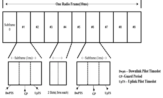
Type-1 frame structure works on both half duplex as well as full duplex FDD modes. The length of the radio frame is 10ms and each frame is divided into ten equally sized subframes of 1 ms each. Further a subframe is divided into two identical size slots of 0.5 ms each. So in 1 frame there are 20 slots of equal duration of 0.5msas shown in figure 1. In Frequency Division Duplex mode, for both the uplink and downlink transmission scheduling is done on a subframe basis. Each slot has 6 (extended cyclic prefix) or 7 (normal cyclic prefix) number of OFDm symbol, depending on whether normal or extended cyclic prefix is applied.
2.2 Type-2 LTE TDD mode systems
a Comprehensive review of modulation Techniques used in Long Term Evolution
special subframe. The special sub frame consist of three fields: Downlink Pilot Time Slot (DwPTS), guard Period (gP), uplink Pilot Time Slot (upPTS) as illustrated in figure 2. The frame structure can be configured in seven different subframe formats; however subframe 0 and 5 and DwPTS are reserved for downlink transmission. The subframe that appears after special subframe as well as upPTS, is always assigned to uplink transmission.
3. LTE DOwNLINK physICAL DATA AND CONTROL ChANNELs physical Broadcast Channel (pBCh)
When the user equipment try to connect first time with eNodeB in LTE system, there is inadequate knowledge about the system parameter, so for establishing a connection a robust frame structure is required. The physical broadcast
Figure 1: LTE Type-1 frame structure.
Kumari, S
Singal, TL channel transmits necessary parameters for preliminary access of the cell for the physical hybrid arQ indicator channel, downlink system bandwidth and ranging information. These parameters are carried in 14 bit long master information block. The physical broadcast channel can be accessible at the cell edge without any previous information of system bandwidth. Convolutional coder is used to code the master information block at the coding rate of 1/3 and mapped to 72 centre sub-carriers of the OFDm configuration. PBCH transmission is spread over four 10 ms radio frames to span a 40 ms period.
physical Downlink shared Channel (pDsCh)
Physical Downlink Shared Channel (PDSCH) is the major downlink data carrying channel in LTE which is scheduled by eNodeB B for the user. This is assigned to carry downlink data on a basis of two resource block for one Transmission Time Interval (1ms). It also transmit broadcast information and paging messages which is not transmitted by physical broadcast channel.
physical Multicast Channel (pMCh)
To carry multimedia Broadcast and multicast Services (mBmS) PmCH is employed. In PmCH the base station transmit with accurate time synchronization with the same modulated symbol for single frequency network
physical Downlink Control Channel (pDCCh)
The first 1, 2 or 3 OFDm symbols in a subframe is occupied by Physical Downlink Control channel. The main goal of this channel to carry scheduling information such as Downlink resource scheduling, uplink resource grant, uplink power control instructions and Indication for paging or system information.
physical Control Format Indicator Channel (pCFICh)
The main aim of the PCFICH is to notify the user equipment about the received signal format. It carries a control format indicator whose work is to indicate the number of OFDm symbols and broadcast on the 1st symbol of every subframe.
4. physICAL UpLINK DATA AND CONTROL ChANNELs physical Uplink shared Channel (pUsCh)
a Comprehensive review of modulation Techniques used in Long Term Evolution
to physical at the interval of 1ms.To reduce the overhead of upper layers and improve the performance it can be grouped together before sending.
physical Uplink Control Channel (pUCCh)
The uplink control information is broadcasted to eNodeB from user equipment. It also carries other control messages like HarQ aCK/NaCK, channel quality indicators, mImO feedback and scheduling requests. BPSK or QPSK modulation scheme is applied. With the help of pre-defined protocol user equipment transmits data to eNodeB.
physical Random Access Channel (pRACh)
The PraCH channel performs uplink timing and frequency synchronization. This is performed by user equipment after downlink synchronization. Zadoff Chu (ZC) sequence is used because of its properties. Within LTE this is the only non synchronized sequence transmission due to limited battery power. Cyclic prefix of length 103μs and guard time of 97μs with preamble duration of 800μs is applied to fit the preamble in one subframe length.
5. OFDMA sysTEM As LTE DOwNLINK
The OFDm is frequency division multiplexing in which sub-carriers are orthogonal to each other. It has been elected as a basic modulation technique for downlink in LTE because of robust transmission, low inter symbol interference and high spectral efficiency. In OFDma scheme the available spectrum is
Kumari, S
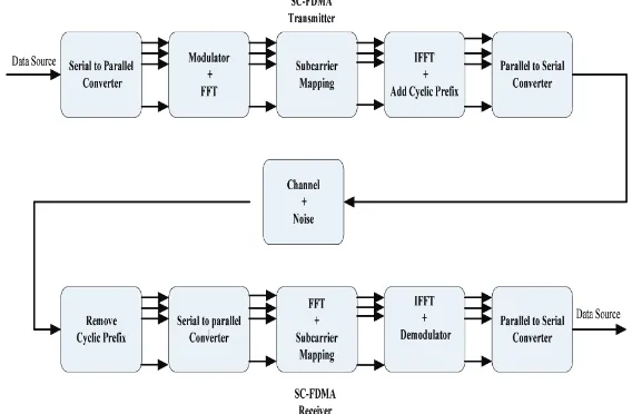
Singal, TL divided into number of orthogonal subcarriers. The subcarrier spacing for LTE system is 15 KHz with 66.67 μs OFDma symbol duration [4]. The high rate stream of data is transmitted through modulator, adaptive modulation schemes such as (BPSK, QPSK, 16-Qam, 64-Qam) is applied. The serial to parallel converter is used to convert the multilevel sequence of modulated symbols into parallel frequency subcarriers. See figure 3.
The next is IFFT block which translate the complex data symbols into time domain and OFDm symbols are generated. The significant advantage of OFDm is to suppress ISI, so to terminate the Inter symbol Interference
guard band is used. In LTE the guard band is also known as cyclic prefix and
the length of the cyclic prefix should be longer than the channel delay spread. The orthogonal frequency division multiple access technique uses two type of cyclic prefix i.e. normal and extended CP, which depend upon whether it is using in urban areas (high frequency) or rural area.at receiver, the CP is
first removed and then parallel to serial conversion of subcarriers sequence is
done The FFT stage converts the symbols into frequency domain followed by
equalizer and demodulation.
6. sC-FDMA system as LTE uplink
The functional block diagram for SC-FDma are almost common as OFDma for transmitter and receiver.SC-FDma uses additional N-point DFT stage at transmitter and an N-pint IDFT at receiver. Constellation mapper converts incoming data into signal constellation as per QPSK, 16-Qam, or
a Comprehensive review of modulation Techniques used in Long Term Evolution
Qam depending on channel conditions is shown in figure 4. These sequences are passed through the serial to parallel converter. The next block is Fast Fourier Transform, which transform representation of the QPSK/Qam symbols in frequency domain. Optional block of pulse shaping is followed by FFT to shape the output signal and if it is active then bandwidth extension occurs in the actual signal. These sequences are then mapped to uniformly spaced subcarriers
For time domain conversion the output modulated subcarriers are passed through IFFT. The remaining operation of transmitter is same as OFDma
7. REsULTs
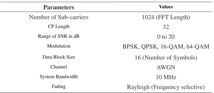
In this paper, the model of OFDma and SC-FDma is simulated using maTLaB communication tool box. To simulate the background noise of the channel the additive White gaussian Noise (aWgN) channel is used, which is described by SNr per sample. The number of sub-carriers is 1024 with cyclic prefix length 32.The range for signal to noise ratio ranges from 0 to 20 dB.
In no line of sight condition where multipath occurs, frequency selective fading is introduced in the channel. For this purpose rayleigh (Frequency selective) fading is employed.
Bit Error Rate (BER) Vs signal to Noise Ratio (sNR): The BEr is
defined as error bits divided by the total number of bits transmitted during
studied time interval. It is usually expressed as ten to a negative power. The
BEr is articulated in terms of Signal to Noise ratio for modulation scheme BPSK, QPSK, 16Qam, 64Qam.
BEr = error bits / number of bits sent
Table 1: Parameters used for simulation.
parameters Values
Number of Sub-carriers 1024 (FFT Length)
CP Length 32
range of SNr in dB 0 to 20
modulation BPSK, QPSK, 16-Qam, 64-Qam
Data Block Size 16 (Number of Symbols)
Channel aWgN
System Bandwidth 10 mHz
Kumari, S
Singal, TL density (NThe SNr is define as the ratio of bit energy (E0) and its unit is dB. b) to the noise power spectral
SNr = Eb / N0
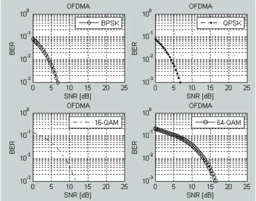
The graph shown below for the BEr vs SNr of OFDma and SC-FDma. The table shows the SNr value for the specific value of BEr 10-2 and 10-3. The SNr value is same for BPSK and QPSK 6.9 and 6.6 respectively for both OFDma and SC-FDma for BEr 10-3; If the BEr for 10-2 is taken then the value reduces to 4.6 and 5 respectively for OFDma and SC-FDma, however, a rapid change occur in 16-Qam and 64-Qam. The 64-Qam has maximum value of SNr 13.5 dB and 16.5 dB for BEr (10-2 and 10-3) which shows that
Figure 5: BEr vs. SNr of OFDma with adaptive modulation Table 2: BEr vs. SNr of OFDma and SC-FDma
modulation Scheme SNr (dB) for BEr 10
-2 SNr (dB) for BEr 10-3
OFDma SC-FDma OFDma SC-FDma
BPSK 4.6 5 6.9 6.6
QPSK 4.6 5 6.9 6.6
16-Qam 9.1 8.9 11.6 11.8
a Comprehensive review of modulation Techniques used in Long Term Evolution
64-Qudrature amplitude modulation is more efficient in terms Bit Error rate. See figure 5 & 6.
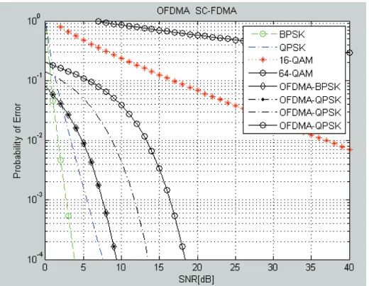
Error probability: The probability of error or error probability (Pe) is the rate of errors occurs in the received signal. For coherent detection, the symbol
Figure 6: BEr vs. SNr of OFDma with adaptive modulation.
Kumari, S
Singal, TL error probability of m-ary PSK and Qam in the aWgN channel is determined by following expressions
P Q 2E log m
N m
e b 2
0 ≅
2 sin π
Where, Eblog2m = E (Transmitted signal energy per symbol) [11], N0= Noise density in aWgN and Q=Q-function. See Figure 7.
The above graph show s the probability of error verses SNr for both the uplink (SC-FDma)and downlink(OFDma) scheme. In both technique SNr value increases for higher modulation.
8. CONCLUsION
For representing the system performance of any data link BEr is the significant parameter. From the result it is observed that for a constant value of the BEr, the SNr experiences less value for low modulation scheme like BPSK and QPSK but SNr rises for higher modulation schemes like 16-Qam and 64-Qam in both the uplink(SC-FDma) and downlink(OFDma) access techniques. So it can be concluded that system performance is improved in terms of BEr and SNr for low order modulation techniques, but if the bandwidth efficiency is considered then more data contains within in a given bandwidth for the higher modulation scheme as compared to low modulation techniques. Therefore modulation scheme used in LTE, there exist a trade-off between bandwidth efficiency and BEr. It is also concluded from the results that, as the order of modulation scheme increases, the error probability also increases. In nutshell, the selection of modulation scheme among the BPSK, QPSK, 16Qam, and 64Qam is quite crucial based on the result
REFRENCEs
[1] 3gPP TS 36.201 – v1.0.0, LTE Physical Layer – general Description, http://www.3gpp.org/ftp/Specs/archive/36%5Fseries/36.201/
[2] 3gPP TS 36.211 version 10.0.0 LTE; Evolved universal Terrestrial radio access (E-uTra); “Physical channels and modulation” (release 10)
[3] anna Zakrzewska, S. ruepp, m. Berger and F. D’andreagiovanni, “Biobjective optimization of radio access technology selection and resource allocation in heterogeneous wireless networks”, International symposium on modeling & optimization in mobile, ad-hoc & wireless networks, rawnet, pp.652-658, October 2013.
a Comprehensive review of modulation Techniques used in Long Term Evolution
[5] D. astély, E. Dahlman, a. Furuskar, Y. Jading, m. Lindstrom, and S. Parkvall, “LTE: The evolution of mobile broadband,” Communications magazine, IEEE, vol. 47, 2009, pp. 44–51. [6] g. Berardinelli, “air interface for next generation mobile communication networks: physical
layer design: a LTE-a uplink”, Department of Electronic Systems, pp.56-60, (2010). http://dx.doi.org/10.1109/mCOm.2009.4907406
[7] J. Liu, D. Wang, g. Shena, J. Pang, and Jun Wang,” Optimized Fairness Cell Selection for 3gPP LTE-a macro-Pico HetNets”, IEEE Vehicular Technology Conference (VTC Fall), ISSN 1090-3038, vol.10, no.6, pp.1-5, Sept. 2011
[8] K. Chang, P. Ho and Y. Choi,” Signal Design for reduced Complexity and accurate Cell Search/ Synchronization in OFDm-Based Cellular Systems”, IEEE Transactions on vehicular technology, vol. 61, no. 9, pp.4170-4175, Nov. 2012. http://dx.doi.org/10.1109/TVT.2012.2210919 [9] O. Bulakci, a. Bou Saleh, S. redana, B. raaf and J. Hämäläinen, “Enhancing LTE-advanced
relay deployments via relay cell extension”, 15th international OFDm-workshop, Hamburg, germany, Sep. 2010
[10] S. Fulani and Q. Liang, “Physical layer test trials and analysis of call drops and real time throughput versus channel capacity of the long term evolution (4g) technology”, International Journal of electronics Engineering, vol. 9, no. 3, pp.120-130, 2011.
[11] S. Sesia, I. Toufik, m. Baker, “LTE The umTS Long Term Evolution from theory to practice”,2009 John Wiley & Sons Ltd. http://dx.doi.org/10.1002/9780470742891