Copyright © The Author(s). All Rights Reserved. Published by American Research Institute for Policy Development DOI: 10.15640/jea.v7n2a8 URL: https://doi.org/10.15640/jea.v7n2a8
1 School of Civil Engineering and Architecture, Zhejiang University of Science and Technology Hangzhou, China. Email: ([email protected]). Phone +79673702344
2 School of Civil Engineering and Architecture, Zhejiang University of Science and Technology, Hangzhou, China. Email: ([email protected]). Phone +8613858056598
3 School of Civil Engineering and Architecture, Zhejiang University of Science and Technology, Hangzhou, China. 4 School of Civil Engineering and Architecture, Zhejiang University of Science and Technology, Hangzhou, China.
Analyses of Artificial Ground Freezing with Carbon Dioxygen to Protect Foundation Pit
from High Ground Velocity Water Flow
Vyzhimov Artem
1, Xia Jianzhong
2, Huang Zhuye
3& Zhang Haojie
4Abstract
The ground water can effect on time of artificial frozen wall formation. The traditional method using cold brine is not suitable for high-speed water flow. The method using the solid carbon dioxygen can close the frozen wall faster due to lower freezing temperatures of freezing column. In this paper, we simulated the situation with the use of columns filled with carbon dioxygen installed in the zone of the higher influence of groundwater on soil freezing. We collected data and processed the results with further recommendations for using this method. In this work, the construction of an analytical model was carried out in the Comsol Mylti physics software package, which justified its use in solving soil freezing problems.
Keywords: Artificial ground freezing, groundwater flow, refrigerants, temperature field, seepage
1 Introduction
1.1 Artificial ground freezing with solid carbon dioxygen
As the development of deep foundation and tunnel technology, ground water is one of the problems in the construction of underground structures. Their presence prevents the conduct of mining, tunneling and construction works, threatening the safety of the building under construction, reduces the stability and the strength of the surrounding array, which can lead to its destruction.
The method of AGF (Artificial Ground Freezing) has been known for over a hundred years (Vakulenko & Nikolaev, 2015). In urban underground construction, brine freezing method is widely used(Nicholson , 2015), (Andersland & Ladanyi, 2004). But a significant disadvantage of brine freezing is that it consumes a fairly long preparatory period where have place to be installation of the brine network, in addition installation and commissioning of the freezing station are needed. One of the ways to reduce the cost of works on freezing of small amounts of soil, achieving lower temperatures and reducing the duration of the preparatory period is the use of non-brine freezing methods. Liquid nitrogen freezing acts more quickly than the non-brine system and has been used effectively for short intervent (Tunnel Constraction guidelines 04 - Guidance Note on Ground Freazing Constraction). When using liquid nitrogen, the temperature of the wall of the freezing column can reach minus 196 °C, which can significantly reduce the time of active freezing. However, the technology of work with the use of liquid nitrogen is technically complex and dangerous (direct human contact with this refrigerant or its saturated vapors can cause serious harm to health).
This is the simplicity of work organization, a small period of preparatory work prior to freezing, a significant (2-3 times) reduction in the time for creating an ice-ground barrier of a given size and configuration. (Nikolaev P. V., 2014), (Nikolaev P. V., 2016). At normal atmospheric pressure (0.101 MPa), the sublimation temperature of solid carbon dioxide is -78.9 ° C. (Shuplik & Borisenko, 2006)
The most common and easiest way to freeze soils using solid carbon dioxide is by placing solid carbon dioxide directly in the freezing column (Sabenkova, Galkin, Stoyakova, & Besfamilnaya, 2018). Due to the heat coming from the soil, solid carbon dioxide sublimates. The temperature in the column drops to -78.9 °C. As sublimation in the column intensively creates carbon dioxide gas, which as a result of increasing pressure in the freezing column, rises to the ground surface and goes into the atmosphere by removing heat from the surrounding area (Pimenova, 1982).
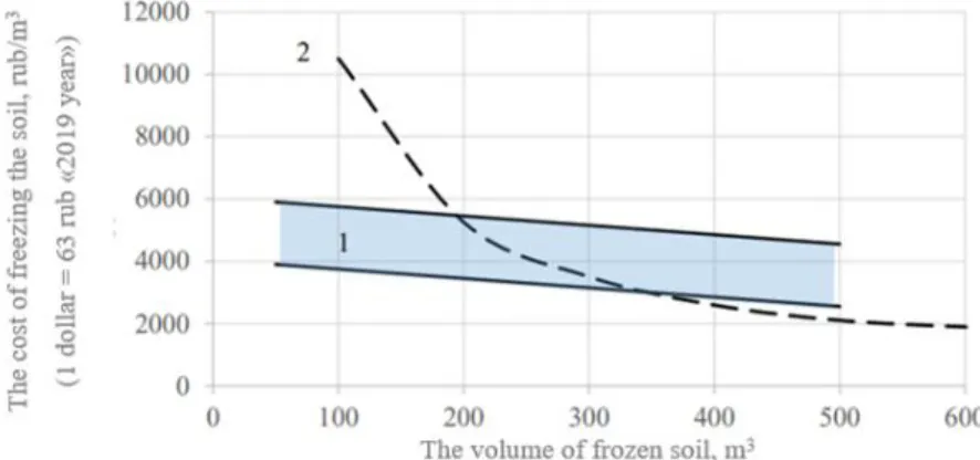
As for economy, the solid carbon dioxygen have a good perspective in small construction sites which volume of expected frozen soil is less than 300m3(Shuplik M. N., Justification and development of resource-saving
technologies, 1989)[Figure 1]
Figure 1. Change in the cost of freezing 1m3 soil depending on the volume of the frozen soil. Area 1–freezing using solid carbon dioxide; curve 2 – brine freezing with using PHU-50 freezing plant. (Shuplik & Borisenko, 2006)
1.2 Ground water flow in AGF
Groundwater flow with high velocity can significantly slow down the formation time of artificial frozen wall. (Rui & Quan, 2016)Water contributes to additional heat. Higher flow velocity, the greater heat could be approached to the freezing column.
The frozen wall developed quickly and achieved closure in a short time under the strong freezing intensity. (Wei, Wang, & Yang, 2018)
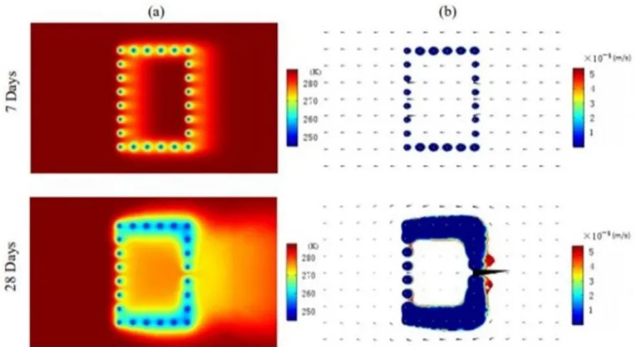
In article (Rui & Quan, 2016), the authors analyzed the situation at the construction site in Guangzhou. The [Figure 2] below shows the results of their research, from which it can be seen that if groundwater washes the foundation pit, it has a different effect on the formation of the ice wall. The walls being perpendicular to the groundwater flow are subject to slow down the freezing process, while the walls located in the direction of the flow do not undergo significant changes. At the same time, the up-steam walls are most exposed to groundwater, while down-steam are less.
Figure 2 (a) Temperature distribution and (b) permeability coefficient (temperature below 0°C) results &
Darcy’s velocity field (black arrows) for project example at various times (Rui & Quan, 2016)
2 Numerical analytical model
In our study, we used parameters close to the previous study we introduce in this paper, except that we will fill the columns on the upsteam wall with solid carbon dioxide. In view of its lower sublimation temperatures -78.9ºC, which in turn will create a temperature of the outer wall surface of about -75 ºC. Lower temperature will lead to a significant reduction in time and cost for freezing areas that are most exposed to heat from groundwater.
In our simulation, we made a few assumptions that reduced the time it took to solve the problem and reduced the power consumption of the computer while preserving the research logic
a) The study was carried out in 2D-dimensional model
b)A soil layer is a continuous, homogeneous and isotropic porous medium
c) The pipe wall temperature is based on the brine temperature -30°С and the temperature of columns with solid carbon dioxygen -75°C.
d) The temperature on the depth of freezing columns are constant
2.1 The mesh
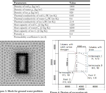
The mesh automatically constructed by COMSOL are shown on Figure 3, and foundation pit design on Figure 4. As we can see, behind the columns has finer amount of polygons. This means that more polygons are needed in order to calculate all the processes occurring near the columns.
● The area marked with a blue frame indicates the area where the brine freezing method is used.
● The area highlighted in red indicates the area using carbon dioxide filled columns. The same zone is the zone most susceptible to defrosting from heat transferred by groundwater.
● Groundwater movement is taken from left to right.
● Dimensions of the study site 20x20 m2
● Column pitch 1m
● Along the foundation pit there are 9 columns vertically and 5 columns horizontally.
● The diameter of the columns 0.1 m
Table 1 The materials characteristics
Parameters Value
Density of soil ρs (kg/m3) 1800
Density of water ρw (kg/m3) 1000
Density of ice ρi (kg/m3) 920
Thermal conductivity of soil λs (W/(m·K)) 0.85
Thermal conductivity of water λw(W/(m·K)) 0.6
Thermal conductivity of ice λi(W/(m·K)) 2.14
Heat capacity of soil Cs (J/(kg·K)) 1220
Heat capacity of waterCw (J/(kg·K)) 4200
Heat capacity of ice Ci (J/(kg·K)) 2100
Porosity n 0.4
Permeability coefficient k (m/d) 5
Figure 3. Mesh for ground water problem Figure 4. Design of excavation pit
Five control points were set to control the stability of the simulation. A, B, C to control temperature changes. D, E points to control groundwater velocity. Points A, B, C are set at a distance of 0.5 meters from the freezing columns.
According to (Trupak, 1974) frozen fence is waterproof if the thickness of frozen soil layer in the lock of two frozen cylinders exceeds 150-200 mm. Following this, the velocity sensors are located along the axes of the freezing column with displacement of 100 mm towards the outside. If the velocity at these points reaches zero, the walls can be considered waterproof.
3 Results and discussion
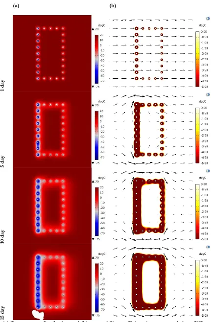
(a) (b)
1 day
5 day
10 day
15 day
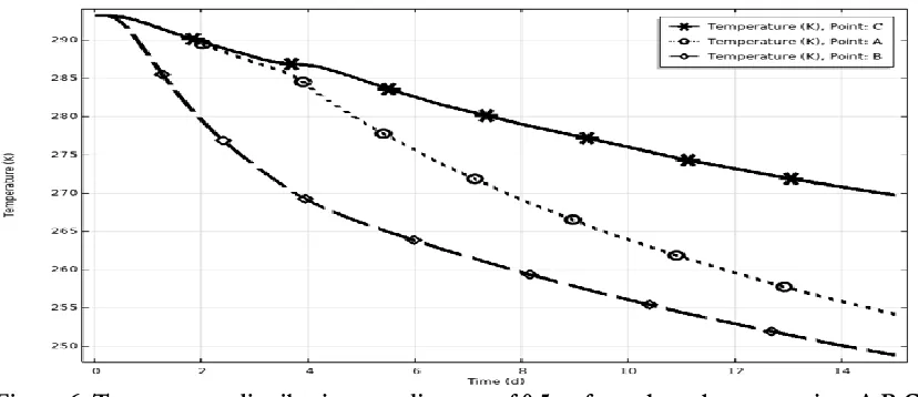
As expected, the growth of the ice-ground fence using solid carbon dioxide is faster compared to the brine method. Thermocouples reading temperature from time at a distance of 0.5m from the freezing columns give us the following results, which are presented in Figure 6. On it we see three lines characterizing the temperatures at point A, B and C. Point C characterizes the temperature dependence typical for the brine freezing method. Points A and B for the method using solid carbon dioxide. Comparing the results of lines C and B, we see that the temperature drops much faster when using solid carbon dioxide.
Liquid nitrogen will give even more successful results in view of extremely low temperatures, but its use in urban conditions with small volumes of construction sites will not be justified. The cost of the material remains extremely high without the ability to reuse it. Also extremely low temperatures can cause injuries at construction sites.
It is also worth noting the asymmetry of the growth of the ice fence. The flow of water creates a large influx of heat, which is unevenly discharged along the column. This leads to asymmetry. It is possible that the front of the ice wall will be tangent to the freezing columns. This should be taken into account during design, so that during excavation does not destroy the layer of the ice wall, which can lead to flooding of the foundation pit.
Temperature graphs at a distance of 0.5 m from the column to the left (point 7.5, 10) and right (point 8.5, 10) are shown in Figure 6.
Figure 6. Temperature distribution at a distance of 0.5 m from the column at points A,B,C
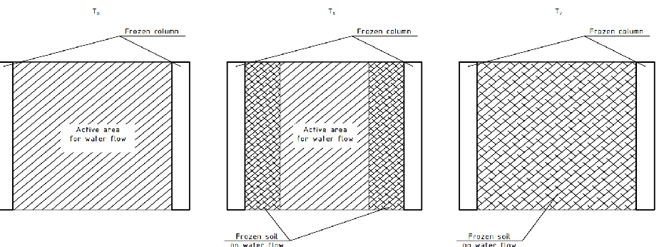
Analyzing the obtained velocity graphs, we see a number of interesting features. First, the columns using solid carbon dioxide formed a waterproof wall in 3.5 days after the start of freezing, in contrast to the brine method, which coped with this task only after 12 days. It is also very interesting to analyze the increase of the velocity before closing the frozen wall. This happening due to a decrease in the area of the active section, which leads to an increase in velocity. At the moment the wall is fully formed, the speed drops to zero.
Figure 8.The active area changes during the process of artificial ground freezing
Figure 9. Relationship between ground water velocity and closure time
After analyzing our results with the results of the experiment (Rui & Quan, 2016) we have the following. Replacement in up-steam wall coolant on solid carbon dioxygen, decrease the time of closure for at least 5 days. It is also worth considering the fact that the initial temperature and groundwater temperature in our simulation is 5 degrees higher and equal to 20°C not 15°C.
Dry ice proved to be a great solution for faster freezing up-steam wall. Its presence leads to a more rapid freezing of adjacent walls, due to the initial decrease in groundwater temperatures of the oncoming flow
0 5 10 15 20 25 30 35 40 45 50 55 60
0.0 0.1 0.2 0.3 0.5
C
losure
ti
me, d
Ground water velosity, m/d
Up-steam wall (solid CO2) Down-steam wall (cold brine) Bottom and top (cold brine)
On [Figure 10] we can observe that the wall using solid carbon dioxide closes much faster at speeds of less than 0.3 m/d, despite the fact that it is located in noticeably harsher conditions than the down steam wall using cold brine. At high speeds, the situation changes dramatically. Due to higher groundwater temperatures near up stream wall and flow rates above 0.5 m/d, the water does not have time to freeze. The flow temperature is dropping. By the time the groundwater reaches down steam, the temperature of the groundwater when flowing along the first row of columns has time to cool to 5-10°C. As a result, down steam wall is easier to cope with such a load.
4 Conclusions
1) From the above analysis we can see that using solid carbon dioxygen for AGF decrease the time for continues wall formation. According to results, solid carbon dioxide form waterproof wall in 3.5 day, while brine method only after 12 days. Lower temperature of solid carbon dioxygen is better to high velocity underground water flow in comparison with brine method.
2) Also talking forward using solid carbon dioxygen on the building site together with brine method can decrease the total price of AGF.
3) Using solid carbon dioxygen in column located on the up steam site to the flow of ground water flow decrees the time of ice wall formation. In fact that combined use can twice decrease the time compare to the mono use of thebrine method.
4) Soft ComsolMultiphysics is fit for the analysis of such problem. The software package can adequately and quickly solve the tasks. But it is also worth noting that the solution of the problem with prediction of the front of the ice fence is very problematic. In the context of the soil characteristics. Soils with different dispersed composition have different temperature of water–ice phase transition due to a different microstructure of soil and salinity of water. The analysis of the problem of this kind will require enormous computer power and time, which takes it beyond the boundaries of adequate civil engineering tasks.
5) Compare with the other method, solid carbon dioxygen main advantage is that it can afford low temperatures and cheap in use and convenience.
In this article, we justified the use of dry ice on the construction site in conjunction with the classical brine method. Replacing the cold brine in the zones with the maximum load, due to the presence of a large heat inflow from groundwater, on dry ice, we got positive results. Dry ice not only significantly reduces the time of formation of the ice-ground wall, but also more suitable in conditions of flooded soil with a high velocity of groundwater movement. When the transfer of heat ocurred due to the movement of water afterwards it requires large freezing capacity, and the limited temperature of the brine method, negates the technology of using the brine method of freezing soils.
The use of solid carbon dioxide increases the possibilities of using the method of soil freezing and takes an intermediate place between the brine method and the use of liquid nitrogen. The ease of use compared to the brine method, and the relative low cost compared to liquid nitrogen, makes the method of artificial freezing using solid carbon dioxide very attractive in modern construction.
In addition have to mention that use of the dry ice can be an excellent solution to the problems of an already designed project. The technology does not need in a special equipment. Already existing columns for the brine method are excellent for the use with dry ice, which makes the technology suitable for eliminating the consequences of an improperly designed brine network.
The technology of freezing using dry ice remains extremely unexplored, despite the huge database accumulated over several decades. The number of times it is used in real construction is still extremely small.
References
Andersland, O. B., & Ladanyi, B. (2004). Frozen Ground Engineering. Second Edition. John Wiley & Sons.
Nicholson , P. (2015). Soil Improvement and Ground Modification Methods. USA: Elsevier and Butterworth-Heinemann. Nikolaev, P. V. (2014). Experience and Prospects of Development of Energy Saving Technologies of Ground
Freezing in Urban Underground Construction. 367-371.
Nikolaev, P. V. (2016). Rationale parameters of ground freezing technology with the use of solid carbon dioxide in underground
construction. Moscow: National Research University of Technology.
Rui, H., & Quan, L. (2016). Simulation of Heat Transfer during Artificial Ground Freezing. Excerpt from the Proceedings
of the 2016 COMSOL Conference in Munich, (pp. 1-6). Munich.
Sabenkova, N. A., Galkin, N. S., Stoyakova, K. L., & Besfamilnaya, E. M. (2018). Analysis of variation methods of Artificial Ground Freezing. Technic, technologies, Engineering, 32-35.
Shuplik, & Borisenko. (2006). The technology of artificial freezing of soils with the use of solid refrigerants in underground construction. 381-384.
Shuplik, M. N. (1989). Justification and development of resource-saving technologies. Moscow.
Shuplik, M. N., & Borisenko, V. N. (2004). Modern ways of freezing grounds with the application of solid cryoagents.
UDK 622.253.35, 227-232.
Tunnel Constraction guidelines 04 - Guidance Note on Ground Freazing Constraction. (n.d.). Association of Geotechnical & Geoenvironmental Specialists (Hong Kong), 1-5.
Vakulenko, I., & Nikolaev, P. V. (2015). Analysis and prospects of development of the method of artificial freezing of soils in underground construction. UDC 622.272:622.238, 338-346.