Volume 62, 2019, Pages 1–9
SUMO User Conference 2019
Coupling SUMO with a Motion Planning Framework for
Automated Vehicles
Moritz Klischat, Octav Dragoi, Mostafa Eissa, and Matthias Althoff
Technische Universit¨at M¨unchen, Fakult¨at f¨ur Informatik, Lehrstuhl f¨ur Robotik, K¨unstliche Intelligenz und Echtzeitsysteme,
Boltzmannstraße 3, 85748, Garching, Germany. [email protected]
Abstract
Testing motion planning algorithms for automated vehicles in realistic simulation envi-ronments accelerates their development compared to performing real-world test drives only. In this work, we combine the open-source microscopic traffic simulator SUMO with our software framework CommonRoad to test motion planning of automated vehicles. Since SUMO is not originally designed for simulating automated vehicles, we present an inter-face for exchanging the trajectories of vehicles controlled by a motion planner and the trajectories of other traffic participants between SUMO and CommonRoad. Furthermore, we ensure realistic dynamic behavior of other traffic participants by extending the lane changing model in SUMO to implement more realistic lateral dynamics. We demonstrate our SUMO interface with a highway scenario.
1
Introduction
Automated driving requires extensive testing due to the complexity of driving tasks and the variety of possible situations. Therefore, virtual testing is important in order to accelerate the development of automated vehicles and reduce development costs. An integral part of testing motion planning algo-rithms under realistic conditions is the realistic simulation of surrounding traffic participants. Several simulation frameworks exist for testing functionalities of driver-assistance systems or automated vehi-cles; however, most of them are traditionally based on predefined scenarios. On the other hand, many simulators only consider microscopic simulation of traffic without automated vehicles.
To test automated vehicles under more realistic conditions, we couple the traffic simulator SUMO [18] with our open-source software framework CommonRoad1 for benchmarking and motion planning of automated vehicles. Through our interface, arbitrary motion planners can be tested with traffic participants controlled by SUMO. The integrated vehicle models in SUMO enable a closed-loop sim-ulation with traffic participants reacting to vehicles controlled by the motion planner, which we refer to as host vehicles from now on. Our interface is able to control multiple host vehicles and thus is able to handle collaborative planning tasks. We also improve the realism of other traffic participants in SUMO by extending existing lane-changing models to generate physically-feasible trajectories through a lightweight implementation.
1.1
Related Work
1.1.1 Coupling of Traffic Simulators
In previous works, traffic simulators are coupled with driving simulators for testing manually-driven vehicles, see e.g., [4,6,20]. Less work exists on coupling automated vehicles with traffic simulations. One of the few works combines SUMO with the simulator Virtual Test Drive (VTD) for driver assistance systems [22,23]. VTD is used for high-fidelity simulations of vehicles close to the host vehicle, whereas SUMO is used for less relevant traffic participants.
Simulators focusing on generating behaviors for learning-based approaches are CARLA [9] and AirSim [24]. These simulators include modeling of sensor data and use game engines like Unreal and Unity. The recent project Apollo [5] aims at providing a complete framework for the development of automated vehicles. Simulators from the robotics community such as Gazebo [13] and VRep [10] can also be used for simulating automated vehicles. For instance, Gazebo is coupled with SUMO in [12] to simulate traffic participants. Further work enabling the simulation of the perception of the host vehicle through a combination of robotic simulators can be found in [8,21,27].
1.1.2 Lane-Changing Models in SUMO
Modeling of longitudinal motion in SUMO is already in a mature state, implemented in a variety of car-following models [16]. Also, there already exists much work on modeling high-level lane changes with a strong focus on the decision making process [11,15,17]. While it is possible to specify the duration of a lane change, the resulting trajectories are not generally physically feasible. Since motion planning algorithms typically only consider physically-possible motions, this can cause false positive errors. Semrau et. al. [23] developed a sub-lane model that enables a more detailed representation of lateral motion, including lane changes. Since this model is based on a lateral discretization of the lane, it increases the complexity of the simulation with regard to the number of considered maneuvers. Furthermore, it is not fully compatible with other functionalities of SUMO.
1.2
Contributions
Most of the existing simulators are based on complex software frameworks and aim at covering the whole workflow, from perception to a high-fidelity physics simulation. In contrast, our goal is to provide an interface to a lightweight, open-source simulation environment that especially targets research projects on motion planning. Furthermore, our approach for synchronizing lane changes of host vehicles with SUMO yields more realistic behaviors of other traffic participants compared to previous work. By extending lane-changing models in SUMO, vehicles feature a more realistic lateral movement with continuous acceleration instead of constant lateral velocity only.
2
Coupled Simulation
We first introduce the motion planning framework based on CommonRoad for interfacing motion planners and then present the realized interface to SUMO afterwards.
2.1
CommonRoad
CommonRoad is a Python tool for reading CommonRoad [1] benchmark files which provides basic functionalities for motion planning of automated vehicles. CommonRoad benchmarks consist of a map, static and dynamic obstacles, and a planning problem defined by an initial state and goal regions for one or multiple cooperating vehicles. The same structure is present in a CommonRoad scenario object. Based on CommonRoad, we have developed a software framework2 for motion planning, including a collision checker, reachability analysis [25], and set-based prediction of traffic participants [2,14].
2.2
Map Conversion
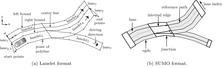
Prior to starting the simulation, a common road network needs to be defined in the CommonRoad and SUMO formats. Road networks in SUMO are represented byedges andjunctions. Edges connect two junctions and consist of one or multiple lanes whose order is specified by indices; lanes are defined by the lane width and a reference path consisting of an array of vertices (polylines). At junctions, edges are linked viainternal edges, denoting which outgoing lanes are reachable from which incoming lanes of respective edges.
In contrast, road networks in CommonRoad are represented by lanelets [7], which are defined by their left and right bounds modeled by polylines. Lanelets are connected via successor-predecessor relations, as well as via adjacency relations. A lanelet is denoted as the successor of another lanelet if the starting vertices of the successor coincide with the final vertices of the predecessor. As shown in Fig.1, junctions or merging lanelets are modeled by having multiple successors connected to a lanelet. Lanes of a road are also defined implicitly by the left and right adjacency relations of lanelets.
left bound right bound start points end points driving direction point of polyline
lanelet1
lanelet2
lanelet 3 lanel et4 lanelet5 lane1
lane2,3
lane1 lane2 lane3 center line x y u w
(a) Lanelet format
junction internal edge
reference path lane index
lane
egde
(b) SUMO format.
Figure 1: Comparison of map formats.
To represent the same road network in the SUMO and CommonRoad formats, a conversion from SUMO to CommonRoad is performed by first converting SUMO to the similar OpenDRIVE [19] format using the tool NETCONVERT from SUMO. From that format, a map in CommonRoad format is created using our converter from OpenDRIVE to lanelets [3]. Alternatively, OpenDRIVE maps can be used as a common basis for SUMO and CommonRoad maps. An example for a map conversion is shown in Fig.2.
2.3
Vehicle Interface
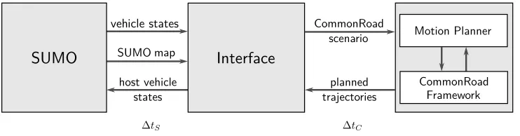
The interface between the simulations in SUMO and CommonRoad is shown in Fig. 3. During the co-simulation, the states of traffic participants and the trajectories xH(t) ∈ R4 of host vehicles are
exchanged via commands from the TraCI API of SUMO. While the trajectories of host vehicles are controlled by one or several motion planners, all other vehicles are simulated in SUMO. In SUMO, the states of traffic participantsxT(t)∈R4 are defined by x- and y-position, velocity, and orientation.
These states are read before every planning cycle of the motion planner with duration ∆tC∈R+ using
TraCI and converted to a CommonRoad scenario object. Note that SUMO can be simulated with
smaller time increments ∆tS=
∆tC
d ,d∈Nto enhance the accuracy of the simulation.
2.4
Synchronization of the Host Vehicles with SUMO simulation
In order to expose the host vehicles to other traffic participants, their planned trajectories for the subsequent time increment ∆tC are transferred through the interface. The interface interpolates the
(a) SUMO (b) CommonRoad
Figure 2: Roundabout in SUMO format converted to CommonRoad map format.
∆tS ∆tC
Figure 3: Synchronization between SUMO and Motion Planning Framework.
cannot include host vehicles, we override states of vehicles at each time increment ∆tSusing the TraCI
commands moveToXY for the position and orientation and setSpeed for velocity. Before activating the interface to the motion planner, the interface can initiate a simulation in which the host vehicles are controlled by SUMO for the time intervalt∈[0, tstart], so that the motion planner can focus on
interesting situations.
2.4.1 Lane-Change Synchronization
One strength of SUMO is the integration of vehicle models implementing the reactions of traffic par-ticipants to their surrounding vehicles. When performing a lane change, vehicles in the target lane slow down to maintain a safe distance once they are notified about the lane change intent according to [11]. However, this implementation does not work in conjunction with the command moveToXY, because then other vehicles are not notified about the lane change and thus only react once the host vehicle has entered their lane.
guarantee that the trajectoryxH,s(t) conforms to the driven trajectoryxH(t) planned by the motion
planner. However, in return for a more realistic simulation of traffic behaviors and a simple integration with existing vehicle models in SUMO, we accept a small error between both trajectories.
To ensure that the errore(t) =kxH,s(t)−xH(t)k2does not exceed a defined thresholdemax∈R+,
the interface switches back to moveToXY once the condition e(t) < emax is violated (see line 12 in
Algorithm1). This condition is monitored throughout the lane change. To reduce the error of both trajectories, we extendchangeLaneand the lane changing models to additionally accept the lane-change durationtlas an input, instead of using a global default duration. The durationtlis computed by the
functionDetectLaneChange(xH([tk, tk+th])) that checks whether the planned trajectory intersects
with a lane that is laterally adjacent to the currently occupied lane at any time during the planning interval [t, t+th]. Byth∈R+ we denote the planning horizon of the motion planner.
Algorithm 1Host Vehicle Synchronization with SUMO simulation
Require: MotionPlanner, TraCI instance, simulation durationtend, planning horizonth, time increment of motion planner∆tC
1: t←0
2: performing lane change←f alse 3: while t < tend do
4: xH([t, t+th])←MotionPlanner.GetPlannedTrajectory(tk)
5: tl, lane change planned←DetectLaneChange(xH([tk, tk+th])) 6: if lane change planned =truethen
7: if performing lane change6=truethen
8: TraCI.changeLane(tl)
9: performing lane change ←true
10: else
11: if e(t)> emaxthen
12: TraCI.MoveToXY(xH(tk))
13: performing lane change←f alse
14: end if
15: end if
16: else
17: TraCI.MoveToXY(xH(tk))
18: end if
19: TraCI.simulationStep()
20: t←t+ ∆tC 21: end while
3
Continuous Lane Change in SUMO
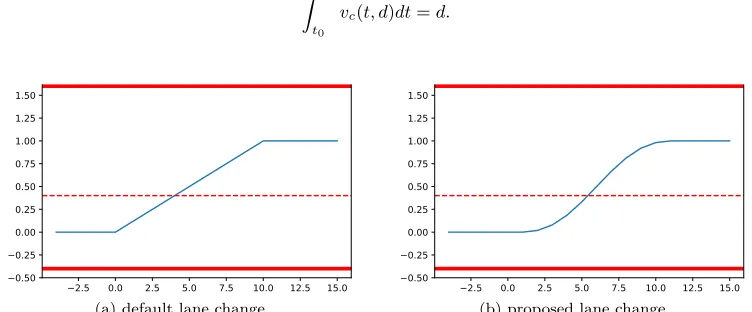
In this section, we suggest an improvement for lane-change handling of vehicles in SUMO. The previous implementation [11] uses either instantaneous lane changes or constant velocity for lateral motion as illustrated in Fig.4. We propose lane changes with a more realistic acceleration.
To be compatible with previously-developed lane-changing models, we extend the existing function-ality of SUMO. Let us briefly recall the current implementation first. Lane-change behavior is defined in the classMSAbstractLaneChangeModel. Specific lane-changing models inherit from it and implement different behaviors regarding decision making related to lane changes. In the functioncomputeSpeedLat, constant-velocity lane changes are implemented where at every time steptk= ∆tS·k,k∈[0, n] of the
computed. Usingv(tk), the lateral distance is computed:
d(tk+1) =d(tk) + ∆tS·v(tk+1).
To integrate a lane change with continuous acceleration, we compute the lateral velocityvc(t) which
considers the boundary conditions
v(0) = 0, v(tn) = 0,
d dtv(t) t=0
= 0, d dtv(t)
t=tn
= 0
for enforcing a smooth transition at the beginning and end of the lane change. This is achieved by using the polynomial
vc(t, d) =d c t2(tn−t)2, (1)
where the constantcis chosen in order to travel the lateral distanced∈R+ during the lane change,
i.e.,
Z tn
t0
vc(t, d)dt=d.
−2.5 0.0 2.5 5.0 7.5 10.0 12.5 15.0 −0.50 −0.25 0.00 0.25 0.50 0.75 1.00 1.25 1.50 Original SUMO
(a) default lane change
−2.5 0.0 2.5 5.0 7.5 10.0 12.5 15.0 −0.50 −0.25 0.00 0.25 0.50 0.75 1.00 1.25 1.50
Continuous 10 Steps
(b) proposed lane change
Figure 4: Continuous lane change compared to the previous implementation in SUMO.
3.1
Implementation
If the lane-change durationtlis globally fixed as currently implemented in SUMO, the termc t2(tn−t)2
in (1) can even be computed offline for alltksince it is independent ofd. However, our implementation
can also be applied to individually set lane-change durations, as mentioned in Section2.4.1. In the base case where no lateral speed constraint is given, calling the functioncomputeSpeedLat returns v(tk),
and the current stepk →k+ 1 is incremented accordingly as shown in Algorithm2. Lane-changing models in SUMO can also constrain the lateral speed limitvmax. To comply with the implementations
of these models, the velocity for the computation ofd(tk) is limited (c.f. line9) and a second iterator
m∈Nis introduced. The iteratormis only incremented after the traveled distanced(tk+1) exceeds
the distance without consideration ofvmaxattm(c.f. line11of Algorithm2).
4
Numerical Example
We demonstrate the presented combination of our motion planning framework with SUMO through a highway scenario with multiple vehicles interacting with the host vehicle. We use a sampling-based motion planner [26], which utilizes the CommonRoad collision checker3 and a constant-velocity
pre-diction for surrounding vehicles. Time increments of ∆tC = ∆tS = 0.1 s are used and the planning
horizonthof the motion planner is 2 s.
Algorithm 2Smooth Lane Change
Require: total lateral distance d, lane-change durationtl, maximal velocityvmax 1: k= 0
2: m= 0
3: while m·∆tS < tl do 4: if vmax=∅then
5: d(tk+1)←d(tk) + ∆tsvc(tk, d)
6: k←k+ 1
7: m←m+ 1
8: else
9: d(tk+1)←d(tk) + ∆tsmin(vmax, vc(tm, d))
10: k←k+ 1
11: if d(tk+1)≥Pl
i=1vc(tm, d)∆ts then
12: m←m+ 1
13: end if
14: end if
15: end while
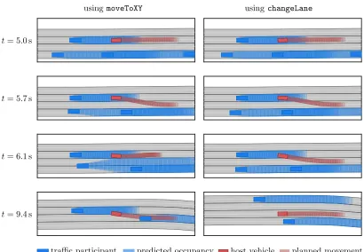
The trajectory planner of the host vehicle drives with constant velocity when starting a lane change at t = 5.2 s. To demonstrate the synchronization using changeLane presented in Algorithm 1, we compare the results of our algorithm to a synchronization with SUMO throughMoveToXY only. As shown in Fig.5for using MoveToXY, the vehicle in the rightmost lane starts an overtaking maneuver, even after the host vehicle clearly started a lane change but is still in its lane. As a result, the host vehicle is forced to abort its lane change att = 6.1 s in order to avoid a collision and only performs the lane change after letting the other vehicle pass. In contrast, the other vehicle does not perform a lane change when synchronizing the host vehicle with SUMO through usingchangeLane, because it is notified earlier.
5
Conclusions
We have shown how to couple SUMO with our motion-planning framework for testing automated vehicles. The proposed algorithm for synchronizing lane changes with SUMO yields a more realistic behavior of other traffic participants, and our extension of lane-change models yields more realistic motions of vehicles. The presented interface is published onhttp://commonroad.in.tum.de.
In the future, we plan to integrate the presented framework into our CommonRoad benchmark suite [1]. Our suite currently consists of scenarios with predefined trajectories for all traffic participants, enabling benchmarking of motion planners. Scenarios with interactive traffic participants will extend the scope of the benchmarks to further aspects of decision making.
Acknowledgements
t= 5.0 s
t= 5.7 s
t= 6.1 s
t= 9.4 s
usingchangeLane
usingmoveToXY
predicted occupancy
traffic participant host vehicle planned movement Figure 5: Comparison of lane changes realized by the functionschangeLane and moveToXYin a highway scenario at different timest.
References
[1] M. Althoff, M. Koschi, and S. Manzinger. CommonRoad: Composable Benchmarks for Motion Planning on Roads. InProc. of the IEEE Intelligent Vehicles Symposium, pages 719–726, 2017. [2] M. Althoff and S. Magdici. Set-based prediction of traffic participants on arbitrary road networks.
IEEE Transactions on Intelligent Vehicles, 1(2):187–202, 2016.
[3] M. Althoff, S. Urban, and M. Koschi. Automatic Conversion of Road Networks from OpenDRIVE to Lanelets. InProc. of the 2018 IEEE Int. Conf on Service Operations and Logistics, and Infor-matics, pages 157–162, 2018.
[4] M. Aramrattana, T. Larsson, J. Jansson, and A. N˚abo. Extended Driving Simulator for Evaluation of Cooperative Intelligent Transport Systems. InProceedings of the 2016 annual ACM Conference on SIGSIM Principles of Advanced Discrete Simulation, pages 255–258, 2016.
[5] Baidu Apollo Team. Apollo: Open Source Autonomous Driving, 2017.
[6] M. Barthauer and A. Hafner. Coupling traffic and driving simulation: Taking advantage of SUMO and SILAB together. InEPiC Series in Engineering, volume 2, pages 56–44. EasyChair, 2018. [7] P. Bender, J. Ziegler, and C. Stiller. Lanelets: Efficient Map Representation for Autonomous
Driving. InProc. of the IEEE Intelligent Vehicles Symposium, pages 420–425, 2014.
2017: Towards Simulation of Autonomous Mobility, 2017.
[9] A. Dosovitskiy, G. Ros, F. Codevilla, A. Lopez, and V. Koltun. CARLA: An Open Urban Driving Simulator. InProc. of the 1st Annual Conference on Robot Learning, pages 1–16, 2017.
[10] M. F. E. Rohmer S. P. N. Singh. V-REP: a Versatile and Scalable Robot Simulation Framework. InProc. of the Int. Conference on Intelligent Robots and Systems (IROS), 2013.
[11] J. Erdmann. Lane-changing model in SUMO. InProc. of the SUMO2014 Modeling Mobility with Open Data, volume 24.
[12] M. Garzon and A. Spalanzani. An hybrid simulation tool for autonomous cars in very high traffic scenarios. In2018 15th International Conference on Control, Automation, Robotics and Vision, ICARCV 2018, pages 803–808, 2018.
[13] N. Koenig and A. Howard. Design and use paradigms for Gazebo, an open-source multi-robot simulator. InIEEE/RSJ Int. Conf. on Intelligent Robots and Systems, pages 2149–2154, 2004. [14] M. Koschi and M. Althoff. SPOT: A Tool for Set-Based Prediction of Traffic Participants. In
Proc. of the IEEE Intelligent Vehicles Symposium, pages 1679–1686, 2017.
[15] D. Krajzewicz. Kombination von taktischen und strategischen Einfl¨ussen in einer mikroskopis-chen Verkehrsflusssimulation. Fahrermodellierung in Wissenschaft und Wirtschaft, 2. Berliner Fachtagung f¨ur Fahrermodellierung, pages 104–115, 2009.
[16] S. Krauß. Microscopic modeling of traffic flow: Investigation of collision free vehicle dynamics. 1998.
[17] S. Li, Y. Wu, Z. Xu, and X. Lin. Improved lane-changing model for VANETS in sumo. The 7th IEEE/Int. Conf. on Advanced Infocomm Technology, pages 260–266, 2014.
[18] P. A. Lopez, M. Behrisch, L. Bieker-Walz, J. Erdmann, Y. P. Flotterod, R. Hilbrich, L. Lucken, J. Rummel, P. Wagner, and E. Wiebner. Microscopic Traffic Simulation using SUMO. InProc. of IEEE Conf. on Intelligent Transportation Systems, pages 2575–2582, 2018.
[19] H. G. M. Dupuis, M. Strobl. OpenDRIVE 2010 and beyond — status and future of the de facto standard for the description of road networks. In Proc. of the Driving Simulation Conference Europe, pages 231–242, 2010.
[20] T. Nguen That and J. Casas. An integrated framework combining a traffic simulator and a driving simulator. Procedia - Social and Behavioral Sciences, 20:648–655, 2011.
[21] J. L. F. Pereira and R. J. F. Rossetti. An integrated architecture for autonomous vehicles simula-tion. InProceedings of the 27th Annual ACM Symposium on Applied Computing - SAC ’12, pages 286–292, 2012.
[22] M. Schiller, A. Knoll, M. Dupius, D. Krajzewicz, and A. Kern. Multi-resolution Traffic Simulation for Large-Scale High-Fidelity Evaluation of VANET Applications. InSUMO User Conference 2015 - Intermodal Simulation for Intermodal Transport, pages 17–36.
[23] M. Semrau, J. Erdmann, B. Friedrich, and R. Waldmann. Simulation framework for testing ADAS in Chinese traffic situations. InSUMO 2016 Conference Proceedings, pages 103–113, 2016. [24] S. Shah, D. Dey, C. Lovett, and A. Kapoor. AirSim: High-Fidelity Visual and Physical Simulation
for Autonomous Vehicles. InField and Service Robotics, 2017.
[25] S. S¨ontges and M. Althoff. Computing the Drivable Area of Autonomous Road Vehicles in Dynamic Road Scenes. IEEE Transactions on Intelligent Transportation Systems, 19(6):1855–1866, 2018. [26] M. Werling, S. Kammel, J. Ziegler, and L. Gr¨oll. Optimal Trajectories for Time-Critical Street
Sce-narios using Discretized Terminal Manifolds.International Journal of Robotic Research, 31(3):346– 359, 2012.