COMPARATIVE PERFORMANCE ANALYSIS OF
MODELING, CONTROL AND SIMULATION OF
DC-DC BOOST CONVERTER WITH PV CELL USING
MPC AND NARMA-L2 CONTROL
*G.C.Sowparnika,PG Student
**A.Sivalingam, Associate Professor
***M.Thrumarimurugan, Associate Professor & Head
*Department of Chemical Engineering, Coimbatore Institute of Technology, Coimbatore, India.
** Department of Chemical Engineering, Coimbatore Institute of Technology, Coimbatore, India.
*** Department of Chemical Engineering, Coimbatore Institute of Technology, Coimbatore, India.
ABSTRACT
DC-DC converters are switched power converters. They are used to convert one DC voltage to another. Boost converters are inordinately used in industry as well as in research. The model of the converter system varies from ON state to OFF state. The major drawback is the unlimited supply of voltage and current. Hence a MPC is implemented to produce a constant voltage with varying input supply. The performance of MPC is further improved using NARMA-L2 control as shown in the simulation results in MATLAB.
Keywords: converters, industry, MPC, performance, simulation, voltage.
INTRODUCTION
DC-DC boost converters usually provide variations in output voltage with respect to input voltage. The free supply of voltage and current leads to malfunctioning of the boost converter. Control techniques such as analog and digital methods are used [1].
DC-DC converters are intrinsically non-linear circuits and it is difficult to obtain accurate models which influences dynamic behaviour. The DC-DC converter inputs are generally unregulated DC voltage input and the required outputs should be a constant or fixed voltage. Application of a voltage regulator is that it should maintains a constant or fixed output voltage irrespective of variation in load current or input voltage.
79 Generally, DC-DC boost converters consist of power electronic circuits and semiconductor devices which act as the switch control for the system. In this article, the responses of the MPC and NARMA-L2 control are determined using MATLAB [2].
MODELING OF BOOST CONVERTER
The boost converter is a high efficiency step-up DC/DC switching converter. The converter uses a transistor switch, typically a MOSFET, to pulse width modulate the voltage into an inductor.
A. Basic Configuration of Boost Converter
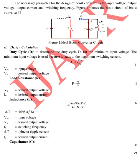
The necessary parameter for the design of boost converter is the input voltage, output voltage, output current and switching frequency. Figure 1 shows the basic circuit of boost converter [3].
Figure 1.Ideal Boost Converter Circuit
B. Design Calculation
Duty Cycle (D): to determine the duty cycle D, for the minimum input voltage. The minimum input voltage is used because it leads to the maximum switching current.
D=
1-Vin = input voltage
Vo = desired output voltage Load Resistance (R):
R=
Vo = desired output voltage Io = desired output current
Inductance (L):
L=
Vin = input voltage
Vo = desired output voltage fs = switching frequency
= inductor ripple current
Io = desired output current Capacitance (C):
(1)
(2)
(3)
C=
Io = desired output current D = duty cycle
fs = switching frequency = output ripple voltage
= inductor ripple current
ESR = equivalent series resistance of the capacitor
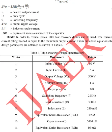
Diode: In order to reduce losses, ultra fast recovery diodes can be used. The forward current rating needed is equal to the maximum output current. From the above equations the design parameters are obtained as shown in Table I.
Table I.Table showing Design Specifications
Sr. No. Parameters Values
1. 2. 3. 4. 5. 6. 7. 8. 9. 10. 11.
Input Voltage (Vin)
Input Current (Iin)
Output Voltage (Vo)
Output Current (Io)
Duty cycle (D)
Switching frequency (fs)
Load Resistance (R)
Inductance (L)
Equivalent Series Resistance (ESL)
Capacitance (C)
Equivalent Series Resistance (ESR)
60 V 5 A 300 V 1 A 0.8 2 KHz 300 Ω 240 mH 0.5Ω 5000 μF 16 mΩ
*Units: V- volt, A- ampere, Ω- ohms, mH- milli Henry, μF- micro Farad
STATE SPACE MODELING
81
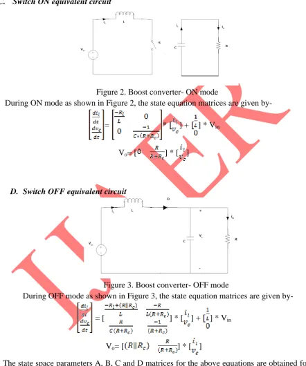
C. Switch ON equivalent circuit
Figure 2. Boost converter- ON mode
During ON mode as shown in Figure 2, the state equation matrices are given by-
= * ] + ] * Vin
Vo= [ ] * [ ]
D. Switch OFF equivalent circuit
Figure 3. Boost converter- OFF mode
During OFF mode as shown in Figure 3, the state equation matrices are given by-
= [ ] * [ ] + ] * Vin
Vo= [ ] * [ ]
The state space parameters A, B, C and D matrices for the above equations are obtained for ON and OFF states. By averaging techniques the determined matrices are:
Aavg =
Bavg = ]
(6)
(7)
(8)
Cavg = [ ]
Davg = [0] Using MATLAB, the output transfer function obtained is
CONTROLLER FOR BOOST CONVERTER
The boost converter should always maintain constant voltage with variations in the input parameters. In order to maintain a stable output in the converter, an appropriate control signal should be applied. In practice the switching network is highly non-linear. An accurate mathematical modeling of the switching network is very difficult to obtain. In addition there are also reported problems of the supply voltage and load current fluctuating over a wide range. A controller is designed and modeled which yields the control transfer function and the controller transfer function. Therefore an online Model Predictive Controller is implemented to achieve a proper system performance [5]. This performance is further improved using NARMA-L2 control. The occurrence of oscillatory behaviour of the boost converter is mainly caused by the switching operation of the semiconductor device. In order to stabilize the transient response of the system, MPC and NARMA-L2 control is implemented. Pulse Width Modulation (PWM) technique is the often used switching control method [6]. By small signal modeling technique, the control transfer function is determined.
The transfer function for the compensator is determined as
Therefore the overall control transfer function is
E. Model Predictive Controller (MPC)
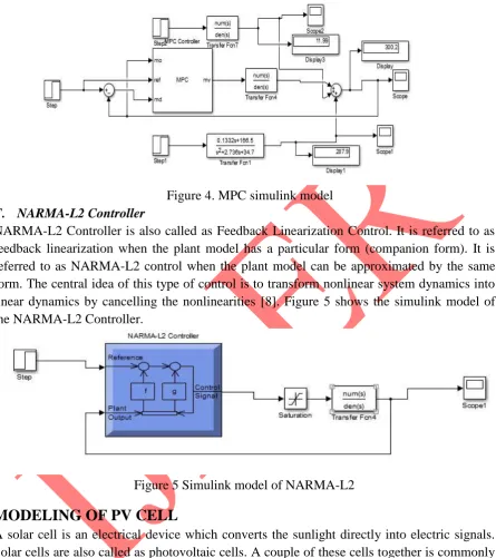
Model Predictive Controller is an advanced technique in process control which is used in process industries such as chemical plants and oil refineries. It is also used in power system models. MPC depends on dynamic models of the process. The advantageous factor is that it predicts the future output with respect to the output obtained from the model and the residues obtained between the plant and model output. Based on the future event, MPC takes the control action accordingly. In order to improvise the performance obtained from PID controller, the MPC is implemented and the output response is shown in the results and discussions. Figure 4 shows the simulink model of the Model Predictive Controller [7].
(10)
(12)
83 Figure 4. MPC simulink model
F. NARMA-L2 Controller
NARMA-L2 Controller is also called as Feedback Linearization Control. It is referred to as feedback linearization when the plant model has a particular form (companion form). It is referred to as NARMA-L2 control when the plant model can be approximated by the same form. The central idea of this type of control is to transform nonlinear system dynamics into linear dynamics by cancelling the nonlinearities [8]. Figure 5 shows the simulink model of the NARMA-L2 Controller.
Figure 5 Simulink model of NARMA-L2
MODELING OF PV CELL
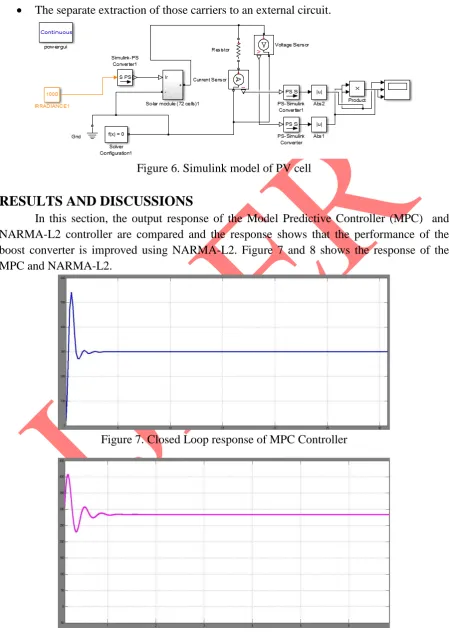
A solar cell is an electrical device which converts the sunlight directly into electric signals. Solar cells are also called as photovoltaic cells. A couple of these cells together is commonly called as solar panels or photovoltaic panels. The modeling of the solar panel is done to obtain a DC voltage source of 60V using MATLAB. Figure 6 shows the simulink model of Photo-Voltaic (PV) cell.
Solar cells are described as being photovoltaic irrespective of whether the source is sunlight or an artificial light. They are used as a photo detector, detecting light or other electromagnetic radiation near the visible range, or measuring light intensity. The operation of a photovoltaic (PV) cell requires 3 basic attributes [9]:
The separate extraction of those carriers to an external circuit.
Figure 6. Simulink model of PV cell
RESULTS AND DISCUSSIONS
In this section, the output response of the Model Predictive Controller (MPC) and NARMA-L2 controller are compared and the response shows that the performance of the boost converter is improved using NARMA-L2. Figure 7 and 8 shows the response of the MPC and NARMA-L2.
85
CONCLUSION
In this article, the boost converter with the desired specification is obtained. The output responses are compared with the MPC and the NARMA-L2 controller. The ANNs controller provided an improved response with the reduction in error of the converter model. This work can be further improved by implementing Sliding Mode Control (SMC), Neuro-fuzzy systems (ANFIS) and Hybrid fuzzy systems.
REFERENCES
[1] Sowparnika G C, Sivalingam A and Thirumarimurugan M, “Evaluation of Control Techniques in DC-DC Converters”, International Journal of Emerging Technology & Research, vol.2, no.4, pp.1-8, 2015.
[2] Dhivya B S, Krishnan V and Ramaprabha R, “Neural Network Controller for Boost Converter”, In Proceedings of International Conference on Circuits, Power and Computing Technologies [ICCPCT-2013], pp.246-251, Jan, Research Gate, 2013. [3] Brigitte Hauke, “Basic Calculation of a Boost Converter’s Power Stage”, Application
Report SLVA372C, Texas Instruments, 2014.
[4] Abdul Fathah, “Design of Boost Converter”, Department of Electrical Engineering, National Institute of Technology, Rourkela 2013.
[5] Apekshit Bhowate and Shraddha Deogade, “Comparison of PID Tuning Techniques for Closed Loop Controller of DC-DC Boost Converter” International Journal of Advances in Engineering & Technology, vol.8, no.1, pp.2064-2073, 2015.
[6] Zeigler J G and Nichols N B, “Optimum Settings for Automatic Controllers”, Transaction of ASME, vol.64, pp. 759-768, 1944.
[7] Holkar K S and Waghmare L M, “An Overview of Model Predictive Control”, International Journal of Control and Automtion, vol.3, no.4, pp. 47-64, 2010.
[8] Mark Hudson Beale, Martin T. Hagan and Howard B. Demuth, “Neural Network Toolbox- User’s Guide”, MATLAB, The Math Works Inc., 2015.