http://www.sciencepublishinggroup.com/j/ogce doi: 10.11648/j.ogce.20160406.12
ISSN: 2376-7669(Print); ISSN: 2376-7677(Online)
The Research of Distributed PMG Stabilized Power Supply
Based on Speed-Regulating of Prime Mover
Gongfei He, Bingyi Zhang
Electrical Engineering Department, Shenyang University of Technology, Shenyang, China
Email address:
[email protected] (Gongfei He), [email protected] (Bingyi Zhang)
To cite this article:
Gongfei He, Bingyi Zhang. The Research of Distributed PMG Stabilized Power Supply Based on Speed-Regulating of Prime Mover. International Journal of Oil, Gas and Coal Engineering. Vol. 4, No. 6, 2016, pp. 60-65. doi: 10.11648/j.ogce.20160406.12
Received: October 28, 2016; Accepted: December 29, 2016; Published: January 27, 2017
Abstract:
As the demand for distributed power supply increases, the permanent magnet generator with many advantages has been widely used. In order to overcome the defect that the permanent magnet generator can't maintain the output voltage constantly by adjusting the excitation current the same as with the electrically excited synchronous generator, this paper presents the stabilized control strategy based on speed-adjusting of prime mover, that is use the rectified DC voltage as feedback through adjusting the speed of the prime mover to achieve no static error control. This paper introduces the control principle of the power generation technology, based on the research of the external characteristics of permanent magnet generator and operating characteristics of the prime mover analysis of the feasibility of this control method. The curve of the prime mover's speed varies with load obtained by co-simulation when maintaining the generator's output voltage constantly. The control strategy proposed in this paper is the organic combination of the prime mover and generator, which simplifies the control the structure of generator set. This power generation technology is suitable for the distributed power supply spontaneous for personal use. The stabilization of DC voltage can avoid the requirement of constant frequency and the stable DC power supply can supply the power for DC load or through the inverter for AC load.Keywords:
Speed-Regulating of Prime Mover,PMG, DC Stabilized, Distributed Power Supply, Co-simulation1. Introduction
In recent years, due to the phenomenon of electricity shortage caused by the imbalance of economic development and resource distribution, the role of distributed power in the development of the national economy has become increasingly obvious. As the main power supply or standby power supply, it is widely used in the fields of large ships, field engineering, military demand, disaster relief and other fields [1-2]. The control purposes of power generators is to stabilize the output voltage and frequency, the methods of regulating generator excitation, controlled rectifier and PWM inverter often used to stabilize voltage, the methods of regulating the speed of prime mover, regulating the AC excitation of the doubly fed generator and AC-DC-AC converter technology often used to stabilize frequency [3-4]. The traditional electrically excitation synchronous generator set to stabilize frequency by constant prime mover speed, to stabilize output voltage by regulating excitation current, directly output three-phase AC with constant
frequency and constant voltage, the generator has brush, slip ring, with complex structure, and the excitation power accounted for (3~5)% of the generator rated capacity consumed in the motor rotor in the form of heat, which will increase the fault factors of the system, and reduce the efficiency of the system. With the rapid development of power electronics technology and the demand of the large capacity power supply, generator set with rectifier load has been widely research and application, at this time, the PMG with high efficiency, simple structure and high torque density can be applied [5].
have studied the control system of the PMG set from different aspects by different methods.
The output voltage regulation method of PMG has studied by some scholars, the references [6] describes how to reduce the voltage regulation rate of PMG from motor design perspective. The references [7-8] introduces a hybrid excitation control technology, by changing the excitation winding current to change the air gap synthetic magnetic field, realizing the regulation of output voltage. The references [9] introduces a kind of vector control strategy to change the air gap synthesis magnetic field by adjusting armature reaction magnetic field to stabilize the output voltage. The method mentioned in the references [10] is that the output terminal of the generator provided with a rectifier, and the DC output voltage is kept constant by adjusting the trigger angle of the controllable rectifier.
For the generator set with rectifier load, because of the existence of rectifier, there is no need to maintain the output frequency of the generator constant, that is, there is no need to maintain the speed of prime mover constant to stabilize frequency. According to the load characteristic curve of internal combustion, the internal combustion running on the 75%~85% load rate, has the lowest fuel consumption, lower or higher than this area will increase the consumption of fuel, while the prime mover speed of traditional generator is constant, so in low load, will result in high fuel consumption and poor economy. In order to meet the electricity demand of 50/60Hz, the prime mover speed is usually fixed in 3000r/min, 1500 r/min or 1000 r/min, and in order to meet the demand of electric power communication 50/60Hz, the prime mover speed is usually fixed in the standard limit of 3000r/min, 1500 r/min or 1000 r/min. However the high speed prime mover and generator can be used in the application of this technology, both the prime mover and generator can greatly reduce its volume and weight [11].
2. Analysis of PMG's Output Voltage
In order to achieve a better voltage stabilizing control of the generator set, the influence factors of the PMG's output voltage need to be analyzed by using the analytic method in theory, to analysis the scope and extent of the change of generator's output voltage affected by various parameters, in order to provide theoretical basis to maintenance generator's output voltage constant.
When the effect of saturation of the magnetic circuit is neglected, the phase diagram of the PMG is shown in Figure 1, and
θ
is power angle,ϕ
is power factor angle, ψ0is innerpower factor angle, E•0 is excitation electric potential, Φ•o
is main magnetic flux, I• is armature current, R1 is stator
phase resistance, U• is terminal voltage, Id
•
is the direct
axis component of the armature current, Iq
•
is the quadrature
axis component of armature current, Xd is direct axis
synchronous reactance, Xq is quadrature axis synchronous
reactance [12].
Figure 1. Phase diagram of the PMG.
From the phase diagram can be seen that the output voltage of the PMG is related to the power factor angle, and the power factor angle is related to the load characteristics of the generator. When there is a rectifier between the generator and the load, the power factor depends on the type of rectifier. When it is uncontrollable diode rectifier, the output voltage and current of the generator in the same phase, and the generator power factor is 1, when it is controllable IGBT rectifier, can arbitrarily adjust the size and phase of the current, but it with high cost and large loss [13]. Because the generator's output voltage of the proposed control strategy can be a constant, the diode rectifier control mode is adopted, the power factor angle
ϕ
=0, according to the phase diagram of PMG,we can summarize that:0 2 2 1
q
q d
cos X
U E IR
cos X sin X θ
θ θ
= −
+ (1)
According to the formula (1), when it is rectifier load and the saturation of the magnetic circuit is neglected, the output voltage of the PMG is only related to the six parameters of
0
E
, I ,R
1,θ
,X
d and Xq. The parameters ofX
d andq
X are related to the magnetic circuit structure of the
generator, the diversity of PMG's circuit structure mainly for the different of the permanent magnet's position and magnetizing direction. The diversity of magnetic circuit structure determines the different proportions of the two parameters
X
d and Xq, due to the salient pole PMG withq
d
X
X
γ
=
(2)From the formula of PMG's electromagnetic torque we can know that The power angle of the generator is positively related to the load. In order to analyze the relationship between the output voltage of the generator and the load, when ignoring the voltage drop of the armature winding, the relationship curves between the output voltage and the power angle of the generator are drawn according to the formula (1), shown in figure 2.
Figure 2. Curves of output voltage varies with power angle.
It can be seen from the figure 2 that with different
γ
, the change trend of generator's output voltage varies with power angle is different, the greater theγ
is, the lower voltage regulation rate of the generator, whichγ
=1 represents hidden pole generator. When 1<γ
< 2, the output voltage of PMG will decreased obviously with the increase of power angle, whenγ
>2, at the beginning, the output voltage of the generator will be increased with the increase of power angle, after reaching the maximum value and then decreases with the increase of power angle, the greaterγ
is, the tendency is more obvious. By comparison, it can be found that with the increase ofγ
the voltage regulation rate can be significantly reduced, and even the voltage regulation rate of the generator can be zero or negative. Obviously, due to the uncertainty of the load, whatever the generator'sγ
is, it is difficult to maintain the output voltage constant, only by reasonable design the value ofγ
to reduce voltage regulation rate of the generator, to reduce fluctuation range of the generator's voltage.The three parameters of
R
1,X
d and Xq are fixed for theexisting generator, and the two parameters I and
θ
will change with the change of the load. When the load change, if not change generator's no-load EMF, the output voltage of the generator must be changed with the change of I andθ
, at this time, only by changing generator's no-load EMF to maintain the output voltage constant. According to the phase EMF expression of the generator, for the existing generator,when generator's winding connection is determined, the no-load EMF only depends on the speed of the generator. Therefore, when the load changes, we can change the speed of the generator to maintain the output voltage of the generator constant, that is to change the speed of the prime mover to maintain the output voltage of the generator constant.
3. Principle of Stabilized Power Supply
3.1. Structure Diagram of Stabilized Power Supply
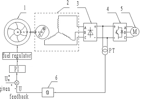
The PMG stabilized power supply based on speed-regulating of prime mover mentioned in this paper is realized by the voltage close loop feedback control technology, the structure diagram of stabilized power supply control system is shown in Figure 3, and 1 is prime mover, 2 is PMG, 3 is uncontrollable diode rectifier, 4 is inverter, 5 is load, 6 is voltage feedback coefficient. The operation principle of the generator set is that the PMG outputs three-phase AC power under the driving of prime mover, the three-phase AC power is converted to DC power through the uncontrollable diode rectifier, the DC power can be supplied directly to the DC power load, and can also be supplied to the AC power load after converted by the inverter. When the load changes, the output voltage of the generator is kept constant at given value by adjusting the speed of prime mover, the voltage transformer (PT) collects the DC voltage outputted by the diode rectifier as the voltage feedback signal, real- time regulation the fuel control mechanism of the prime mover by voltage close loop feedback control. When the load changes, by increasing or decreasing the supply of fuel to increase or decrease the speed of prime mover, so as to realize the adjustment of generator set's output voltage without static error.
Figure 3. Structure diagram of the power supply.
3.2. Dynamic Regulating Process of Generator Set
When the load changes, the process to realize the adjustment of generator set's output voltage without static error by the voltage close loop feedback control is as follows: When the load is constant, the voltage feedback signal is equal to the given signal, the output voltage of the generator is maintained at a given value. If the load suddenly increases, the increasing of the armature current will result in the decreasing
0 10 20 30 40 50 60
100 120 140 160 180 200 220 240 260
power angle (degree)
p
h
a
s
e
v
o
lt
a
g
e
(
V
)
γ=1
γ=1.5
γ=2
γ=2.5
γ=3
of generator's voltage, at the same time, because of the increasing of load torque, the speed of prime mover will decreased, which will further decreasing generator's voltage, resulting the voltage feedback signal U is less than the voltage given signal
U
n∗
, ∆Un>0, the PI regulator output control
signal to increases the fuel supply of the prime mover to increase its speed and torque, until the output voltage of the generator is stabilized at given value. If the load suddenly decreases, the decreasing of the armature current will result in the increasing of generator's voltage, at the same time, because of the decreasing of load torque, the speed of prime mover will increased, which will further increasing generator's voltage, resulting the voltage feedback signal U is greater than the voltage given signal
U
n∗, ∆Un<0, the PIregulator output control signal to decreases the fuel supply of the prime mover to decrease its speed and torque, until the output voltage of the generator is stabilized at given value. The purpose of maintaining the output voltage of the generator constant achieved by adjusting the speed of the prime motor, and overcome the defect of PMG that can't stabilize output voltage by regulating the excitation current.
4. Simulation and Experimental
Research
4.1. Simulation Research on the System
According to the formula (1), if you want to obtain the external characteristic curve of the generator by the analytical method, the real-time accurate parameter values of Xd and
q
X are needed. The diversity of PMG's rotor structure leads to the complexity distribution of the magnetic field, coupled with the impact of the strong coupling of stator and rotor, the saturation of magnetic and other factors, it is difficult to get accurate parameter values of Xd and Xq , the common
analytical method, the finite element method and the experimental method are difficult to obtain real-time effective reactance parameter values of Xd and Xq. Therefore, this
paper using Ansoft Maxwell and Simplorer softwares to conduct the field circuit coupling simulation to obtain the external characteristic curve of the generator.
In order to facilitate the compared and analyzed of simulation data and the measured results, the finite element software is used to establish the simulation model of an existing surface-mounted PMG. The rated parameters of the prototype are:
I
N=20A, UN=180V,E
0=220V,R
1=0.8Ω,N
f
=25Hz,n
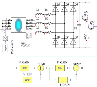
N =100r/min. According to the actualparameters of the prototype, the Maxwell Ansoft is used to establish the simulation model of the prototype, and it is imported into the voltage loop simulation circuit which is built by Simplorer, and the simulation model shown in Figure 4.
The voltmeter VM1 is used to measure the DC voltage and output feedback signal, the output of SUM2 is as the given speed of the prime mover Engine, V_REF is a DC voltage of a given value, inductance L1, L2, L3 used to equivalent generator's end inductance, resistance R2, R1, R3 used to equivalent generator's phase resistance, C1 for the filter capacitor, resistor RL is used to simulate the resistive load, by changing the value of RL to equivalent the change of load.
Figure 4. Circuit model of co-simulation.
0
+ V
VM1
E
n
g
in
e
S
U
M
2
.V
A
L
R
O
T
_
V
R
O
T
A
AM1
RL R1
R2
R3 L1
L2
L3
GND
R
O
T
_
V
R
O
T
D2
D1 D3
D4
D5
D6
GAIN
N_GAIN
I
I_GAIN
CONST
V_REF
SUM1 SUM2
GAIN
P_GAIN
C1 A-in
B-in C-in M-in
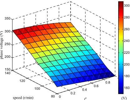
In order to show the relationship between the output voltage of the generator, the speed of the prime mover and the armature current intuitively, taking prime mover speed and armature current as variable, Through the open loop simulation, the natural characteristic surface figure of the generator is shown in Figure 5. Given the prime mover running at rated speed, to change the armature current by changing the value of RL, getting the generator's characteristic curve shown in Figure 7 by open-loop simulation, the horizontal axis is represented by the per unit of armature current.
Figure 5. The surface figure of PMG’s natural characteristic.
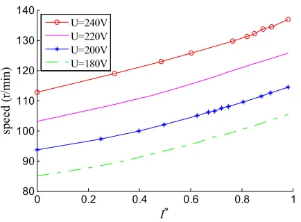
Figure 6. Simulation curves of speed varies with load.
According to the distribution and change trend of the color in Figure 5, which representatives the size of generator's output voltage, it is clear to see when the load changes, how to adjust the speed of the prime mover to maintain the output voltage constant, and it can be seen how the output voltage of the generator varies with the load fluctuation when the prime mover speed is constant, the rule of change is consistent with the conclusion of the previous analytical analysis.
Respectively, the output phase voltage of the generator maintained at 240V, 220V, 200V and 180V, the relationship curves between the speed of prime mover and the size of load obtained by the closed loop simulation shown in Figure 6.
4.2. Experimental Research on the System
In the experiment, two motor with the same rated parameters fixed on the towing platform, and the prototype is used as generator and the three-phase output terminal of the generator is connected with three phase resistance box, another as the prime mover driven by inverter. In the experiment, the speed of generator is maintained at rated speed, by changing the resistance of the resistance box to realize the armature current of the generator increased from 0 to rated current, the external characteristic curve of the generator obtained by experiment shown in Figure 7.
Figure 7. External characteristic curves.
You can see from the Figure 7, the changing trend of prototype's external characteristic curves obtained by simulation and experiment is basically consistent, which proves the feasibility and reliability of co-simulation method, co-simulation method can auxiliary the analyze and design of generator. According to the experimental results, the no-load back EMF of the generator is 218V, when rated load, the output voltage of the generator is 175.4V, and the inherent voltage regulation rate of the generator is:
0 218 175.4
% % 24.29%
175.4
N
E U
U U
−
∆ = = - = (3)
It can be known that the voltage regulation rate of the hidden pole PMG is too high to meet the load demand without reasonable measures. Although the salient pole structure can be used to reduce the voltage regulation rate of the PMG, However, no matter what kind of rotor structure is used, it is difficult to maintain the output voltage of generator during the change load, and it is difficult to meet the load demand on the quality of the power supply voltage.
In the experimental process, the generator is subjected to pure resistive load, the speed of prime mover in the change of resistance of resistance box is adjusted at the same time, the output voltage of the generator is kept constant at 240V, 220V, 200V and 180V respectively, obtaining the relationship curves between the speed of prime mover and the per unit of armature 0 0.2
0.4 0.6
0.8 1
80 100 120 140 150 200 250 300 350
(V) I*
speed (r/min)
p
h
as
e
v
o
lt
a
g
e
(
V
)
160 180 200 220 240 260 280 300
0 0.2 0.4 0.6 0.8 1
80 90 100 110 120 130 140
I*
sp
ee
d
(
r/
m
in
)
U=240V U=220V U=200V U=180V
0 0.2 0.4 0.6 0.8 1
170 180 190 200 210 220 230
I*
p
h
a
se
v
o
lt
a
g
e
(
V
)
current shown in Figure 8.
Figure 8. Experiment curves of speed varies with load.
It can be seen from the figure 8, as long as corresponding increase the speed of prime mover with the increase of load can maintain the output voltage constant at given value. The relationship between the speed of prime mover and the load is an approximate parallel curve. And with the increase of load, the speed of the prime mover is gradually increasing, and the experimental results are consistent with the simulation results in Figure 6. The speed change rate of the prime mover is defined as:
N 0
0
n n
n n
−
∆ = (4)
In the formula above,
n
N is the speed of prime mover atrated load,
n
0 is the speed of prime mover at no-load,according to the experimental data in order to maintain the output voltage constant at 240V, 220V, 200V and 180V, respectively, the speed change rate of the prime mover is 19.35%, 21.83%, 22.76% and 22.98%. For different given values of the voltage, the variation range of the prime mover's speed is basically the same, which is similar to the inherent voltage regulation rate of the generator.
5. Conclusion
The control strategy of stabilized power supply proposed in this paper changes the conventional mode of the control of the prime mover and the generator separately, the organic combination of the prime mover and the generator is carried out by the control system, the adjustment of PMG's output voltage without static error is realized by the method of speed regulation, overcomes the defects of PMG's output voltage is uncontrollable. The feasibility of the control strategy is analyzed by the principle of the prime mover and the operation characteristic of the generator, the external characteristic curve of the generator is obtained by the co-simulation, the relationship curve between the speed of the prime mover and the change of the load is obtained, the experimental results are consistent with the simulation results,
and consistent with the theoretical analysis results. The power generation technology proposed in this paper can be applied to the distributed generation in independent operation, which has a certain reference value for the application and research of the PMG set.
References
[1] Zhang Li, Yuan Haiwen, Lv Hong, Yuan Haibin. Fault diagnosis for independent power-supply system using multi-agent information fusion [J]. Journal of Beijing University of Aeronautics and Astronautics, 2010, 36 (8): 936-944.
[2] Guo Xin, Yuan Haiwen, Zheng Dun, Mi Hanguang. Study on Inverter Side DC Voltage Control of Active Power Filter for Isolated Power System [J]. Low-voltage Apparatus, 2011, 19: 44-48.
[3] Wang Fengxiang. Application and Development Tendency of PM Machines in Wind Power Generation System [J]. Transactions of China Electrotechnical Society, 2012, 27 (3): 12-24.
[4] Simoes M G, Bose K B. Fuzzy logic based intelligent control of a variable speed cage machine wind generations system. IEEE Trans. On Power Electronics, 1997, 12 (1): 234-239.
[5] Luo junling. Research on Testing and Voltage Regulation for Off-grid Permanent Magnet Synchronous Generator [D]. Huaqiao University, 2013.
[6] Liu Lin, Wu Qiang. Research on Low Voltage Regulation of Permanent Magnet Generator [J]. Ship E E Electrical Technology, 2011, 31 (8): 10-12.
[7] Zhang Hongjie, Tang Renyuan. Theory of hybrid excitation permanent magnet synchronous generator and parameter calculation [J]. Journal of Shenyang Polytechnic University, 2000, 22 (5): 393-395.
[8] Zhu Xiaoyong, Cheng Ming, Zhao Wenxiang. An overview of hybrid excited electric machine capable offield control [J]. Transactions of China Electrotechnical Society, 2008, 23 (1): 30-39 (in Chinese).
[9] Zhang Hongjie, Tang Renyuan. Theory and design of hybrid excitation permanent magnet synchronous generators [C]. International Conf. on Electrical Machines and System, Shenyang China, 2001 (2): 898-900.
[10] Ming Jie, Xie Jin, Liu Haigang, et al. The regulation control study of permanent magnet synchronous generator output voltage [J]. Power Supply Technologies and Applications. 2013, 06: 163-166.
[11] Wang Ping, Wang Jinling. New electric propulsion system of variable speed generator sets for work ship [J]. Guang dong ship building, 2014, 6: 84-86.
[12] Tang Renyuan. Modern permanent magnet machines: Theory and design [M]. China machine press, 1997.
[13] Liu Wanping, Zhao Xiang, Ren Xiuming, Zhang Xinli. Influence of Different Rectifier Systems on Performance of Wind Direct-Driven Permanent Magnet Generator and Type Evaluation [J]. electric machines & control application, 2009, 36 (12): 17-21.
0 0.2 0.4 0.6 0.8 1
80 90 100 110 120 130 140
I*
sp
e
ed
(
r/
m
in
)