Doctoral School in Materials Engineering – XXII cycle
M
M
o
o
d
d
i
i
f
f
i
i
c
c
a
a
t
t
i
i
o
o
n
n
o
o
f
f
A
A
n
n
o
o
d
d
e
e
M
M
i
i
c
c
r
r
o
o
s
s
t
t
r
r
u
u
c
c
t
t
u
u
r
r
e
e
t
t
o
o
I
I
m
m
p
p
r
r
o
o
v
v
e
e
R
R
e
e
d
d
o
o
x
x
S
S
t
t
a
a
b
b
i
i
l
l
i
i
t
t
y
y
o
o
f
f
S
S
o
o
l
l
i
i
d
d
O
O
x
x
i
i
d
d
e
e
F
F
u
u
e
e
l
l
C
C
e
e
l
l
l
l
s
s
(
(
S
S
O
O
F
F
C
C
s
s
)
)
A
A
n
n
n
n
a
a
R
R
i
i
t
t
a
a
C
C
o
o
n
n
t
t
i
i
n
n
o
o
0.0 0.5 1.0 1.5 2.0 2.5
0.0 0.5 1.0
-Z
''
(
Ω
)
Z' (Ω)
M
M
o
o
d
d
i
i
f
f
i
i
c
c
a
a
t
t
i
i
o
o
n
n
o
o
f
f
A
A
n
n
o
o
d
d
e
e
M
M
i
i
c
c
r
r
o
o
s
s
t
t
r
r
u
u
c
c
t
t
u
u
r
r
e
e
t
t
o
o
I
I
m
m
p
p
r
r
o
o
v
v
e
e
R
R
e
e
d
d
o
o
x
x
S
S
t
t
a
a
b
b
i
i
l
l
i
i
t
t
y
y
o
o
f
f
S
S
o
o
l
l
i
i
d
d
O
O
x
x
i
i
d
d
e
e
F
F
u
u
e
e
l
l
C
C
e
e
l
l
l
l
s
s
(
(
S
S
O
O
F
F
C
C
s
s
)
)
by
Anna Rita Contino
Tutor:
Prof. Ing. Vincenzo M. Sglavo
Doctoral committee:
Prof. Emmanuel Garnier, Université de Poitiers
Prof. Gernot Kostorz, Eidgenössische Technische Hochschule Zürich
Prof. Paolo Scardi, Università degli Studi di Trento
Acknowledgements
I would like to thank Professor Vincenzo M. Sglavo for the opportunity to come to Trento and to collaborate with him. The possibility to work on this thesis allowed me to enhance my professional competences. I would also greatly thank him for the support and for trusting me during these years.
The research work presented in this thesis was performed in collaboration with SOFCpower Srl Company: it is a pleasure for me to thank Dr. Massimo Bertoldi and Dr. Stefano Modena for their useful suggestions and interesting discussions and for the opportunity to perform some experimental tests and to use the company’s facilities.
It is a pleasure for me to thanks all the people, professors, technicians, colleagues and friends I met and I worked with during these years. I would like to mention some of them: Aylin, Amaia, Francesca, Lorenzo, Palloma, Valeria, Vincenzo, Gabriele, Sergio, Marzio, Andrè, Tati, Aravind, Emanuela, Pradeep, Claudia, Ketner, Michele, Ricardo and Ernesto for their support and for the agreeable atmosphere during the long working days.
A particular thank to Professor Roberto Dal Maschio for his suggestions and support. I am grateful to Dario and Marco who shared their knowledge on SOFC and spent long time working together.
T
ABLE OF THE
C
ONTENTS
INTRODUCTION... 1
SECTION 1 ... 5
CHAPTER 1 ... 7
STATEOFTHEART ... 7
1.1 FUEL CELLS ... 9
1.2 SOLID OXIDE FUEL CELL (SOFC) ... 15
1.3 SOFCOPERATION PRINCIPLE ... 22
1.3.1 THERMODYNAMIC CONSIDERATIONS ... 22
1.4 SOFCCOMPONENTS AND MATERIALS ... 29
1.4.1 CATHODE ... 30
1.4.2 ELECTROLYTE ... 31
1.4.3 ANODE ... 35
1.4.4 INTERCONNECT ... 42
1.4.5 SEALING ... 43
1.5 SOFCISSUES ... 45
1.5.1 REDOX INSTABILITY ... 45
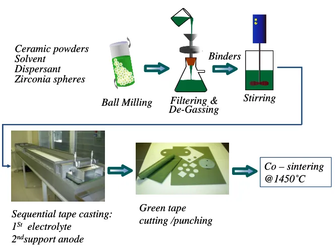
1.6 PRODUCTION OF ANODE SUPPORTED SOFC BY TAPE CASTING ... 55
SECTION 2 ... 59
GENERAL CONSIDERATIONS... 61
CHAPTER 2 ... 63
EXPERIMENTAL PROCEDURE ... 63
2.1 TAPE CASTING TECHNOLOGY FOR ANODE AND ELECTROLYTE PRODUCTION.... 65
2.2 SCREEN PRINTING TECHNOLOGY FOR CATHODE PRODUCTION ... 67
2.3 THERMOGRAVIMETRIC ANALYSIS ... 68
2.4 REDOX TESTS ... 69
2.5 ELECTROCHEMICAL TESTS ... 69
2.6 ELECTRICAL IMPEDANCE SPECTROSCOPY (EIS) ... 71
2.7 CURVATURE ANALYSIS UPON REDOX CYCLES ... 73
2.8 BIAXIAL FLEXURE ANALYSIS ... 75
2.9 OTHER ANALYSES ... 79
RESULTS AND DISCUSSION ... 81
CHAPTER 3 ... 83
ANODES WITH FUGITIVE MATERIALS ... 83
3.1 INTRODUCTION ... 85
3.2 PU-FOAM ... 87
3.3 ANODE AND HALF CELLS WITH PEMA-CO-MMA ... 88
3.3.1 INTRODUCTION ... 88
3.3.2 EXPERIMENTAL ... 88
3.3.3 RESULTS AND DISCUSSION ... 89
3.4 ANODE WITH ADDITION OF PMMA ... 96
3.4.2 RESULTS AND DISCUSSION ... 97
3.4.3 CONCLUSIONS ... 99
3.5 ANODE WITH ADDITION OF GRAPHITE ... 100
3.5.1 EXPERIMENTAL ... 100
3.5.2 RESULTS AND DISCUSSION ... 101
3.5.3 CONCLUSIONS ... 104
CHAPTER 4 ... 107
ANODE AND HALF CELLS PRODUCED BY ADDING CUSTOMISED CERAMIC PARTICLES ... 107
4.1 INTRODUCTION ... 109
4.2 EXPERIMENTAL ... 109
4.3 RESULTS AND DISCUSSION ... 110
4.4 CONCLUSIONS ... 120
CHAPTER 5 ... 123
ANODIC POWDERS AND HALF CELLS WITH DOPANT ELEMENTS ... 123
5.1 STUDIES OF THE REDOX KINETIC OF THE DOPED POWDERS ... 125
5.1.1 EXPERIMENTALS ... 125
5.1.2 RESULTS AND DISCUSSION ... 126
5.1.3 CONCLUSIONS ... 140
5.2 DEFORMATION OF UNCONSTRAINED HALF CELL WITH DOPED ANODE ... 141
5.2.1 EXPERIMENTAL ... 141
5.2.2 RESULTS AND DISCUSSION ... 142
5.2.3 CONCLUSIONS ... 151
CONCLUSIONS ... 153
APPENDIX ... 157
1 In the last decade the increase in energy demand, the awareness of limited availability of fossil fuels and the need to reduce green house gases emission impelled governments and research institutions to focus on the study of renewable energy sources such as solar, wind and biomass derived energy and on the increase in the energy production devices efficiency.
Within such scenario a relevant contribution is given by fuel cells technologies as advanced power generation system. Fuel cells are high efficiency devices and comply with the request of environmental friendly source of energy. They convert directly fuel energy into power and heat by electrochemical reactions without the need for combustion as intermediate step. The possibility to use Hydrogen makes fuel cells virtually zero-emission devices being water the only reaction product; nevertheless, also the use of hydrocarbons as fuel reduces considerable CO2 emissions.
Among the different systems, solid oxide fuel cells (SOFCs) operate at high temperatures (650-1000°C) and allow to achieve the highest electrical efficiency, from 45 to 60% for common fuels, values not attainable by traditional electrical power generation methods, and up to 70% in combination with a gas turbine for Hybrid Power System generation, with an overall electrical and thermal efficiency higher than 90%.
Moreover, such technology presents many advantages such as the possibility to be fed with different fuels, the absence of moving parts, modularity and limited emissions. These characteristics make SOFC suitable for application in the distributed generation market. Despite all the mentioned advantages, SOFCs show problems that make these devices not suitable for the production on industrial scale yet. In particular they present low reliability and are not competitive with traditional powers sources.
2
components; for instance they have to show similar thermal expansion coefficients, to be stable at high temperatures and during thermal transients.
Due to the high working temperature, stack components are necessarily subjected to degradation phenomena, which reduce their long term reliability. Among them, poisoning of cathode by Chromium evaporation from metallic interconnects, chemical interactions between glass–ceramic sealants and ferritic steel interconnects, anode poisoning caused by carbon or sulphur deposition, reduction of electrical conductivity are worthy of mention. Furthermore, various cycling conditions such as thermal cycle, redox cycle, and load cycle affect stability of SOFCs. All these degradation phenomena must be minimized in order to increase SOFC reliability. All these issues are object of intense research.
The research work of the present thesis has been focused on the increase of redox stability of anode supported cells, which is considered one of the key point to improve stack reliability.
The state of the art materials for the anode is Ni/YSZ cermet due to its high performance. Nevertheless, this cermet is prone to severe degradation upon redox cycling.
Due to the high operating temperatures, Nickel particles tend to coalesce and coarsen. Fuel supply interruptions, over-potentials and leakages can cause the re-oxidation of Ni to NiO with a consequent volumetric expansion that can generate internal stresses and lead to cracks formation within the YSZ network and the electrolyte resulting in cell failure. Different approaches can be taken in account in order to minimize redox instability.
In order to study redox phenomena and produce redox stable cells many aspects related to the modification of anodic microstructure were analyzed. Among these, one of the most promising method is to modify the anode microstructure by increasing its porosity.
The present thesis is divided in two parts. In the first section the theoretical background of fuel cells, specifically SOFCs, is reported. A particular attention is dedicated to describe redox phenomenon and the state of the art of the research in this field.
3 and by adding different pore formers and doping elements. A detailed study of the effects on redox stability of the microstructure modifications induced by the addition of each of the aforesaid substances is described.
Part of the experiments of this work, in particular electrochemical characterizations, have been carried out at SOFCpower Srl laboratories in Mezzolombardo (TN), an Italian leading company manufacturing cells and systems based on a proprietary SOFC technology
C
HAPTER
1
9
1.1
F
UEL
C
ELLS
Fuel cells are electrochemical devices that directly convert chemical energy into electrical energy and heat at high efficiency. As for the working principle, fuel cells can be assimilated to a battery; while the latter needs to stop for recharge, fuel cells operate continuously since a fuel and an oxidant are constantly fed.
This technology is well known, thanks to the initial contributions of many scientists such as Grove and Nernst in the first half of nineteenth century [1, 2]. The lack of adequate materials and investigation techniques along with high costs limited the use of fuel cells as power generation devices. Only in the last decades, the increase in the energy demand and of the costs of the traditional fuels, the need of alternative and renewable energy sources and the developments in material science have brought a new impulse to the research into the fuel cells field.
The most valuable feature of fuel cells is the possibility to work with high conversion efficiencies. Indeed, in a traditional power cycle, i.e. steam power plants and internal combustion engines, electrical energy is obtained by transforming chemical energy into heat which is subsequently converted into power. The irreversibility of this multistep process limits the electrical efficiency as for the Carnot’s principle. Moreover, the presence of mechanical rotating components further decreases the efficiency of traditional systems and increases maintenance costs.
Fuel cells are not subjected to such limitations because electricity is produced in a single step through an electrochemical reaction [1].
10
and polluting by-products of fuels combustion such as fine particulates and nitrogen oxides, making fuel cells a viable environmental friendly technology [3].
The fuel cells power systems contain different components that, in the order, are [4]: 1. Unit cells where the electrochemical reaction take place. A unit cell is constituted by
two electrodes: anode and cathode separated by the electrolyte.
2. Stacks, where unit cells are modularly combined by electrical connections in order to achieve the voltage and power output level necessary for the applications.
3. Balance of plant (BOP) that are auxiliary components including a fuel processor, if needed, thermal management, and electric power conditioning among other additional and interface functions (pumps, blowers, control valves, pressure regulators, cooling system, are some example).
Different types of fuel cells have been developed so far [5-7], each presenting specific advantages and drawbacks for different applications.
Fuel cells can be classified considering the type of used electrolyte (that determines the kind of chemical reactions that occur within the cell, the operative temperature, the kind of catalyst, the necessary fuel, and other attributes), or considering the fuel that they can process or in term of the working temperature range. For all of them the oxidant is air or pure oxygen.
11
Fig. 1.1: Summary of fuel cells types [6].
Low temperature fuel cells use only H2 and are generally classified as:
Alkaline fuel cells (AFC): the electrolyte is a solution of potassium hydroxide in water. They can use a variety of non-precious metals such as catalyst at the anode and cathode. High-temperature AFCs work at temperatures between 100°C and 250°C. Nevertheless, newer AFC designs operate at lower temperatures of roughly 23°C to 70°C. They have an efficiency of 50-60%.
25-12
30%. A third class of PEFC that works at high temperatures is HT-PEFC which can use H2 or CO as fuels at 120-180°C and reach an efficiency up to 40-50%.
Phosphoric Acid Fuel Cells (PAFC): this kind of fuel cell uses liquid phosphoric acid for the electrolyte; the acid is contained in a Teflon-bonded silicon carbide matrix, and the electrodes are made of porous carbon containing a Platinum catalyst. The operative temperature is about 200°C with an efficiency of 40-45%.
The high temperature fuel cells can operate with different fuels other than H2 such as CO,
natural gas, and hydrocarbon fuels:
Solid Oxide Fuel Cells (SOFC): the electrolyte is a dense solid ceramic material usually yttria stabilized zirconia (YSZ); typically, the anode is a Ni-ZrO2 cermet and
the cathode is Sr-doped LaMnO3. The operating temperature ranges between 700 and
1000°C, whereas the low temperature LT-SOFCs work at 500-650°C. SOFCs have an efficiency of 50-60%.
Molten Carbonate Fuel Cells (MCFC): the electrolyte is usually a combination of alkali carbonates (lithium, sodium and potassium carbonate), which is retained in a chemically inert porous ceramic matrix of LiAlO2. At the operating temperatures
(600-700°C) highly conductive molten salt is formed by alkali carbonates and the ionic conduction is supplied by carbonate ions (CO32-). Ni and nickel oxide are used as
anode and cathode electrodes, respectively. The efficiency of the MCFCs is around 50-55% [8, 9].
By a comparison of the different kind of fuel cells, from the high to the low temperature fuel cells, one can observe a decrease of the efficiency, higher sensitivity to contaminant elements and increased complexity of fuel processing [6].
13 Therefore, carbon monoxide does not represent a harmful substance for the anode, and it can be directly fed as fuel. The materials used in SOFCs are not too expensive. Thin-electrolyte planar SOFC unit cells have been demonstrated to be capable of power densities close to those achieved by PEFC. Moreover, high-temperature MCFCs and SOFCs are ideal candidates for fuel cell/gas turbine hybrid systems thanks to the possibility to use the discarded thermal energy and the energy from the combustion of residual fuel to drive gas turbine (GT).
Currently, it is possible to observe a rapidly growing trend in the application of fuel cells in different industrial fields. The applications of fuel cells can generally be divided into portable, transport and stationary purposes, including combined heat and power systems (CHP). However, the viable application varies according to the type of used fuel cells:
− AFCs were the first type of FCs widely used in U.S. space program to produce electrical energy and water on-board spacecrafts, e.g. Apollo or Shuttle;
− PEMFC are found in vehicles and portable applications, and for power CHP systems;
− DMFC are suitable for low power portable electronic systems;
− PAFC are used for a large number of 200 kW CHP systems;
− MCFC are suitable for medium to large scale CHP systems, up to MW capacity; they are used in industrial and military applications;
− SOFC are appropriate for all size of CHP systems, 2 kW to multi MW, automotive industries, and portable devices; they can be used for hybrid/GT cycles.
Apart from the previously mentioned high efficiency, fuel cells provide many other advantages over traditional energy conversion systems: modularity, fuel adaptability, and very low levels of NOx and SOx emissions. Quiet, vibration free operation of FC also
eliminates noise usually associated with conventional power generation systems.
14
requirement of appropriate materials or manufacturing routes that would permit the cost of electricity per kWh to compete with the existing technology.
15
1.2
S
OLID
O
XIDE
F
UEL
C
ELL
(SOFC)
The topic of the present thesis is the study of instability to the redox cycles for anode supported solid oxide fuel cells; therefore, in this section SOFC devices will be described in detail.
SOFCs operate at temperatures ranging from 550°C to 1000°C allowing to reach high electrical efficiencies (up to 60%); moreover, the possibility to feed them with different fuels, as Hydrogen, carbon monoxide and hydrocarbons, and their ease of production are some advantages that explain the high interest of researchers and industries on this technology with respect to the other types of fuel cells. On the other hand, it has to be mentioned that, the high operating temperatures are critical for the long time reliability of SOFCs, as materials degradation rate increases.
There are different types of SOFC design, basically tubular and planar, which differ in the single cells design and arrangement, interconnect materials and gas flow. Each of these two designs has a number of interesting variants: for example, planar SOFC may be in the form of circular disc fed with fuel from the central axis, or it may be in the form of square plate fed from the sides.
Tubular cells can be distinguished in two broad categories: cells with a large
diameter, >15 mm, and cells with a diameter lower than 5 mm, usually named microtubular cells [10].
16
In the first cell the tube was made of calcia-stabilized zirconia with the walls as thin as possible considering its support function.
In the most recent production the porous supported tube has been replaced by a doped LaMnO3 tube having the function of cathode (air-electrode supported cell) onto which the
other cell components are deposited.
17 The result of this substitution was a decrease of the inherent impedance to air flow toward the cathode. Siemens Westinghouse Power Corporation tubular SOFC design is reported in figure 1.2; the cells are nominally 2.2 cm in diameter and 150 cm in active length with one closed end. Air is supplied to the cell interior using an air delivery tube and fuel is delivered to the cell exterior [12, 13].
Power produced is proportional to the active surface area of the cells. Their operating temperature is about 1000°C; at such temperature and under atmospheric pressure, single tubular SOFC generates power of up to 210 W DC (direct current).
Each cell attains (at open circuit) a potential of about 1 V; therefore, in order to reach a voltage suitable for applications, cells are connected in series. The materials commonly used for the components are YSZ for the electrolyte and Nickel/zirconia cermet, bonded to the electrolyte, for the anode. The cathode, fabricated as an extruded porous tube, is made of Lanthanum manganite, and the cathode interconnection consists of thin strip of Lanthanum chromite.
The tubular cell design offers different advantages with respect to planar ones; for instance, sealing problem is eliminated by inserting an air feeder tube down the cell tube. Tubular cells are more stable against mechanical and thermal stresses than planar cells. Nevertheless, modern technologies (tape casting, screen printing, vapour deposition. plasma spraying, wet spraying and others) allow lower costs for the fabrication of planar cells.
Microtubular cells have been developed since early 1990s when YSZ tubes with
18
supported microtubular cells are produced allowing to increase the power output of these systems [16, 17].
Planar cells can be produced with different configurations: electrolyte supported
(ESC), cathode supported (CSC), anode supported (ASC) and metal supported (MSC) cells [18-20].
For cells with thin YSZ electrolytes (5-20 µm) as for anode supported cells (ASC), the operative temperature can be reduced (< 800°C). Operating at this temperature condition allows a wider choice of materials (especially low-cost metallic materials for the interconnect), longer lifetime, reduced thermal stresses, improved reliability, and potentially reduced cell cost [21]. The main disadvantages are potential slow electrode reaction kinetics (and therefore high polarisations) and the reduced thermal energy that can be extracted from the hot exhaust stream by a turbine or a heat exchanger. ASC configuration is preferred to the other ones due to the low ohmic losses associated to the thin electrolyte.
In the following section it will be referred to the ASC with planar geometry being it the configuration considered in the present research work.
19
Fig. 1.3: Stack cells design for a planar anode supported SOFC.
A functional stack is constituted by different elements with specific properties. A sketch of anode supported SOFC in planar configuration is reported in figure 1.3. The cell is composed by two porous electrodes, anode and cathode, separated by a dense Oxygen ion-conducting electrolyte. Every cell is connected in series with another cell by an interconnect. A large number of units can be repeated in order to produce the desired power. Then a sealing system of anode and cathode compartment is needed in order to avoid the mixing and combustion of fuel and air.
20
• In the stack ohmic losses need to be minimized in order to show good electrical performance. This can be obtained by considering the current path in the components to be as short as possible; there must be good electrical contact and sufficient contact area between the components. The current collector must also be designed to facilitate current distribution and flow in the stack.
• The design must provide for minimal polarisation losses so that high electrochemical performance is obtained. Therefore, any gas or cross-leakage and electrical short circuit must be avoided. Fuel and oxidant must be distributed uniformly not only across the area of each cell but also to each cell of the stack. Moreover, in order to decrease mass transport limitations, the gases must be able to rapidly reach the reaction sites. • Stacks need to possess thermal compliance. In other words, the design must permit the
highest possible temperature gradient across the stack and, in addition, must provide for stack cooling and uniform temperature distribution during operation.
• Stacks require mechanical and structural integrity. Planar SOFC stack must be designed in order to have adequate mechanical strength for assembly and handling. Therefore, mechanical and thermal stresses must be kept to minimum to prevent cracking, delamination or detachment of the components under variable operating conditions (for instance, normal operating temperature gradients, off-design temperature gradients, thermal shock conditions such as sudden power change and cold start-up, and mechanical loading expected during installation).
22
1.3
SOFC
O
PERATION
P
RINCIPLE
1.3.1
THERMODYNAMIC CONSIDERATIONS
Different fuels such as Hydrogen, carbon monoxide, natural gas and other hydrocarbons can be used in SOFCs.
The overall electrochemical reaction when Hydrogen is used is the oxidation of Hydrogen by Oxygen into water.
The Oxygen is adsorbed within the cathode and it is reduced producing Oxygen anion:
− −
→
+
2 22
2
1
O
e
O
(1.1)The Oxygen anions are transported through the electrolyte into the anode where they react with the adsorbed Hydrogen:
−
−
→
+
+
O
H
O
e
H
22
2
2 (1.2)
The overall reaction in the cell is the addition of the two previous semi-reactions:
( )g
O
( )gH
O
( )gH
2 2 22
1
=
23 The maximum electrical work (Wel) obtainable in a fuel cell operating at constant
temperature and pressure is given by the change in Gibbs free energy (∆G) of the electrochemical reaction:
eq
el
G
nFE
W
=
∆
=
−
(1.4)where Eeq is the Nernst potential or theoretical open circuit voltage (OCV) that can be
measured when there is no current in the circuit; n is the number of electrons exchanged in the overall reaction and F is the Faraday constant (96487 C/molel).
If the reactants and products of the cell reaction are in their standard states at the temperature of the transformation, the Gibbs free energy change is given by the standard value (∆G0) and by the reaction equilibrium constant (Keq),
( )
+
∆
=
+
∆
=
∆
2 1 0 0 2 2 2ln
ln
O H O H eqP
P
P
RT
G
K
RT
G
G
(1.5)The equilibrium constant for SOFCs typical operation conditions can be written as the ratio between partial pressure of products and reactants, instead of using the related fugacities, since in the usual operative conditions of SOFCs the gases behave as ideal.
Since:
0 0
eq
nFE
G
=
−
∆
(1.6)24
+
=
O H O H eq eqP
P
P
nF
RT
E
E
2 2 2 2 1 0ln
(1.7)Nernst equation provides a relationship between the ideal standard potential (
E
eq0 ) for thecell reaction and the ideal equilibrium potential (Eeq) at the partial pressures of reactants and products. It can be observed that the cell potential increases with an increase in the partial pressure (concentration) of reactants and a decrease in the partial pressure of products.
The standard Gibbs free energy for the reaction (Eq. 1.3) is ∆G0=-228.59 kJ/mol [10], to
whom corresponds
E
eq0 =1.18 V.The ideal standard potential depends on the fuel used in the cells. For instance, if SOFCs are fed with CO or methane the overall reactions are:
( )g
O
( )gCO
( )gCO
2 22
1
=
+
(1.8)( )g
O
( )gCO
( )gH
O
( )gCH
4+
2
2=
2+
2
2 (1.9)and the corresponding ideal standard potential are
E
eq0 =1.33 V andE
eq0 =1.04 V,respectively.
In real operation conditions, the fuel cell potential is lower than the theoretical one due to irreversibility losses associated with the current production.
25
Fig. 1.4: Ideal Current – Voltage plot characteristic for fuel cell.
In such plot it is possible to see that the measured OCV is lower than the theoretical one. At low current densities a rapid fall of potential is observed, then as the current density increases the voltage decreases slowly with a quite linear trend. In the last part of the curve, at very high current densities, a sharp voltage reduction occurs. This behaviour can be explained considering that there are different types of polarization losses which are dominant in different range of current density:
Fuel crossover and internal currents
Activation polarization (ηact) Ohmic polarization (ηohm)
Mass transfer losses or concentration polarization (ηconc)
26
conc ohm act eq
E
V
=
−
η
−
η
−
η
(1.10)Fuel crossover and internal currents
As mentioned in the previous paragraphs the ideal electrolyte should be exclusively ionic conductor and impervious to gases. In a real cell some fuel diffusion across the electrolyte and electron conduction can occur. The passage of the fuel from the anodic to the cathodic compartment results in its combustion without contributing to the electrical power generation. This small amount of wasted fuel is termed fuel crossover. On the other hand, a finite electrical resistance of the electrolyte causes an internal current from the anode to the cathode without passing through the external circuit. These two phenomena occur also at open circuit and explain the lower actual OCV in comparison to the ideal one. This kind of losses is more critical in fuel cells working at low temperatures (PEM), while are less important at high temperatures where the real OCV is approaching Nernst potential.
Activation polarization (ηact)
An electrochemical reaction involves charge transfer at the electrodes interface which results in a current density. The latter is proportional to the reaction rate and determines a loss in cell voltage called activation polarization or overpotential.
In other words the activation polarization is the energetic barrier that is necessary to overcome in order to realise the reaction and it is correlated to the reaction rate. More in detail the activation polarization is correlated to the slower stage of the reaction that is realized at the anode/cathode compartment.
27 from the surfaces and each of them are thermal activated; so ηact is correlated with many
parameters (i.e. material properties, microstructure, atmosphere, and temperature). Butler-Volmer equation correlates the current density with the overpotential:
(
)
−
−
−
=
RT
nF
RT
nF
i
i
β
η
act1
β
η
actexp
exp
0 (1.11)
where β is the transfer coefficient, ranging from 0 to1 and depending on the electrode material and reaction involved; i0 is the exchange current density which represents the electron exchange across the electrode/electrolyte interface when the current density i is zero.
The contribution of activation polarization in the cell voltage loss is more evident at low current density.
In order to decrease this contributes it is possible to increase the reaction rate in both the electrodes, which is influenced by many factors (temperature, active area and activity of the electrodes); in fact it is possible to decrease the polarization losses by increasing the operative temperature, and/or the active area of the electrodes; moreover, by using an appropriate catalyst, it is possible to enhance the activity of the electrodes.
Ohmic polarization (ηohm)
Ohmic polarization is the result of losses due to the intrinsic electrical resistance of the electrodes and electrolyte materials. There is a linear relation between this polarization and the current density:
(
el
e cl
c al
aR
contact)
i
ohm
=
ρ
+
ρ
+
ρ
+
28
where ρe, ρc, and ρa are respectively electrolyte, cathode, and anode resistivities and le, lc, and la are respectively electrolyte, cathode, and anode thicknesses, and Rcontact is any possible contact resistance. The ohmic polarization contribution to total cell losses is important in the intermediate current densities range as shown in figure 1.4.
In most SOFCs, the main contribution to ηohm is from the electrolyte; for instance, the ionic resistivity of the electrolyte state of the art material (YSZ) at 800°C is about 50 Ωcm. This can explain the superior performances behaviour of the ASCs, where the electrolyte is thin (less than 20µm), compared with the ESCs.
The ohmic resistance normalized by the active cell area is the Area Specific Resistance (ASR). The ASR is a function of cell design, material choice, manufacturing technique, and, operating conditions because material properties change with temperature. The ASR is a key performance parameter, especially in high-temperature fuel cells, where the ohmic losses often dominate the overall polarization of the cell.
Mass transfer losses or concentration polarization (ηconc)
At high current densities the concentration polarization becomes more relevant. Indeed in this current range the reaction control passes from the chemical stage to the mass transfer stage. In other words, the limiting step of the overall reaction is the diffusion of the reactants from the bulk of the gases to the electrodes interface and/or the counter diffusion of the products.
29
1.4
SOFC
C
OMPONENTS AND
M
ATERIALS
The core of a SOFC stack is the cell. As mentioned a cell is constituted by different components: two electrodes (cathode and anode) and one electrolyte. Considering the planar ASC, each cell is electrically connected to the others through metallic interconnects. Due to the high operating temperature, and to the all-solid state nature of the components, the coefficient of thermal expansion of each material composing the stack must be as close as possible, in order to avoid mechanical fracture and material delamination due to thermal stresses that develop during thermal cycling of the cells. Moreover, they require to be stable at high temperatures (they operate at 800-1000°C) and to be produced with cost-effective materials.
The characteristic and the properties that the stack elements must possess are briefly described in the following, focusing on the planar anode supported cells configuration, being the kind of cells investigated in the present work.
30
Fig. 1.5: Schematic picture showing the operating principle of SOFC.
1.4.1
CATHODE
The cathode is kept in oxidising atmosphere during operation. The molecular Oxygen diffuses through the cathode and reduces at the interface with the electrolyte into Oxygen anions. For this reason the cathode materials need to be stable in this environment, have a high ionic and electronic conductivity and catalyze the dissociation of Oxygen. They must have a high porosity in order to let the Oxygen to reach easily the electrolyte surface where there are the active reaction sites, known as triple phase boundary (TBP). The active sites concentration should be high in order to ensure good cathode performance. Other important requirements that a cathode should fulfil are a good adhesion with the electrolyte interface and chemical compatibility with adjacent cell components [23,24].
31 Usually the cathode is produced by using ceramic materials, typically Lanthanum manganites. They have a perovskite-structure oxide that exhibits p-type electronic conductivity. In order to increase their electronic conductivity they can be doped with lower-valence cations, such as Strontium, Calcium, Barium, Nickel or Magnesium, or by other alkaline- or rare-earth cations [25, 26]. The state of art for cathode materials when YSZ is used as electrolyte are Strontium doped LaMnO3 (LSM) and Strontium doped
Lanthanum cobaltites (LSC) for their high electrical conductivity as well as for thermal expansion and chemical properties compatible with other SOFC component materials [27]. LSM applications are limited to temperatures higher than 800°C; instead at lower temperatures LSC are the preferred cathode materials due to their good electrical conductivity in this range of temperatures [28, 29]. Many alternative and promising materials based on rare earths perovskites are currently under development [30].
1.4.2
ELECTROLYTE
32
to avoid cracks or pores formation either during manufacture or in the course of long-term operation.
Fluorite-structured oxide materials such as yttria stabilized zirconia (YSZ), rare earths doped ceria, and rare earths doped Bismuth oxide have been widely investigated as electrolyte materials for solid oxide fuel cells [23, 31]. Among these materials YSZ has been successfully employed, and currently is the state of art as electrolyte material. It can be used either as 3YSZ, i.e. ZrO2 doped with 3 mol% Y2O3 (TZP) or 8YSZ, i.e. ZrO2 doped
with 8 mol% Y2O3 (CSZ). Although the oxide ion conductivity of 3YSZ is significantly
lower than that of 8YSZ, this material is advantageous because of its outstanding mechanical stability.
Yttrium oxide (Y2O3) is introduced as dopant into the zirconia for two reasons:
It stabilizes the high temperature cubic phase that posses the highest ionic conductivity between the different crystal phases. In fact the pure zirconia exists in three crystal phases at different temperatures. At very high temperatures (>2370°C) the material has a cubic structure (c). At intermediate temperatures (1170 to 2370°C) it has a tetragonal phase (t). At low temperatures (below 1170°C) the material transforms to the monoclinic structure (m). In nature these transformations are martensitic and the transformation from tetragonal to monoclinic is rapid (by cooling) and is accompanied by volume increase that causes extensive cracking in the sintered material. This behaviour leads to dramatic failure of fabricated components during cooling and makes pure zirconia useless for any structural or mechanical application. Instead the use of Y2O3 or other oxides such as CaO, MgO,
Sc2O3 and rare earth oxides as dopant can stabilise the monoclinic structure in the cubic or
tetragonal form.
It increases the oxide ionic conductivity introducing Oxygen vacancies. For instance one mole of Oxygen vacancy is created for each mole of Y2O3 dopant, as can be observed
by the defect reaction written in the Kroger–Vink notation:
• •
+
+
→
O x O Zr ZrOV
O
Y
O
Y
2 32
'3
33 where
Y
Zr' is the lower valence cation,O
Ox is the oxygen ion on normal sites andV
O••is the Oxygen vacancy [32].Moreover zirconia has good thermal and mechanical shock resistance when doped with yttria (Y2O3), scandia (Sc2O3), samaria (Sm2O3) and magnesia (MgO).
The Oxygen ionic conductivity behaviour of electrolyte materials against the temperature can be observed by the graphic reported in figure 1.6, where it is possible to see that different materials such as Ce0.9Gd0.1O1.95 and Bi2V0.9Cu0.1O5.35 posses at lower
temperature higher conductivity than (ZrO2)0.9(Y2O3)0.1. But this condition is not sufficient
to choose them instead the doped zirconia as electrolyte material; in fact, for instance, Bi2V0.9Cu0.1O5.35 is not stable in the reducing environment of the anodic compartment of a
fuel cell. It has to be also stressed that, among the candidate materials, yittria stabilized zirconia is a relatively cheap base material.
In addition it is sufficient to produce YSZ electrolytes with a thickness lower than 15 µm to have a specific ionic conductivity greater than 10-2 Scm-1 at 700°C that allows to
34
Fig 1.6: Oxygen ion conductivity vs. reciprocal temperature for different doped oxides for SOFC electrolyte [6].
Even if YSZ based electrolytes represent the state of the art materials, ceria based materials seem to be promising candidates for electrolyte production and are object of an intense research [33].
Pure ceria has a fluorite-type structure over wide ranges of temperature and Oxygen partial pressure. The electronic defects concentration and conductivity are directly related to the degree of non-stoichiometry that increases with the temperature and decreases with Oxygen partial pressure. Doping of ceria with a number of oxides such as CaO, Sm2O3,
Gd2O3, Yb2O3, Y2O3, La2O3, increases the concentration of Oxygen-ion vacancies and the
material exhibits high ionic conductivity.
On the other hand, for instance, Gd doped CeO2 (GCO) become mixed conductor in
35 Other alternative materials are the oxide having ABO3 perovskite structure; this
structure is extremely amenable to tailoring via doping on both the A and B cation sites. A large variety and concentration of dopants can be accommodated in a wide range of host compounds. Introduction of divalent dopant ions, in general Strontium and Magnesium, into the Lanthanum and Gallium sites (LSGM: (La,Sr)(Ga,Mg)O3), respectively, of
Lanthanum gallate LaGaO3 produces a material with a high concentration of mobile
Oxygen vacancies and thus high Oxygen ion conductivity. On the other hand, they do not show long term stability due to Ga evaporation in a reducing atmosphere. Moreover, Lanthanum gallate undergoes deterioration for its reactivity with Nickel, the typical SOFC anode electrocatalyst [30-35]. In addition, the use of LSGM as electrolyte shows problems due to the low mechanical stability and the high costs of Gallium.
So far zirconia based oxides remain the best and more cost effective electrolyte materials. Sc-doped ZrO2 electrolytes are the most promising alternative as this dopant material
allows to increase the ionic conductivity significantly for reduced operating temperatures so far. On the other hand the low quality of ScSZ-powders available, and the high cost of Scandium restricted its use.
A further consideration is that the electrolyte needs to show a high strength and toughness especially in planar configuration. Several fuel cell developers add a small quantity of alumina to YSZ based electrolytes to enhance the mechanical strength [31, 36-39].
1.4.3
ANODE
The electrochemical oxidation of the fuel is realized into the anodic compartment. If Hydrogen is used as fuel the oxidation products are water vapour and electron as evidenced in Eq. 1.13:
−
−
→
+
+
O
H
O
e
H
g2
2
v4
2
2 ( )2 ) (
36
The porous anode in SOFCs offers the sites for the fuel gas to react with the Oxygen ions delivered by the electrolyte, within a structure which also facilitates the necessary charge neutralisation by its electronic conductivity.
In order to have a SOFC with high performance also the anode material must exhibit different properties [23].
The anode has to be chemically stable in reducing atmosphere, show high electrochemical/catalytic activity, necessary for the kinetic of the reaction, be sufficiently porous to permit efficient transport of the fuel to the active sites and to remove products such as water. For the anode supported cells (ASC), it needs to be thick enough and show a good mechanical strength; for the latter a compromise with the porosity is necessary. Moreover, the anode must be chemically compatible with the electrolyte and with the interconnect materials without interdiffusion between adjacent layers; high wettability with respect to the electrolyte substrate is extremely important in order to have a good adhesion between the layers and avoid delamination during operations. Anode necessitates to match the shrinkage during sintering and the thermal expansion coefficient with the neighbouring components in order to minimise stresses caused by temperature variations during operation, start-up and shut-down.
37 The performances of a SOFC depend strongly from the anode microstructure and it is very important to understand the phenomena involved in the anode during operation. The electrochemical reaction takes place only in a particular zone namely three-phase boundary (TPB). In this zone, Oxygen ions accessible from the electrolyte reacting with the fuel can discharge electrons to the conducting anode. This requires a gas phase for the fuel access, an electrolyte phase for oxide ion entry and a metal phase for electrons output. The anodic microstructure must provide an active volumetric reaction region in three dimensions homogeneously distributed through the anode in order to have good efficiency and low losses at operation conditions. The absence of one of this phase due to the breakdown in connectivity has as consequence that the reaction cannot occur being not catalyzed. In addition, a site will not contribute to the performance of the cell if the gas cannot reach the site or the electrons cannot be removed from the site.
Consequently, anodes materials selection and production techniques are very important in determining a structure with high TPB concentration and stable during cell operation life. Considering the polarisation losses in the anodic compartment it can be observed that:
Activation polarization is related to the charge transfer processes, as before explained, and depends on the electrocatalytic activity of the anode and then on the extent of the triple-phase boundaries zone (electrode, electrolyte, and fuel).
Ohmic resistance that includes: (i) the internal resistance, related to the resistance to the transport of electrons within the anode and therefore to the electronic resistivity and thickness of anode; (ii) the contact resistance due to low adhesion between anode and electrolyte layer.
Concentration polarization depends on the transport of gaseous species through the porous anode and, thus, on the anode microstructure, or, in other words, on the volume percent porosity, the pore size, and the tortuosity factor.
38
used. For instance, graphite is electrochemically corroded so it cannot be used; Platinum during operative work spalls off probably for the water vapour development at the metal - oxide interface; corrosion of Iron is observed when the partial pressure of oxidation products in the anode compartment exceeds a critical value [9, 40].
The use of the Nickel evidenced significant thermal expansion mismatch with YSZ electrolyte; the metal aggregates by grain growth at high temperatures, with consequent decreasing of anode porosity and three-phase boundaries required for cell operation [9, 41]. The anode material that fulfils great part, but not all, of the previous requirements is, until now, a mixture of ceramic and metallic materials, the porous Ni/YSZ cermet.
Use NiO and YSZ powders as starter materials for anode production present different advantages instead of use pure Nickel. No reaction occurs between the anode and electrolyte being Nickel and YSZ not miscible even at high temperatures. Electronic conductivity and catalytic activity are provided by Ni in the cermet anode; instead, the rigid ceramic YSZ structure constitutes the network where the Nickel is dispersed, and gives mechanical resistance to the anode, especially for the ASC; moreover, YSZ lowers the activation polarization since it serves as a pathway for Oxygen ions migration and therefore extends the triple phase boundary region inside the anode (being usually limited to the interface between the electrolyte and other anode materials); in addition YSZ adjusts the coefficient of thermal expansion (CTE) close to that of YSZ electrolyte.
A particular and important issue in the Nickel based anode is related to the fact that, during operation at high temperature, and under electric load Ni tends to sinter, coarsen and agglomerate. These in tumble give: (i) a decrease of anodic porosity and of the active sites available for oxidation (having a negative effect on the gas transport and reaction kinetics) that determines an overall efficiency decrease of the fuel cell by increasing the polarization losses; (ii) an increase in the redox instability.
39 It is worth noting that the NiO and YSZ powders are relatively cheap in comparison with other anodic raw materials.
In the ASC configuration the sintered anode is constituted by a thick YSZ network where NiO is distributed. At the start up of the cell Nickel oxide is reduced with H2 in order
to have the activation of the catalysis sites for the H2 oxidation. The reduction of NiO into
Ni metallic (Eq. 1.14) is accompanied by a 40.9% Nickel phase volume reduction based on dense NiO [43] with consequent increase of the anode porosity.
A porosity of 30–40 vol% is necessary to supply the gas for the reaction and to remove the reaction products [44]:
( )g
Ni
H
O
( )vH
NiO
+
2=
+
2 (1.14)The amount of Nickel contained in the cermet influences the electrical conductivity of the anode. The percentage of Ni in the cermet is determined in order to assure the percolation threshold, this is the adequate amount of Nickel for continuity of the electron conduction. The S-shaped curve correlates the conductivity of the cermet as a function of Nickel content as reported in figure 1.7.
The quantity of Nickel in the anode has to be at least 30 vol% into the cermet, in order to ensure sufficient electronic conductivity. This concentration is the threshold value at which the conduction mechanism switches from ionic to electronic. Usually Nickel is found in concentrations of 40-60% in the anode cermet with a porosity of 20-40%, the latter to facilitate the mass transport of reactant and product gases [23].
40
Fig. 1.7: Variation of electrical conductivity measured at 1000°C as a function of Nickel concentration of Ni/YSZ cermet fired at different temperatures [45].
As reported by Zhu and Deevi [41], porosity, pore size, size distribution, and size of raw powders as well as contiguity of each component influences the percolation threshold and, as consequence, also the Ni/YSZ cermet electrical behaviour; for instance, particle sizes of YSZ and of Nickel affect the electrical conductivity, that increases with an increase of the ratio of their size (dYSZ/dNi), for a fixed Ni amount and porosity. In order to have an anode showing high electrical conductivity, stable microstructure, as well as sufficient porosity, it is necessary an optimization of all processing variables since from the mixing of the selected raw materials, preparation, sintering temperature [46, 47]; moreover, the fuel composition and gas flow rates influence the FC overpotential [41].
41 anode the goal is a fine microstructure with as large a TBP as possible and connectivity in both Ni and YSZ phases. The activity depth of the functional anode is of the order of 5 to 10 µm and usually layers of 20 to 30 µm are used [48]. On the other hand this thin layer, due to its density, is more sensible to redox degradation.
As before mentioned, the Ni/YSZ cermet do not accomplish all the ideal anode properties; indeed it presents different disadvantages during the fuel cell operation such as:
(a) poor redox stability;
(b) Nickel agglomeration after prolonged operation; (c) low tolerance to Sulphur;
(d) carbon deposition when using hydrocarbons as fuel.
The last two issue are related to the use of the fuel. The degradation of cells due to redox instability is explained in depth in the following.
As mentioned before, the operating temperature of a SOFC is controlled by different thermal activated processes like the Oxygen ion conductivity of the solid electrolyte and different chemical and electrochemical reaction steps in the electrodes or at the electrode/electrolyte interfaces. A decrease in the operating temperature generally results in increased losses of the cells and a decreased power density at a constant efficiency. On the other hand, the long term stability of the system is improved and the system costs can be reduced by using cheaper metal alloys for interconnects and for external components. Moreover, if the device is used under pressure as SOFC/gas-turbine hybrid system the temperature is restrained.
42
1.4.4
INTERCONNECT
A single cell produces a potential lower than 1V. In order to increase the voltage output for practical applications it is necessary to pile-up different cells in a stack. In the case of planar cells, these are superimposed and the anode of one cell is separated from the cathode of another by an interconnect. The latter has two functions:
− Ensure the electrical connection between adjacent cells;
− Separate anodic and cathodic compartments of neighbouring cells.
Interconnects must comply with many requirements: high temperature oxidation and reduction resistance; stability under multiple chemical gas streams; high electrical conductivity and high density with closed porosity; in addition they necessitate a good thermal conductivity, phase stability over wide temperature range, need to be resistant to Sulphur poisoning, oxidation and carburization and moreover, for planar configurations, show strong and high creep resistances.
The most common interconnect material, for high temperature SOFCs, is alkali doped LaCrO3 (Lanthanum chromite), with the specific dopant (typically, Sr, Ca or Mg) and
concentration being selected to best match the thermal expansion of the other fuel cell components in the geometry of interest. The problem with the Lanthanum chromite is its difficult to process because of chromia evaporation at high temperatures, which leads to poor densification [35].
43 detrimental during long-term operation, and is prone to cracking and spalling [23]. Moreover, Chromium evaporation occurs at operation temperatures causing irreversible poisoning of cathode active sites [52].
Among the metallic interconnects the most used materials are ferritic steels because they are cheaper and easier to process then the other candidate alloys. Different efforts were undertaken to develop more suitable compositions, which led to the development of several special alloys. Currently Crofer22 APU (Krupp) is widely used.
To reduce the degradation of metallic interconnects, a protective coating is applied on their surfaces.
Usually the materials used for the coating are perovskites as Lanthanum Strontium manganite (LSM), or Lanthanum Strontium cobaltite (LSC). It was observed that the presence of Manganese leads to the formation of a Mn-Cr spinel having good conductivity, and the reduction of Chromium evaporation, thus improving the long term performances of the cells. In the last years Mn based spinels as Cobalt manganite (Co2MnO4) were
successfully applied as coating showing an important improvement in the cathode protection assuring a high conductivity to the interconnect [53, 54].
1.4.5
SEALING
44
Three type of sealing can be considered: rigid bonded seals, compressive seals, and compliant-bonded seals. Specifically, rigid-bonded seals are the most common and are usually made from glass or glass-ceramic materials [23]. This type of seal is attractive considering that their viscous/wetting behaviour facilitates hermetic sealing; they are cheap and easy to manufacture and apply and fulfil many of the key properties required for a sealing material; in addition, glass-ceramics can be designed to avoid viscous flow and uncontrolled progressive crystallization during operation.
45
1.5
SOFC
I
SSUES
This section deals with one of the problems related to an easy commercialization of SOFC. In fact, in spite of the great potentiality of solid oxide fuel cells (SOFCs) there are still several problems that need technological solution and make these devices still not available for a large scale use.
In this paragraph the redox instability of the planar anode supported SOFC is discussed in detail being one of the most relevant obstacles for the production of reliable SOFC systems. Considering that the aim of this work was to increase the tolerance to redox cycle a detailed description of the redox phenomenon is necessary.
1.5.1
REDOX INSTABILITY
Among SOFCs the anode supported configuration shows the best electrochemical performances due to the thick anode (range 100-1000 µm) constituted usually by a Ni/YSZ
cermet and a thin electrolyte (YSZ) (ranging between 6-20 µm) that minimizes the ohmic losses in comparison with the other cell configurations.
Indeed, Nickel is a good electronic conductor and an excellent electro-catalyst for the electrochemical Hydrogen oxidation; moreover the YSZ framework constitutes a good Oxygen ions conductor. In addition Ni/YSZ cermet has a high chemical stability in reducing atmosphere and has a good matching of thermal expansion coefficient (CTE) with YSZ electrolyte [13, 30, 41].
46
literature using anode-supported cell architecture, none report multiple redox cycles with no degradation due to microstructural modification of a Ni-YSZ anode [43].
During fuel cell operation the anode is in a reduced state, but for different reasons the anode can re-oxidize: for instance, discontinuous fuel supply, emergency stop, system shutdown without fuel, overpotentials or insufficient fuel permeation through the anode can determine undesired oxidation of the metal phase within the cermet, this being responsible for the phenomenon usually defined as redox instability.
A model of the microstructure evolution during reduction and subsequent oxidation was developed by T. Klemensø et al. [58]. The model is reported in figure 1.8 to better explain the microstructural modifications due to the redox phenomenon.
As sintered, the anodic microstructure appears with low porosity and NiO is uniformly distributed into the YSZ network, in order to guarantee the percolation (Fig. 1.8a).
47
Ni-agglomeration
(c) (d) Re-oxidation
In-situ activation (reduction) (b)
(a) As prepared (sintered)
Ni-agglomeration (c) Ni-agglomeration
(c) (d)(d) Re-oxidationRe-oxidation In-situ activation (reduction) (b) In-situ activation (reduction) (b)
(a) As prepared (sintered) (a) As prepared (sintered)
48
In the last years many investigation were developed by different research groups on the mechanism and characterization of the redox behaviour, but it is still far to solve the problem [61].
Klemensø and Mogensen improved later the proposed model of the process occurring during more redox cycles from the results obtained by direct current (DC) conductivity measurements and by thermo-gravimetric study of redox kinetics. They observed that the anode electrical properties depend on samples porosity; the decrease in the electronic conductivity reflects Ni coarsening and agglomeration. Oxide growth mode causes damages to the YSZ network but may also promote improved percolation of the Ni/NiO network until a critical porosity [62].
Different approaches were used to examine the redox phenomenon, in order to understand the kind of modifications necessary to overcome this issue. Ni-based anode specimens with apposite composition and having different shape such as discs, bars or powder were tested in order to investigate the effect of redox cycling.
For instance, D. Sarantaridis et al. [63] investigated the redox behaviour in order to determine the critical degree of oxidation for ASCs that leads to irreversible mechanical damage. To obtain these data they oxidised two different configuration cells: free-standing cells were oxidized in air and cells that were sealed at their periphery to the fuel plate were oxidized electrochemically. They observed that free-standing cells resulted in failure at a critical degree of oxidation of about 50%, instead the constrained cells were fully disrupted with a critical degree of oxidation of about 5%. Moreover, they gave an interpretation of mechanical failure and noticed that a non-uniform oxidation process have more catastrophic effects than an uniform one. They considered that peripheral tensile stresses can be generated if the oxidation is non-uniform and concentrated in the central part of the cell. This leads to a central zone of expansion that creates a radial compressive stress in the surrounding material and a tensile hoop (tangential) stress.
49 Wood and al. [43] in their paper reported a categorization of the possible solutions; they considered system solutions (such as purge gas or cell reversal, high temperature check valves and so on) and unit cell or material solutions. The former are expensive and need a deep evaluation on a number of criteria including effectiveness of solution, efficiency, amount of additional system equipment, safety and technical risk. The latter are less expensive since do not require special system power or control. Inside this category are considered: materials alternative to Ni/YSZ cermet anodes, microstructure modifications, changes in kinetic of reactions, improved sealing and lower stack operating temperatures.
Use of alternative materials
One possible solution to solve redox instability is the utilization of alternative anode materials to Ni/YSZ cermet and the choice of substances that are not as susceptible to oxidation, or better that do not posses relevant dimensional variation due to change of oxidative state.
The continuous search for alternative anode materials is primarily centered on perovskite-related structures, but also other materials are investigated such as fluorite, pyrochlore and Tungsten bronze. Many researches are currently focused on this topic [40, 64, 68-71].
A possible approach could be to choose a ceramic based anode such as Lanthanum chromite or doped Strontium titanates. The key problems with these materials up to now are the low electrochemical activity, low electrical conductivity, and high cost in comparison with Ni/YSZ cermet [43].
However, at the time being there are few anode materials alternative to Ni/YSZ cermet. Tietz et al. analysed the conductivity and the dimensional variations during redox tests of different alternative anode materials, i.e. n-type conductors as Yttrium or
Lanthanum doped Strontium titanates and p-type conductors as Sr1-xLaxB1-yMnyO3-δ (B=Al,
50
low electrical conductivity and insufficient chemical stability. They detected that only the series Sr1-xYxTiO3-δ or Sr1-3x/2YxTiO3-δ (0<x<0.08) shown promising properties [72].
Thus, if the anode material remains unchanged and system redox solutions are considered too expensive, the only remaining solution to improve SOFC redox tolerance is to modify the microstructure of the anode.
Modification of microstructure
In order to minimize the degradation of the cell, and consequently of the device, due to the volume changes associated with redox cycles, modification of anode microstructure can be considered a possible solution. At the same time it is in necessary that the modifications introduced into the microstructure do not decrease the electrochemical performance of Ni/YSZ cermets.
Malzbender et al. tested redox tolerance of anode supported cells constituted by a thin electrolyte and anode with a porous current collector and a dense functional layer. They observed that upon re-oxidation the resulting NiO particles show an increase in volume in comparison with the as sintered state due to their spongy structure.
The expansion of NiO led to a compressive stress into the anode and to tensile strain and stress in the electrolyte that determined the formation of fractures into the electrolyte. This means that the stresses induced by NiO expansion overcome both the modulus of rupture and the compressive residual stresses of the electrolyte. They suggested, then, that a possible solution to decrease the redox instability effects is to increase the anode porosity in order to minimize the stress developed by NiO expansion [73].
Viable methods for anode porosity increase in order to improve the cells performance were studied by many research groups that did n
![Fig. 1.1: Summary of fuel cells types [6].](https://thumb-us.123doks.com/thumbv2/123dok_us/808670.2076343/23.595.151.441.172.421/fig-summary-fuel-cells-types.webp)
![Fig. 1.2: Tubular design SOFC by Siemens Westinghouse Power Corporation [12].](https://thumb-us.123doks.com/thumbv2/123dok_us/808670.2076343/28.595.137.459.275.597/fig-tubular-design-sofc-siemens-westinghouse-power-corporation.webp)
![Fig. 1.7: Variation of electrical conductivity measured at 1000°C as a function of Nickel concentration of Ni/YSZ cermet fired at different temperatures [45]](https://thumb-us.123doks.com/thumbv2/123dok_us/808670.2076343/52.595.195.406.178.422/variation-electrical-conductivity-measured-function-concentration-different-temperatures.webp)
![Fig. 1.8: Illustration of anodic microstructure change due to redox cycle [58].](https://thumb-us.123doks.com/thumbv2/123dok_us/808670.2076343/59.595.118.480.187.573/fig-illustration-anodic-microstructure-change-redox-cycle.webp)
![Fig. 2.4: Nyquist plot examples: RC circuit in parallel (a), and two RC circuit in series (b) [97]](https://thumb-us.123doks.com/thumbv2/123dok_us/808670.2076343/84.595.121.471.241.482/fig-nyquist-plot-examples-circuit-parallel-circuit-series.webp)