AUT J. Civil Eng., 3(1) (2019) 13-22 DOI: 10.22060/ajce.2018.15016.5515
Cyclic Behaviour of the Knee Braced System Considering the Type of Knee Joint
S. H. Khatibi1, E. Z. Beydokhti2 *, M. Yousefi31 Parsrazavi Institute of Higher Education, Gonabad, Iran
2 Civil Engineering Department, Faculty of Engineering, Shahrood University of Technology, Shahrood, Iran
3 Civil Engineering Department, Faculty of Maritime Engineering, Chabahar Maritime University, Chabahar, Iran
ABSTRACT: In recent years, the use of braced frame systems has been expanded to achieve a stiff and ductile structures in high seismic zones. Among the various types of bracing systems, the knee bracing system has been specially considered for seismic design in steel structures. In this system, the diagonal member provides the system’s stiffness, and the knee member as a fuse, provides the ductility and prevents the buckling of diagonal member; Thus, it is expected that the stiffness and ductility of the
structures will be remained simultaneously. In this study, the knee braced frames modelled using finite
element method under statically cyclic loading. The effect of different types of the joints between the diagonal members to the knee member on cyclic behaviour of the knee bracing system was investigated.
Three fixed joints were: the diagonal connected to flange of a continuous knee member (KBF-1), the
diagonal connected to the web of discontinuous knee member (KBF-2) and the diagonal connected to the web of discontinuous knee member with stiffener (KBF-3). The results showed that KBF-3 model had better performance in terms of ductility, energy absorption and ultimate capacity. Besides, the elastic stiffness of KBF-2 and KBF-3 joints were approximately the same.
Review History:
Received: 22 September 2018 Revised: 4 November 2018 Accepted: 9 November 2018 Available Online: 19 November 2018
Keywords:
Knee Bracing System Fixed Joint
Cyclic Behavior Steel Structure ductility ductility
1- Introduction
Flexible frames and concentric braced frames are widely used as resistant systems in seismic zones. It is worth noting that none of them can satisfy the required stiffness and
ductility at the same time; because the flexible frames are
suitable for ductility and the concentric braced frames have a good stiffness. By combining these two systems, a robust system is called eccentric bracing frames, is presented by Kasai and Popov (1986) [1].
Next, Aristizabal-Ochoa (1986) [2] proposed a hybrid system called KBF for achieving a better seismic behavior and overcoming the disadvantages of other bracing systems. In this type of bracing, at least one end of the brace is attached to the knee joint instead of the beam and the column intersection. The stiffness of this system is provided by a diagonal member and the ductility provided through the yielding of the knee member. Knee member, like a fuse, prevents the buckling of the brace and also dissipates the energy by forming plastic
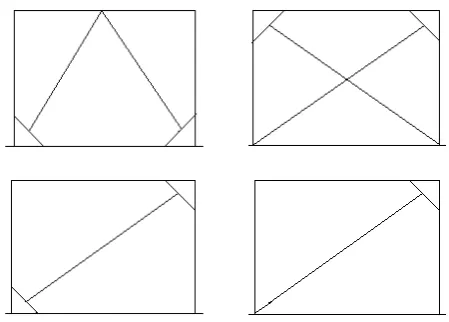
joints. Different types of knee bracing configurations are
shown in Figure 1. Important advantages of this system are as follows:
1. Repair-ability: Due to the behavioral characteristics of knee braces during the earthquake, only the knee member is damaged, so that the main frame and diagonal braces remain normally in an elastic state. As a result, by replacing and repairing the knee, the system can simply be reused. For this reason, the system is called the Disposable Knee Bracing (DKB).
Corresponding author, E-mail: [email protected]
2. System stiffness: the frame displacement in the knee brace system is generally less than the eccentrically brace one, resulting in minimal non-structural damage to the system during vibration.
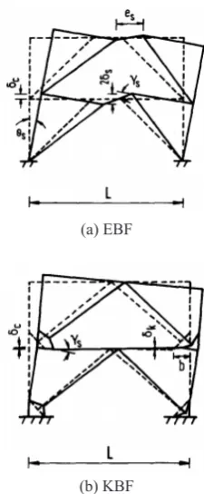
3. Ceiling diaphragm status: It is observed that this system is more rigid than the Eccentric Bracing Frames (EBF). The deformation of the EBF and KBF frames is shown in Figures 2a and b, respectively. It is seen, the ceiling in KBF system is less distorted than EBF system.
(a) EBF
(b) KBF
Figure 2. Frame systems deformation [3]
Mofid and Khosravi (2000) [4] studied the elastic and
nonlinear behaviour of knee bracing system with different arrangement consisting of a frame with a knee brace consisting of beams, columns, knee members and diagonal braces. The research has shown that if the knee element would be parallel to the frame diagonal direction and diagonal element passes through the beam-column intersection according to Figure 3, the structure can have the maximum seismic resistance. By establishing Equation 1, alignment of the parallel knee will be parallel to the diagonal of the frame, and the direction of the brace passes through the beam to column intersection. On the other hand, Equation 2 plays a key role to choose the length of the knee. The parameters, h, H, b, B and lk are shown in Figure 3.
(1) ( ) / ( ) 1b B
h H =
(2)
0.2 h 0.4
H
≤ ≤
Figure 3. The optimum position of the knee brace
Williams et al. (2002) [5] examined the types of knee joint failure. They observed that in order to have a good energy dissipation, the knee member should be in a moment state. They also stablished some recommendations for designing the knee braces. The results indicated that Equations 3 and 4 should be arranged in order to yield the knee joints in moment or shear.
Lk min >4 Mp /Vp (3)
Lk<2 Mp /Vp (4)
In the Equations 3 and 4, the Mp and Vp are the plastic moment and the plastic shear capacity of the knee member, respectively, which can be calculated from Equations 5 and 6:
Vp=tw (d-tf ) Fy/√3 (5)
Mp=tf b(d-tf ) Fy (6)
In these equations, Fy, d, tf, b, tw and Lk are respectively the yield stress, depth, thickness and width of the flange, web
thickness, and the knee length. Daneshjoo et al. [6] examined the effect of geometric parameters and member characteristics on the lateral elasticity of KBF frames. Huang et al. [7] examined the elasto-plastic behavior of the knee bracing. It was observed that changes in the size of the columns relative to the beam were more effective in controlling nonlinear behavior. Naeemi and Bozorg [8] using non-linear and linear static analysis of several knee Braced Frames (KBF) assessed the seismic behavior of this system for controlling the vulnerability of the main and the secondary elements. Investigations showed acceptable results in terms of elastic lateral stiffness, ductility and energy dissipation.
Wongpakdee et al. [9] analyzed performance of a structural steel framing system called Buckling-Restrained Knee Braced Truss Moment Frame (BRKB-TMF). Analyzes
showed very promising results in terms of system efficiency
the plastic hinge formation using a knee member.
Anoushehei and Daneshjoo (2016) [12] examined the geometric parameters and knee bracing behaviour in the steel frame using non-linear Static Pushover analyses (NSP). The results showed that the Equation 7 should be used to select the most appropriate stiffness.
(b/(B )+h/H)<0.6 & 0.1<(b/B،h/H )<0.4 (7) One of the most challenging issues in the design of knee brace systems is how to attach a knee member to a brace member. This research focused on improving the seismic
behavior of knee braces with different fixed joints. The
optimized parameters are including stiffness, damping and ductility. For this purpose, the system’s cyclic behavior with different connection details should be evaluated.
At first, the numerical model is verified by the experimental
data from the literature. Then, three types of knee braced
frames in terms of fixed joints are modelled and analysed. Three fixed joints are: the diagonal member connected to flange of a continuous knee member (KBF-1) from literature
to verify the numerical model, the diagonal member connected to the web of discontinuous knee member (KBF-2) and the stiffened connection similar to KBF-2 (KBF-3) proposed by authors. The studied parameters are elastic stiffness, ductility, and energy absorption, initial and ultimate strengths. 2- Numerical Modelling and Verification
In this study, the ABAQUS/Standard software as ABAQUS and Manual [13] has been used to evaluate the cyclic behaviour of the knee bracing system. The KBF models
consist of five main sections, including: beam, column, knee
member, diagonal brace and connection plate. Three different types of connections between diagonal brace to knee member were modelled here and the results will be compared in the next sections. The mechanical properties of steel material and modelling details are described below.
2- 1- Modelling details and Material Properties
In this study, a numerical model for validation was developed in both the solid element and the shell element.
However, after initial verification, despite the high precision
of both models, according to Figure 8, the solid element was selected to model the other specimens for more accuracy.
Figure 4. Solid Element C3D8R
The solid element C3D8R, according to Figure 4, consists of the 8-node element used the reduced Integral. Each node has three degrees of freedom in the direction of the axes X, Y and Z.
Kinematic hardening model is used to define the yielding
for steel material in ABAQUS Material Library. Properties of steel materials are obtained based on the test carried out by Balendra et al. [14] and are summarized in Table 1.
2- 2- Verification of Finite Element Model
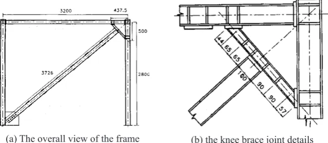
To ensure the modelling results, a knee braced frame tested by Balendra et al. [14] was selected and modelled. Then, the accuracy of modelling was examined by comparing the modelled and tested results. The dimensions of the frame
used for verification are shown in Figure 5, and the cross
sections considered are in accordance with Table 2. The frames were subjected under the quasi-static loading protocol
in verification level according to Figure 6.
2- 3- Boundary conditions, loading, interactions and solutions
With respect to Figure 7a, the rotation and displacement of
the supports were fixed in all directions. The knee elements,
beams, columns and stiffeners are full-bounded. Also, the brace and the connection plates are merged with each other. As shown in Figure 7b, the mesh details in the areas with concentrated stress, especially the knee member and stiffeners,
are finer than the other parts. In addition, sensitivity analysis
on mesh sizes is presented in the following sections.
Figure 6. Loading protocol [14]
Table 1. Mechanical properties [14]
Young’smodulus E
(GPa) Yield stress F(MPa) y Ultimate Stress Fu (MPa) Percent Elongation (%) density valueskg/m3 Poisson coefficient
200 337 617 20 7850 0.3
Table 2. Designed sections according to tested specimen (Balendra et al. [14])
IPB125 Columns
2UNP100 ][ Brace
IPB100 Beam
87×47×10mm Beam stiffener
107×60×10mm Column stiffener
60×95×10mm End plate of knee joint to column and beam
120×120×20mm End plate of knee brace joint
110×110×16mm Continuity plate beam to column
35×30×8mm Brace to column plate
22.35×37×10mm Rectangular stiffener
bf:49mm , d :49mm , tf:6mm , tw:4.3mm Knee Element
(a) The view of the KBF-1 model and related
2- 4- Verification of finite element model based on tests
results
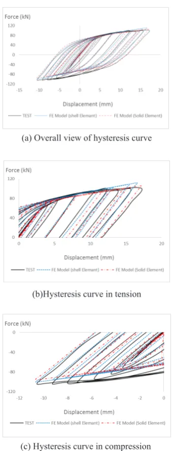
For numerical model verification, the experimental
hysteresis diagram was compared with hysteresis diagrams obtained from models in two cases using shell elements and solid elements. As shown in Figure 8, the models could predict the behavior with a good accuracy. However, a number of
discrepancies can be seen due to simplification in the model,
especially in the behavior of the connections, which are
simplified to complete continuous. According to Figure 8,
despite the fact that shell element has greatly increased the response speed, authors used solid elements in order to more accuracy.
(a) Overall view of hysteresis curve
(b)Hysteresis curve in tension
(c) Hysteresis curve in compression
Figure 8. Hysteresis curve of tested and modelled braces
The model of KBF-1 was analyzed with three different mesh sizes to investigate the sensitivity of models to the mesh size and density (Figure 9). The results showed that the mesh size of 30 mm is the most consistent with the test. Therefore, other models were made with a mesh size of 30 mm.
Figure 9. Mesh size analysis for KBF-1
3- Proposed Joint Models and Discussions
In this study, three different types of connection between diagonal brace to knee member described in Table 3 and Figure 10 were modelled and the results will be compared. The knee member is continuous in KBF-1 similar to Balendra et al. [14], but it is discontinuous (divided by two parts) in KBF-2 and KBF-3 models. The joint of knee member to diagonal brace was stiffened by two triangular plates in KBF-3. The seismic parameters such as load carrying capacity, ductility, elastic stiffness and energy absorption are the subjects of this comparisons.
All of modelled joint types are practical, but the KBF-1 is more practical and easy to use. In this case, the diagonal brace alignment on the knee member and joint welding can be easily accomplished. But, it has limited area for welding and therefore, the KBF-1 joint is more at risk of rupture. For KBF-2 and KBF-3 knee joints, more weld lengths can be made and the connection will be more complete. The rectangular stiffener plates in KBF-3 give more welding lengths and therefore, the rigidity of KBF-3 joint is more than the others.
Pre-constructed joint of knee member to diagonal member could be made and attach to the desired location on the structure. In this method, more precision in measurements is
required so that the two ends of the knee member are fitted
correctly on the beam and column.
3- 1- Review the behavior of the joints
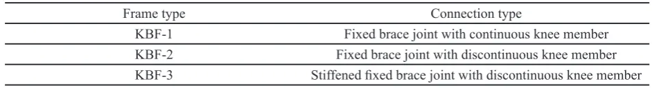
Table 3. Specimen specifications for numerical study
Frame type Connection type
KBF-1 Fixed brace joint with continuous knee member
KBF-2 Fixed brace joint with discontinuous knee member KBF-3 Stiffened fixed brace joint with discontinuous knee member
(a) KBF-1 (b) KBF-2 (c) KBF-3
Figure 10. Corner view of the frame
Figure 11. Loading history
(a) Overall view of hysteresis curve (b) Hysteresis curve in tension (c) Hysteresis curve in compression
According to Figure 13, while the knee member in all models entered in plastic region, neither local buckling nor yielding occurred on beam and column members. Most of the web area in KBF-1 yielded and no yielding was took place
on the flanges. Also in KBF-2, most of the web as well as the flanges near the end connections to the beam and column
were yielded. The plastic deformations and yielding was concentrated in rectangular stiffeners in 3. So in
KBF-3 model, the stress and deformations on web and flanges of
the knee member was reduced and the stress was uniformly distributed on the knee member.
As can be seen in Figure 13, the knee element is designed to dissipate energy under severe seismic loading and therefore brace buckling or yielding of other members of the knee braced frame is prevented [14]. Therefore, discontinuity of
stress flow inside the knee members in KBF-2 and KBF-3
models can be seen. The pushover curve as Figure 14 could be obtained from hysteresis curves after the FE analysis as Figure 12. The maximum capacity in KBF-3 was increased about 10% and 21% compared with KBF-1 and KBF-2, respectively. The use of rectangular stiffeners in KBF-3 increased the frame stiffness and loading capacity.
(a) KBF-1 (Disp.= 0.95 mm, Force=61.1 kN)
(b) KBF-2 (Disp.= 0.79 mm, Force=50.5 kN)
(c) KBF-3 (Disp.= 0.87 mm, Force= 57.2 kN)
Figure 13. The Mises stress contour of studied joints at the end of loading
The initial and ultimate strength of the models can be seen in the Figure 15. According to Figure 15, the KBF-3 had the maximum strength among the models. The curve of KBF-2 was similar to KBF-3 until 8 mm displacement. After that, the strength incremental rate was decreased in KBF-1 due to
shear yielding of almost the entire area of its web and flanges.
So, the ultimate strength of KBF-1 was about 10% less than KBF-3 model.
Figure 14. The envelope of load-displacement cyclic curve
Figure 15. Comparison of the initial and ultimate strengths of the models
To evaluate the seismic parameters such as elastic stiffness, ductility and energy absorption, the equivalent bilinear curves could be used. In this regard, according to the Iranian instruction for seismic rehabilitation [16] according to Figure 16, the point A must be chosen so that: 1- The surface below curve as the non-linear behavior curve must be equal to the polyline OABD surface. 2-Line AB must cut off the non-linear curve in 0.6Fy (point C).
Fu
Fy
0.6Fy
Ke
O C
A
B
D U F
Δy Δu
Seismic parameters are obtained according to the bilinear diagram as follows:
1. Initial strength Fy: The shear force corresponding to point A
2. Ultimate strength Fu: shear force corresponding to point B
3. Elastic stiffness (Ke): slope of the OA line.
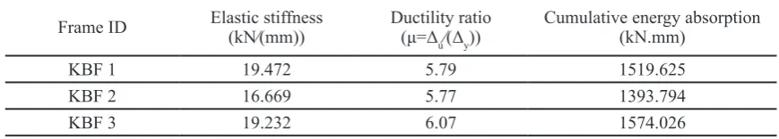
4. Energy absorption: Area under the polyline (OABD) The Table 4 obtained using the bilinear curves of the studied models.
Table 4. Seismic parameters of analyzed models
Frame ID Elastic stiffness (kN⁄(mm)) Ductility ratio (μ=Δ u⁄(Δy))
Cumulative energy absorption (kN.mm)
KBF 1 19.472 5.79 1519.625
KBF 2 16.669 5.77 1393.794
KBF 3 19.232 6.07 1574.026
According to the above results, the KBF-3 had a similar elastic stiffness to KBF-1, but the ductility and energy absorption were promoted about 7% and 4 %, respectively in KBF-3 model. The elastic stiffness and energy absorption in KBF-2 was 14.4% and 8.3% less than KBF-1, respectively,
but the ductility had no significant difference.
It can be said that the of KBF-3 joint in terms of ductility and energy absorption and KBF-1 joint in terms of elastic stiffness showed a better behaviour. Moreover, the KBF-2 model with discontinuous knee member without stiffener had the worst seismic parameters among the models.
4- Conclusions
In this research, at first, the numerical model was verified
by the experimental data from the literature. Then, three types of knee braced frames were modelled and analysed. The studied parameters are elastic stiffness, ductility, and energy absorption, initial and ultimate strengths. The following results are obtained:
• According to the results, the type of knee joint to the
diagonal member has a significant effect on the frame
behaviour.
• The ultimate strength and ductility in KBF-3 model with discontinuous knee member stiffened by two triangular plates increased by about 10% and 7%, respectively in comparison with the KBF-1 model with continuous knee member.
• Energy absorption in KBF-3 model increased by 4% relative to KBF-1 model.
• According to the elastic stiffness parameter of the samples, it can be said that KBF-1 and KBF-3 joints are
not significantly different.
• The KBF-2 model with discontinuous knee member without stiffener had the least seismic parameters among the models.
References
[1] K. Kasai, E.P. Popov, A study of seismically resistant eccentrically braced steel frame systems, Earthquake Engineering Research Center, College of Engineering, University of California, 1986.
[2] J.D. Aristizabal-Ochoa, Disposable knee bracing: improvement in seismic design of steel frames, 112(7) (1986) 1544-1552.
[3] M.-T. Sam, T. Balendra, C.-Y.J.E.s. Liaw, Earthquake-resistant steel frames with energy dissipating knee elements, 17(5) (1995) 334-343.
[4] M. Mofid, P. Khosravi, Non-linear analysis of disposable
knee bracing, Comput. Struct., 75(1) (2000) 65-72. [5] M.S. Williams, A. Blakeborough, D. Clément, N.
Bourahla, Buildings, Seismic behaviour of knee braced frames, Proceedings of the Institution of Civil Engineers-Structures, 152(2) (2002) 147-155.
[6] F. Daneshjou, J. Asgari, Nonlinear analysis of knee-braced frames under earthquake loadings, (2004).
[7] Z. Huang, L. Qing-song, C. Long-zhu, Elastoplastic analysis of knee bracing frame, Journal of Zhejiang University-SCIENCE A, 6(8) (2005) 784-789.
[8] M. Naeemi, M. Bozorg, Seismic performance of knee braced frame, world academy of science, engineering technology, 50 (2009) 976-980.
[9] N. Wongpakdee, S. Leelataviwat, S.C. Goel, W.-C. Liao, Performance-based design and collapse evaluation of buckling restrained knee braced truss moment frames, Engineering Structures, 60 (2014) 23-31.
[10] M. Anitha, K. Divya, Study on seismic behavior of knee braced steel frames, International Research journal of Engineering technology, 2 (2015).
[12] M. Anoushehei, F. Daneshjoo, Geometric parameters and behavior factor of knee-braced steel frames using nonlinear static pushover (NSP) analyses, Comput. Struct., 10(11) (2016) 110.
[13] S.M. ABAQUS, E.U.s. Manual, Hibbitt, Karlsson & Sorensen Inc, Pawtucket, RI, USA, (2010).
[14] T. Balendra, E.-L. Lim, S.-L. Lee, Ductile knee braced frames with shear yielding knee for seismic resistant structures, Engineering Structures, 16(4) (1994) 263-269.
Please cite this article using:
S. H. Khatibi, E. Z. Beydokhti, , M. Yousefi, Cyclic behaviour of the knee braced system considering the type of knee
joints, AUT J. Civil Eng., 3(1) (2019) 13-22. DOI: 10.22060/ajce.2018.15016.5515
[15] AISC, Seismic provisions for structural steel buildings, American Institute of Steel Construction Committee on
Specifications, Chicago, Illinois., 2002.
[16] Office of Deputy for Strategic Supervision Iran,
![Table 1. Mechanical properties [14]](https://thumb-us.123doks.com/thumbv2/123dok_us/10696.2000888/4.595.110.497.366.535/table-mechanical-properties.webp)