IJMF, Iranian Journal of Materials Forming, Vol. 1, No. 2, pp 23-31 Printed in The Islamic Republic of Iran, 2014
© Shiraz University
The Effect of Fe Additive on Plastic Deformation of Crush-Boxes with Closed-Cell Metal Foams, Part II:Al-Composite
Foam-Filled brass tubes Compression Response
S.M.H. Mirbagheri* and J. Khajehali *
Department of Mining and Metallurgical engineering, Amirkabir University of Technology, Tehran, Iran
Abstract: The brass tubes with foam cores of AlSi7SiC3, AlSi7SiC3Fe1 and AlSi7SiC3Fe3 were produced as the crush-boxes with circle and square cross-section. Then axial compressive behavior and energy absorption capability of the foam-filled tubes were investigated during the quasi-static progressive plastic buckling. The uniaxial compressive stress–strain curves of the foam-filled brass tubes exhibited that the compressive stress enhanced smoothly with the increase of the strain and no stress oscillations occurred in the plastic deformation region throughout the tests. The yield stress and the elastic modulus of the foam-filled brass tubes slightly decreased with the increase of Fe wt. % in the foam cores. Moreover, with the increase of Fe powder from 1wt. % to 3wt. %, the absorption energy of the foam-filled brass tubes decreased slightly dependent on the tubes cross-section. The strain-hardening exponent of the tubes with the Al7Si -3SiC-(+Fe) foam cores were found to be lower than the tubes with the Al7Si-3SiC foam cores without Fe. However, the increase of Fe powder from 1wt. % to 3wt. % caused the approximate elimination of strain-hardening and the plastic deformation behavior tends to be approximated to an ideal-plastic behavior up to the densification strain. The results indicate that all of the compression responses are due to the Micro and Macro-defects within the foams cellular structure as well as the tubes cross-section geometry.
Keywords: Metal foam, Composite, Brass tube, Plastic buckling, Compression response, Absorption energy, Intermetallic compound, Foam-filled tubes
1. Introduction
Aluminum closed-cell foams have developed in variety of industries, due to their unique combination of mechanical and physical properties [1–3].They demonstrate a distinct and high energy absorption capacity during compression test under uniaxial loading [3]. In auto industry, thin-walled tubular structures have been applied as energy absorbers or crush-boxes because of their progressive plastic buckling under uniaxial compressive loading. The crush of the thin-walled tubes is dependent on thickness, size, shape of cross-section, and material of tubes [3-4]. In recent decades, engineers have attempted to replace the empty space into the thin-walled tubes by the metal foam cores. The result of replacing indicated that foam-filled tubes stabilize the irregular plastic buckling pattern that led to the improvement of energy absorption up to 30% [4-6]. In fact, the metal foam provides internal support for the tube thin wall so that it causes to create more plastic hinges per unit length of tube. Therefore, the absorption energy during progressive plastic buckling under uniaxial quasi statics will be increased [5, 7]. Studies done by Langseth et al., show that plateau stress for the metal foam-filled tubes is higher than the algebraic summation of plateau stress of the empty tube and the meal foam itself. Moreover, area under their stress-strain curves of the foam-filled tubes approximately illustrated an increase of 30-40% with respect to the empty tubes
Received by the editors May 28, 2014; Revised August 5, 2014 and Accepted August 26, 2014.
S. M. H. Mirbagheri
October 2014 IJMF, Iranian Journal of Materials Forming, Volume 1, Number 2 24
8]. A nominal compressive stress-strain curves of the foam-filled tube has three regions including: i) elastic deformation, ii) soft plastic deformation together with cells crushing at long plateau stress up to densification strain, iii) hard plastic deformation after densification strain or bulk deformation with ultra strain-hardening rate. However, the curve of the soft plastic deformation (long plateau stress) region has different pattern such as exponential, power law, linear, wave oscillations, and mix of them [6, 8]. It is possible that the wave oscillations of the plateau stress eliminated by changing the composition and the cellular structure of metal foam cores. It has been reported that the presence of ceramic particles and chemical elements in the foam liquid leads to become brittleness, helps to create the wave oscillation and the strain-hardening in the region (ii) of the compressive stress-strain curve [9]. In this case, there are a lot of papers about mechanical properties and absorption energy of Al foam, Al- alloys foam, and Al composites foam as filler of thin-walled steel tubes [4-5, 9]. Quality of the Al composite foams has significant influence on the pattern of the elastic and the plastic deformation of the foams and Al composite foam filled tubes [10-11]. Results show the interaction between the tubes and the filler metal foam, which leads to higher energy dissipation and changed progressive plastic buckling modes. Experiments present that the buckling process of thin-walled tubes is accompanied by progress of localized plastic mechanisms and some folds are appeared on the wall of tubes. Therefore, the numerical analysis and computer simulation of the filled thin-walled tubes is very complicated. However, some papers that simplified mechanisms were proposed to predict and modeled the buckling response of the filled tubes for simple shape (circular and square) under variety loading conditions. The simplified models lead to simple solution and therefore, can be used efficiently in preliminary design of energy absorbing systems [3, 5, 11]. However, such models are limited to aluminum and steel tubes and they are not a model or report for the brass tubes.
Therefore, in this investigation as the second part of the paper with reference number [12], attempt has been made to evaluate the effect of the AlSi7SiC3(Fe) foams as filler of thin-walled brass tubes and its cross-sectional shape on the behavior of progressive plastic buckling, under the condition of quasi-static uniaxial compression load.
2. Experimental procedures
In order to investigate the mechanical properties of energy absorber elements during plastic deformation, three types of tubes with foam cores, namely AlSi7SiC3, AlSi7SiC3Fe1, and AlSi7SiC3Fe3 with 25-32 PPI, were prepared based on a method that have been mentioned in Part-I [12]. Two types including circle and square tubular moulds with the thickness of 1 mm, and outside diameters of 22 mm and square cross-section of 22x22 mm were cut with the height of 1.5 times of their diameters from 70Cu-30Zn brass tubes, respectively. The uniaxial quasi static loading on the foam-filled tubes were then performed using 25 kN
Instron 8502 test machine at a crosshead speed of 2.5 mm/minute and 1.3x10⁻³ (1/sec) strain rate at room
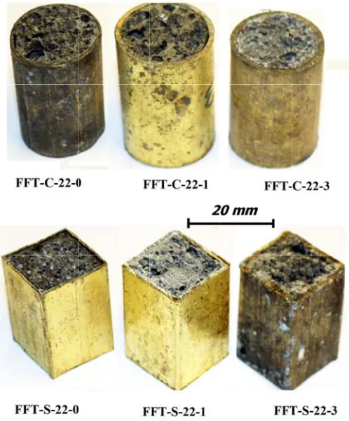
IJMF, Iranian Fig. 1. Fo
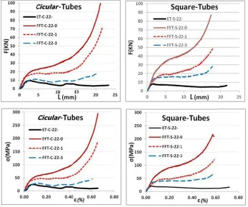
3.1. Compre Figure 2 sh AlSi9SiC3 compressive that alike th 4, 13-14]. F Then a long progressive tube folding because the between the tubes with f more resista tubes with c with the squ foam cores However, in stress for al cores conta
α+β phases hardening e
n Journal of M oam-filled Cu
ession respo hows the eff composite e response o he compressi First the elas
g plateau of plastic buck g. Finally, th e rate of wor
e adjacent fo foam cores a ance during circle cross-uare cross-se
had not sign n the plastic ll the foam-f ining Fe is d for wt. % F exponent for
The ef
Materials Formi u-30Zn brass t
onse
fect of Fe w foams filled of the empty
ve stress–str stic strain zo f plastic defo kling associa here is a den rk-hardening olds of the tu and without c
plastic defor section, the ection. In oth nificantly aff c region, the
filled tubes due to dispe Fe < 2 or α
r all samples
ffect of Fe addi
ing, Volume 1, tubes before c
3. Res
wt. % on th d-tubes with
brass tubes rain curves o one, which t formation at ated with cru nsification st g is limited e
ube walls. It containing a rmation in c strain-stress her words, it ffected on the e addition of
had consider rsion of the
α+δ phases f s, during plat
itive on plastic
Number 2 ompression te
sults and dis
e force-disp h circular a was present f other Al fo the stress lin an approxim ushing of ce
train region either by the is observed any Fe eleme omparison w s curves thro t can be dedu
e compressio f Fe on the w
rable impact intermetallic for wt. % Fe teau plastic
deformation of
est. Top: circle
scussions
placement an and square c
ed for comp oam-filled tub nearly increa mately smoo ellular structu in associatio densificatio in Fig. 2 tha ent, namely F with the foam ough the plas
uced that the on stress–str work-harden t. It seems th c compound e > 2 [12]. T
deformation f …
e section, Bot
nd the stress cross-section arison in Fig bes, it had th ases with inc oth stress oc
ure of the fo on with abru n of the foam at both the s FFT-S-22-0 m cores with
stic strains a e presence of rain response ning phenom hat brittlene ds within foa Therefore, th n, can be not
Oc ttom: square s
s–strain curv n, respective g. 2. Results hree distinct creasing of t curs, which oam core and
upt increase m cores or i quare and th and FFT-C-2 h Fe. Further are less than f Fe element e at the elast menon and th
ss of compo am cells wall he behavior ted and analy
ctober 2014 25
ection.
October 2014 26
flow stress "n" is the st variation of after the elim
Fig. 2
Two s mechanism plastic defo hardening e strength coe
F
of a materia train-hardeni
f ln with
mination of t
2. Compressio plastic b
strain-harden belongs to ormation an exponent "n2
efficients (k)
Fig. 3. Plot of
l is generally ing exponent
h ln for a
the elastic re
on response o buckling. Top
curves, Left
ning mechan the low str d the secon 2" or hard pl for all the fo
f ln(σ) versus l
S. M
y expressed t, and "k" is t all the comp egion based o
f the foam-fill row: Force-d t column: Circ
nisms can b rain-hardenin nd mechanis
lastic deform oam-filled tu
ln(ε) for plast
M. H. Mirbaghe
IJMF, Irania as a function the plastic st posite foam f on the presen
led tubes duri displacement c cle tube, Right
be noted for ng exponent m for strain mation. The s ubes have bee
ic deformation eri
an Journal of M n of plastic s trength coeff filled-tubes a nted idea in r
ng the uniaxia curves, Bottom t column: Squ
r all foam-f "n1", befor ns after the strain-harden en presented
n zone, obtain
Materials Form
strain by σ =
ficient [15-17 at the plastic reference [17
al and quasi st m row: Stress-uare tubes.
filled tubes re the densif densificatio ning exponen d in Table 1.
ned from curv
ming, Volume 1 = K εn equatio
7]. Figure 3 c deformatio 7].
tatic progressi -strain
in Fig. 3. fication strai on strain wi nts (n) and t
es of Fig. 2.
1, Number 2 on, where shows the on regions
ive
The effect of Fe additive on plastic deformation of …
IJMF, Iranian Journal of Materials Forming, Volume 1, Number 2 October 2014 27
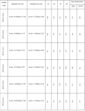
Table 1. Determine the "n" and "k" coefficients of strain-hardening equation for all samples in Fig. 3, based on procedure mentioned in Ref. [12]
sample
code Equation for (n1) Equation for (n2) n1 n2 k1 k2
lines intersection
ln(ε) ln (σ)
FF
T-C-22-0 ln (σ) =0.36ln(ε)+3.136 ln (σ) =2.25ln(ε)-3.88
0.
4
2.
2
3.
1
-3.
9
3.
7
4.
5
FF
T-S
-22
-0
ln (σ) =0.44ln(ε)+3.15 ln (σ) =1.86ln(ε)-2.22
0.
4
1.
9
3.
2
-2.
2
3.
8
4.
8
FF
T-C
-22-1 ln (σ) =0.11ln(ε)+3.52 ln (σ) =2.58ln(ε)-5.68
0.
1
2.
6
3.
5
-5.
7
3.
7
3.
9
FFT-S-22-1
ln (σ) =0.31ln(ε)+2.97 ln (σ) =2.42ln(ε)-5.01
0.
3
2.
4
3.
0
-5.
0
3.
8
4.
1
FFT
-C-22-3
ln (σ) =-0.06ln(ε)+3.39 ln (σ) =1.58ln(ε)-2.70
-0.
1
1.
6
-3.
4
-2.
7
3.
7
3.
2
FF
T-S-22-3
ln (σ) =0.073ln(ε)+3.46 ln (σ) =1.55ln(ε)-2.16
0.
1
1.
6
3.
5
-2
.2
3.
8
3.
7
It can be observed from Table 1 that the addition of Fe element significantly affects the strain-hardening exponent of the filled tubes. The strain-strain-hardening exponent of the AlSi9SiC3Fe3 foam-filled tubes is lower than the AlSi9SiC3 foam-foam-filled tubes for both the square and the circle cross-section.
Therefore, coefficient varieties of "n1" and "k1" from equation were plotted up to the strain
densification (soft deformation) for both the square and the circle tubes with foam cores in Fig. 4. In Fig. 4, for the foam-filled tubes, the increase of Fe powder from 1 to 3wt. % causes a decrease in the strain hardening exponent "n1" from 0.4 toward 0.1 and then to -0.1 for the circle tubes, and also from 0.4 toward 0.3 and then to 0.1 for the square tubes. However, coefficients of k1 are approximately constant (3.2±0.25) for the square tubes in spite of the circle tubes. It seems that varieties of "n1" and "k1" for the square tubes are more reliable than the circle tubes for different foam cores. Because the negative coefficient of "n1=-0.1" for FFT-C-22-3 sample indicates a structural defect in the foam core to exist. Whereas, the square tubes have a constant plastic strength coefficient "k" and their strain-hardening exponent "n" decrease with the increase of Fe element (see Fig. 4). Therefore, the addition of Fe within the AlSi9SiC3 foam core can change positive slope of the strain-stress to a slope of approximately zero in plastic deformation region. In other words, there is a horizontal line on the stress-strain curves during the densification strain individually for the square tubes with 3wt. % Fe (i.e. n1=0.4 toward n1=0.1).
n
K
October 2014 28
F
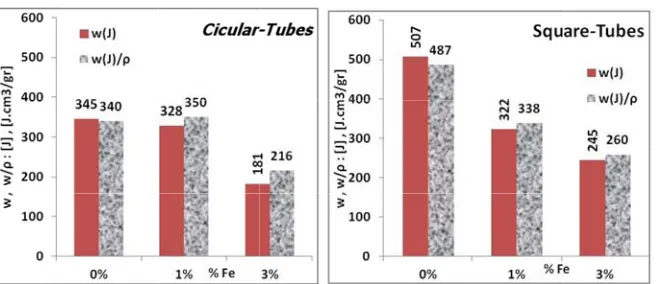
3.2. Mechan Figure energy abso characterist were extrac characterist square cross composite f strange beh decrease an noticeable. cores and th
Fig. 5
Fig. 4. Varities
nical proper 5, 6, and 7 orption capac
ic yield stres cted from th ic yield stres s-section. Th foams filled-avior for mo nd then increa
It seems this he shape of th
. Yield stress foam-fil
Fig. 6. Modul bucklin
s of the plastic the foa
rties of foam 7 show the e
city (w) of th
ss ( / )
he elastic zo ss decreases he variation o
-tubes as a f odulus. This i ase in spite o s behavior de he tube cross
and character lled tubes und
lus and the ch ng of foam-fill
S. M
c strength coef am-filled tube
-filled tubes effect of Fe
he foam-fille for the foam one of Fig.
significantly of the elastic function of th
is because th of samples w epends on re s section on s
ristic stress yie der uniaxial lo
haracteristic m led tubes unde
M. H. Mirbaghe
IJMF, Irania fficient "k" an s with foam c
additive on ed tubes, res m-filled tube 2. It is ob y with the inc c modulus (E
he wt. % Fe he elastic mo with circle cr eaction betwe
solidification
eld obtained fr oading. Left: S
modulus obtain er uniaxial loa eri
an Journal of M nd the strain-h
ores including
yield stress pectively. Fi s in order to bserved that
crease of Fe E) and the ch
e was plotted odulus of the ross-section. een the Fe-re n rate of the
from curves of Square tubes. R
ned from curve ading. Left: Sq
Materials Form hardening expo
g Fe.
s (σmax), elas igure 5 show o facilitate co both the y element, esp haracteristic m
d in Fig. 6. R square cross However, th each interme foam core du
f Fig.2 during Right: Circle t
es of Fig.2 du quare. Right C
ming, Volume 1 onent "n" for
stic modulus ws yield stres omparison. T yield stresses pecially for t
modulus ( /
Results dem s-section tub hese variation etallic within
uring the pro
the plastic bu tubes.
uring plastic Circle.
1, Number 2 s (E), and ss (σ) and These data s and the tubes with
/ ) for the
onstrate a es, at first ns are not n the foam oduction.
IJMF, Iranian Fi In Fig. is illustrated where, lowe the densific and present (w/ρ) of the that the ene circle cross are slightly the AlSi7Si tubes with t yield and lo exponent of
Figure comparison energy valu of the comp 22-, did not fold) in spit the FFT-S-2 at Fig. 9, pr the FFT-C-2 plastic buck cores within creating mo energy in co better absor strain-harde
n Journal of M ig. 7. Absorpt prog
7, the absor d. W, calcula
.
er limit of in cation strain
ted at last co e composite f ergy absorbin sections. H higher than iC3Fe1 foam the FFT-S-22 onger densif f these foams
8 shows a n. It is observ ue (between 2 posite foam c t present a g te of the FFT 22-0 tubes w roved this cla 22-1, the FFT king behavio
n tubes give ore plastic fo
omparison w rption energy ening expone
The ef
Materials Formi tion energy an gressive plast
rbed energy ated from Eq
ntegration (ε0 and it is det olumn of Tab
foams are pl ng capacity However, for
the normal a m-filled tube 2-1 and the F fication strain s in Fig. 3 an absorption en
ved that both 2-3 times) in cores withou good progres T-C-22-0 and with samples aim. Howeve T-S-22-1, an r in spite of e an internal lds per unit l with the AlSi y when they ent relative to
ffect of Fe addi
ing, Volume 1, nd characterist ic buckling of Left: Circle
during the p . (1) [3, 16]:
0) is the end ermined from ble 1. The ab lotted as a fu
for tubes wi both square absorption en es are more FFT-S-22-3
n (εd) of the nd Table 1.
nergy value h tubes of the n comparison ut Fe element ssive plastic d
FFT-S-22-of the ET-S er, for the co nd the FFT-C
their lower a l support for length. Howe i7SiC3Fe1 fo y are filled w o the AlSi7S
itive on plastic
Number 2 tic absorption f foam-filled t e Tubes. Right
rogressive p
of the elasti m intersectio bsorbed ener unction of wt ith the squar e and circle nergy. It can
than the Al codes. This c ese foams (se
es of the em e FFT-C-22-n to both the t. However, bucking at -0 tubes. The -22- and the omposite foam C-22-3, the F
absorption en r tubes wall, ever, the AlS oam cores. T with the AlSi SiC3Fe3 foam
deformation of
energy obtain tubes under un t: Square tube
lastic buckli
ic strain. Th on of the line rgy (w) and t t. % Fe for co re cross-secti
section, the be noted fro lSi7SiC3Fe3 can be attrib ee Fig. 2), a
mpty tube a -0 and the FF
empty tubes the empty tu Fig. 9 (i.e. n e apparent co ET-C-22-, a m cores cont FFT-S-22-3 h nergy. This i , shortening Si7SiC3Fe3 f Thus, both th
i7SiC3Fe1 fo m cores (Fig.
f …
ned from curv niaxial loading
s.
ng of compo
e upper limi es in Fig. 3, the character omparison in ions are mor
characteristi om Fig. 7, the samples, in uted for two and ii) the hi
and the all FT-S-22-0 h s, which is du
ubes, namely no higher sy omparison o after uniaxia taining of the have presente s because th
the wavelen foam cores s he square and foam cores in
. 4).
Oc ves of Fig. 2 du
g.
osite foam-fi
it of integrati which were ristic absorb n Fig. 7. Res re than the tu ic absorption e energy abs ndividually f o reasons: i) t igher strain-h
foam filled-have higher a ue to cellular y ET-S-22- a ymmetric an f the FFT-C l compressiv e Fe element ed a better pr e AlSi7SiC3 ngth buckles show lower a d the circle tu
n spite of th
ctober 2014 29
uring
illed tubes
(1)
October 2014 30
Theref composite f of (α+δ) ph at AlSi7SiC the cell-wal deduced tha good progre which can containing 3
i) The foam 1.2 to 3 tim foam core a walled tube ii) Cellular progressive length.
Fig. 8
Fig. 9.
fore, the co filled-tubes. A
ases for wt. C3Fe1 sample
ll or around t at foam fille essive plasti rise energy 3 wt. %Fe.
m filled brass mes relative t and the chara s are their cr structure an plastic buc
8. Comparison
. Behavior of and squa
oling rate c At low cooli % Fe > 2 is es due to the the micro-vo ed-tubes with ic buckling d
absorption
s tubes durin to the empty acteristic of t ross-sectiona nd Micro-stru ckling of the
S. M
n of absorptio
progressive p are cross-secti
could chang ing rates, the
formed unde e presence of oid within the h 1 wt. % Fe due to suitab and increas
ng the comp y brass tubes the thin-wall al shape and t
ucture of co e foam-filled
M. H. Mirbaghe
IJMF, Irania n energy amo
lastic bucklin ion after uniax
ge the micr e wall contain
er high coolin f the concent e cells-platea e for both th ble distribut e the harden
4. Conclusi
pressive load s. This incre led tubes. Mo
their size. omposite foa d brass tube eri
an Journal of M ong all thin-wa
ng foam–filled xial compressi
rostructures ns (α+β) for
ng [12]. Also tration of stre au region. Ba he circle and tion of plasti ning-strain e
ion
ding increase easing factor ore importan
ams had a si s, especially
Materials Form alled brass tub
d brass tubes w ive loading.
of cell wal wt. % Fe < 2 o an addition ess around th ased on the a d the square ic hinge poi exponent in
e the absorpt r depends on ntly, the char
ignificant ro y for folds n
ming, Volume 1 bes.
with circle
lls in AlSi7 2 while a com nal energy is he intermetal above results cross-sectio ints at the tu
spite of the
tion energy m n the propert
racteristics of
le on the be numbers per
1, Number 2 7SiC3(Fe) mbination s absorbed llic within s, it can be ns have a ubes wall, e samples
more than ties of the f the
The effect of Fe additive on plastic deformation of …
IJMF, Iranian Journal of Materials Forming, Volume 1, Number 2 October 2014 31
iii) During the AlSi7SiC3(Fe) foaming process by powder metallurgy route, some intermetallic such as
α+β and α+δ formed dependent on the cooling rate and the percentage of Fe, which can strongly affect on
mechanism of the plastic hinge formation.
iv)The Fe additive in the composite foams affected on the strain-hardening exponent of the foam-filled tubes so that the foam with 3 wt. % Fe, the strain-hardening can be approximately eliminated, individually for the square cross-sectional tubes because the strain-hardening exponent for tube with AlSi7SiC3 foam core reduced from n=0.4 toward n=0.1 for AlSi7SiC3Fe3.
v) All foam-filled brass tubes revealed the work-hardening phenomenon during the uniaxial compression loading; however additional 3wt. % Fe within the foam core can eliminate the work-hardening.
5. References
[1] J. Baumeister, J. Banhart and M. Weber, Materials and Design, 18 (1997) 217–220.
[2] T. Mukai, T. Miyoshi, S. Nakano, H. Somekawa and K. Higashi, Scripta Materialia. 54 (2006) 533–537. [3] A.G. Evans, M.F. Ashby, N.A. Fleck, L.J. Gibson, J.W. Hutchinson and H.N.G. Wadley, Metal Foams: A
Design Guide, (2000), Elsevier.
[4] M. Seitzberger, F.G. Rammerstorfer, R. Gradinger, H.P. Degischer, M. Blaimschein and C. Walch, Experimental studies on the quasi-static axial crushing of steel columns filled with aluminum foam, Int. J. Sol.
Struct. 37(2000) 4125-4147.
[5] M. Seitzberger, F.G. Rammerstorfer, H.P. Degischer and R. Gradinger, Crushing of axially compressed steel tubes filled with aluminum foam, Acta Mech. 125(1997) 93-105.
[6] T. Daxner, H.J. Böhm, M. Seitzberger and F.G. Rammerstorfer, Modeling of Cellular Materials, Handbook of Cellular Metals. 2002: (Eds.:H.P.Degischer, B.Kriszt), pp. 245-280; Wiley-VCH, Weinheim, Germany. [7] M. Langseth, O.S. Hopperstad and A.G. Hanssen, Crash behavior of thin-walled aluminum members,
Thin-Walled Structures, 32(1998) 127–150.
[8] M. Langseth A.G. Hanssen and O.S. Hopperstad, Optimum design for energy absorption of square aluminum columns with aluminum foam filler. International Journal of Mechanical Sciences, 43 (2001) 153-176.
[9] A. Bastawros, H. Bart-Smith and A.G. Evans, Experimental analysis of deformation mechanisms in a closed-cell aluminum alloy foam, Journal of the Mechanics and Physicsof Solids, 48(2000) 301-322.
[10] A.K. Toksoy and M. Guden, Partial A: Foam filling of commercial 1050H14 crash boxes: the effect box column thickness and foam relative density on energy absorption, Thin-walled structures 48(2010) 482-494.
[11] W. Yan, E. Durif, Y. Yamada and C. Wen, Crushing Simulation of Foam-Filled Aluminum Tubes, Materials
Transactions, 48-7 (2007) 1901-1906.
[12] S.M.H. Mirbagheri and J. Khajehali, The effect of Fe additive on plastic deformation for crush-boxes with closed-cell metal foams, Part I: Al-composite foam compression response, Iranian Journal of Materials
Forming, 1-1(2014) 32-45.
[13] W. Deqing and S. Ziyuan, Effect of ceramic particles on cell size and wall thickness of aluminum foam.
Materials Science and Engineering A, 361(2003) 45–49.
[14] J. Banhart, Manufacture, characterization and application of cellular metals and metal foams, Progress in
Materials Science, 46(2001) 559-632.
[15] Mondal, M.D. Goel and S. Das, Effect of strain rate and relative density on compressive deformation behavior of closed cell aluminum-fly ash composite foam, Materials & Design, 30 (2009) 1268-1274.
[16] M. J. Khajeali, Compressive response of the composite metallic foam filled-tubes and effective parameters,
M.Sc. Thesis, Amirkabir University, 2011.
[17] A. Daoud, Compressive response and energy absorption of foamed A359–Al2O3 particle composites, Journal of