http://www.sciencepublishinggroup.com/j/jenr doi: 10.11648/j.jenr.20180703.12
ISSN: 2330-7366 (Print); ISSN: 2330-7404 (Online)
Study of Flow and Heat Transfer Performance in Different
Detached Cooling Modules
Jiahong Fu
1, *, Zhang Wei
21
Department of Mechanical Engineering, Zhejiang University City College, Hangzhou,China
2Power Machinery and Vehicular Engineering Institute, Zhejiang University, Hangzhou, China
Email address:
*
Corresponding author
To cite this article:
Jiahong Fu, Zhang Wei. Study of Flow and Heat Transfer Performance in Different Detached Cooling Modules. Journal of Energy and Natural Resources. Vol. 7, No. 3, 2018, pp. 83-91. doi: 10.11648/j.jenr.20180703.12
Received: July 31, 2018; Accepted: August 13, 2018; Published: December 20, 2018
Abstract:
Numerical and experimental studies were conducted to investigate the flow and heat transfer performance in different detached cooling modules with multiple types of heat exchangers, considering the typical dual heat exchangers in construction machinery cooling modules as examples. The porous media model was used to simulate the heat exchangers, and the multiple reference frame method was used to simulate fan performance. A numerical simulated model of vehicular cooling module was established and verified by experiment. On the basis of it, the numerical study of vehicular detached cooling modules was carried on. First, the detached cooling modules with serial structure were sat up, the influence of position and quantity of air intakes to cooling performance was studied. Then the detached cooling modules with non-serial structure were established, the influence of the position between heat exchangers (HEs) and fan was taken into account. The analysis showed that when the detached cooling modules were arranged in a tandem structure, the number of cooling air inlets was not effective for the performance improvement. When the same heat exchangers and fan were reconstructed in a non-series configuration, the performance improvement was significantly for the heat exchangers were relatively independent and wouldn’t interfere with each other. However, the requirements for the installation space were also severer. What’s more, the relative position between the heat exchangers also had an obvious influence on its performance. The dual heat exchanger non-series structure detached cooling module scheme had more advantages in performance than that in the single heat exchanger scheme or the tandem scheme, and had a higher cooling efficiency. Comparing to tandem cooling module, the detached cooling module can achieve the same heat dissipation at a lower fan speed, reduce the fan power consumption, and can achieve precise cooling on the basis of the controllable blinds installed at the heat exchanger inlet.Keywords:
Fluid Flow and Heat Transfer, Construction Machinery, Detached Cooling Module, Heat Exchanger1. Introduction
In the field of commercial vehicles and construction machinery, with the continuous increase of engine power density, heat exchangers with different volumes and functions are increasingly used in vehicle cooling systems [1]. The contradiction between the position of the power cabin and the increasing heat load of the heat exchanger is becoming more and more prominent. In order to solve the contradiction, foreign well-known construction machinery manufacturers have separated the fan and heat exchanger module to form a separate cooling module to improve the condition of the heat
exchanger’ s cooling air inlet temperature and flow condition, to improve the cooling efficiency. A similar conceptual design was also been proposed by Han Song [2] of Zhejiang University. Since the heat exchanger is in a "stereoscopic" arrangement and the flow field is generated by the cooling fans, the flow organization of the cooling air is not only uneven but also manifests as a multi-dimensional feature. Therefore, the flow heat transfer performance test of such new structural cooling modules cannot be carried out in the traditional heat exchanger wind tunnel, and new methods need to be developed to support related research work.
Zhang Yi [5] carried out the wind tunnel test study on the factors affecting the performance of the vehicle cooling module. Jörg Soldner [6] proposed a similar independent cooling module design and conducted related numerical simulation studies. However, the research on the three-dimensional non-uniform flow field caused by the multi-heat exchanger and the cooling fan which are set in the independent cooling module is rarely reported in China. Only Du Xueping [7] used a test method to study the effect of angular changes between cooling tower heat exchangers on their cooling performance. Therefore, this paper uses the numerical simulation method to study the performance of the independent cooling module. Based on the previous research, the performance difference between the series and non-series structure independent cooling modules is further compared and analyzed, which indicates the direction for the design of the independent cooling module.
2. Numerical Simulation Model
2.1. Heat Exchanger Model
This paper studies the performance of heat exchangers in different flow fields. The heat exchanger is thus simplified to a porous medium model. In this way, a momentum source term is added to the porous medium region so that the drop in pressure gradient is proportional to the velocity within the region. There are two important parameters for characterizing porous media: viscous drag coefficient and inertial drag coefficient, which are derived from a fitting formula: ∆p =av+bv2, where v represents the different air flow rates of the heat exchanger and ∆p represents the core pressure drop at this flow rate v. More details on porous media can be found in the reference [8]. This paper uses one-dimensional simulation to simulate the heat transfer characteristics of heat exchangers. In the method, the heat exchanger is divided into a plurality of sub-heat exchangers, and the efficiency of each sub-heat exchanger can be obtained according to the efficiency-heat transfer unit number method calculation formula [9] of the cross-flow heat exchanger and the heat exchange amount of each sub-heat exchanger be obtained according to the inlet temperature on the cold and hot side of each sub-heat exchanger. The specific calculation process is as follows:
According to the definition formula of heat exchanger performance:
0.22
* 0.78 *
1 exp [exp( ) 1]
= − − −
NTU
C NTU C
ε (1)
Where, heat transfer efficiency
max
= q
q
ε characterizes the
ratio of the actual heat transfer rate to the maximum possible
heat transfer rate of the heat exchanger; * min
max
= C
C
C is the
heat capacity rate ratio; the number of heat transfer units
min
= UA
NTU
C is a dimensionless measure of the heat transfer
dimension of the heat exchanger.
Divide the NTU to each sub-heat exchanger according to the heat exchanger scale to obtain the performance of each sub-heat exchanger. By taking the average value of the gas temperature at the boundary as the inlet temperature of the sub-heat exchanger, the heat exchange amount of each sub-heat exchanger can be obtained as:
( ) ( )
min hot cold
macro min in,auxiliary in,primary
min ,
(
)
=
=
−
ɺ p ɺ p
mc mc
q
C
T
T
C
ε
(2)
After obtaining the heat transfer amount of the previous sub-heat exchanger, according to the energy conservation equation:
( )
auxiliary(
out in)
macro min
(
in,auxiliary in,primary)
−=
−
=
ɺ
m h h
q
ε
C
T
T
(3)
Where, hout and hin are respectively the enthalpy of inlet and outlet of the cold side medium of each radiator unit. Then the outlet temperature of the sub heat exchanger is:
out out , = p auxiliary h T
C (4)
This temperature is the inlet temperature of the latter sub heat exchanger; therefore, the total heat transfer of the heat exchanger is:
total macro, , 1 1
= =
= =
=
∑∑
i n j n i ji j
Q q (5)
Generally, in a low NTU, small temperature difference cross-flow heat exchanger, the longitudinal heat conduction between the internal heat exchange units can be neglected [10], because the ratio of heat exchange to the total heat exchange capacity of the heat exchanger is less than 1%, so The heat transfer between the sub-heat exchangers is also ignored in this model.
2.2. Fan Model
The multi-reference frame coordinate method (MRF) is used to simulate the fan flow field. In the method, the calculation domain is divided into absolute coordinate region and fan rotation region, and a rotating reference coordinate system is established in the rotation region. The internal control equation is converted by the formula (6):
r
v = v + ω×r (6)
Where,
v
r is rotating coordinate system speed,v
ismoving speed,
ω
is rotational angular velocity. After the conversion, it is equivalent to adding the rotational acceleration and the centripetal acceleration to the momentum equation. The MRF model contains the fan blade geometry model, so the pressure step characteristics of the fan and the rotation characteristics of the flow field can be directly obtained by numerical simulation, and are no longer dependent on the experimental values. Although this model is only a constant approximation solution, the error between the simulation result and the experimental value is within the acceptable range of engineering error after reasonable selection of the rotation region [11-13].This paper uses the RNG k-ε turbulence model [14-15]. This turbulence model considers the rotation in the flow, and can better handle the flow with high strain rate and streamline bending situations, and has higher accuracy for the simulation of rotating machinery such as fans. The near wall is handled
by the wall function method. The rotating area of the fan is an enclosed space formed by the air hood and the outer surface of the fan [16-17]. When the mesh density is 0.5 mm to 2.5 mm, a mesh-independent solution is obtained, and therefore, the fan face mesh density is set to be 2.5 mm.
3. Test Verification
This paper establishes a numerical simulation model of the series structure cooling module, as shown in Figure 1. The model consists of a charge air cooler (CAC) model, a water radiator (RAD) model, and a cooling fan model (FAN). Figure 2 shows the three-dimensional numerical simulation of the flow field. It can be seen from the figure that the numerical simulation can obtain the three-dimensional uneven flow field generated by the fan.
Figure 1. Simulation model of cooling module with serial structure.
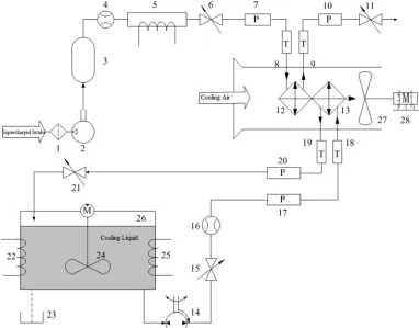
In this paper, the numerical simulation model is tested and verified on the vehicle cooling module simulation test system. The system is shown in Figure 3. The system uses the cooling module shown in Figure 1 as the test object. The heat source simulation system simulates the system energy distribution
when the heat exchanger is running, studies the heat transfer characteristics of the cooling module, and changes the cooling fan speed with the variable frequency motor to simulate the running condition of the cooling fan and study the flow and resistance characteristics of the vehicle cooling module.
Figure 3. Schematic diagram of simulated cooling module test system.
1-air filter; 2-air compressor; 3-gas tank; 4, 16-flow meter; 5, 22, 25-electric heater; 6, 11, 15, 21-flow regulating valve; 7, 10, 17, 20 - pressure sensor; 8, 9, 18, 19 - temperature sensor; 12 - charge air cooler; 13 - water tank; 14 - electric pump set; 23 - drain pipe; 24 - stirring device; 26 - water storage tank;27-fan; 28-inverter motor.
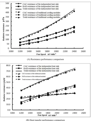
The comparison between the calculated value of the cooling resistance of the cooling module and the experimental test value is shown in Figure 4. As can be seen from Figure 4, the experimental values are consistent with the simulated values. Considering the difference between the experiment and the simulation, the error is basically within the acceptable range.
Figure 4. Flow resistance comparison between exp. and simulation.
Figure 5. Heat transfer comparison between exp. and simulation.
simulation model still has certain engineering application value.
4. Numerical Simulation Analysis of
Independent Cooling Module
In this chapter, the intercooler (CAC) model, the water radiator (RAD) model, and the cooling fan (FAN) model are used to construct a stand-alone cooling module calculation scheme. The effects of series and non-series independent cooling modules on the cooling performance of the heat exchanger are studied. Each calculation scheme adopts a
unified numerical simulation boundary, and the fan adopts an air suction fan.
4.1. Performance Analysis of Series Structure Independent Cooling Module
The calculation schemes of the single inlet and the double inlet of the series-connected independent cooling module are respectively established, as shown in Figure 6. Compare the effects of different inlet locations and quantities on the same cooling module. Figure 7 shows the temperature field and streamline distribution for different calculation schemes.
Figure 6. The simulating schemes of detached cooling module with serial structure.
Figure 7. Streamline and temperature filed of serial schemes.
It can be seen from Figure 7 that although the cooling air at the entrance under different calculation schemes are different, the internal flow and temperature field distribution of the heat exchanger module are similar. The cooling module performance curve shown in Figure 8 further proves that for the series-connected independent cooling module, the single
(A) Resistance performance comparison
(B) Heat transfer performance comparison
Figure 8. Performance comparison of radiator module at different configurations.
4.2. Performance Analysis of Non-series Structure Independent Cooling Module
Figure 9. The simulating schemes of detached cooling module with non-serial structure.
non-series configuration, there are many different combinations of the heat exchanger and the fan. In this paper, five non-series structure independent cooling module calculation schemes as shown in Figure 9 are established: Scheme B1, single heat exchanger, bottom inlet; Scheme B2, single heat exchanger, side inlet; Scheme B3, double heat exchangers, side opposite inlet; Scheme B4, double heat exchangers, vertical side inlet; Scheme B5, double heat exchangers, vertical bottom inlet. Among them, B1 and B2 only use water radiators, while B3, B4 and B5 use the
combination of charge air cooler and water radiators.
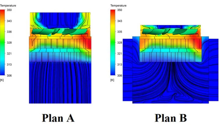
As can be seen from Figure 10, in the suction-type cooling system, the flow is substantially perpendicular to the heat exchanger surface due to the steady flow of the heat exchanger. Inside the cooling module, due to the different heat load of the heat exchanger, the cooling air produces distinct high temperature zones and low temperature zones, but does not mix in the cabin, thereby minimizing mutual interference between the heat exchangers.
Table 1. Radiator performance of different detached cooling compartments (2400r·min-1).
Calculation Schemes CAC resistance pCAC/Pa RAD resistance pRAD/Pa CAC Heat Exchange QCAC/kW RAD Heat Exchange QRAD/kW
Scheme A 182.1 230.0 30.6 41.5
Scheme B1 - 234.5 - 91.7
Scheme B2 - 263.4 - 97.1
Scheme B3 149.8 152.7 32.5 74.3
Scheme B4 164.1 142.6 38.6 69.2
Scheme B5 149.8 152.7 32.5 74.3
Table 1 shows the performance comparison of different non-series structure independent cooling modules. When the heat exchanger is arranged in a single form, the water radiator temperature is the ambient temperature, and there is no temperature rise after the cooling air passes through the CAC in the series scheme. Therefore, the heat exchange amount is obviously increased, and the same heat exchange requirement can be realized at a lower fan speed, and the fan power consumption is reduced. In addition, it is possible to achieve separate control of the temperature of the coolant by installing an electronically controlled louver at the front of the heat exchanger, thereby further improving the energy saving effect. In addition, it can be seen that the heat exchangers in the schemes B1 and B2 have the largest heat exchange capacity, but the flow resistance is also the largest. In order to analyze the input-output ratio between the fan power consumption and the heat exchanger heat exchange amount, evaluate the performance of the non-series structure independent cooling module and the series-connected series cooling module, define the cooling efficiency as the ratio of the total heat transfer amount Q of the heat exchanger to the pressure rise H of the fan. The comparison results are shown in Table 2.
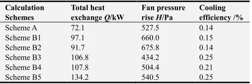
Table 2. Cooling efficiency of different detached cooling compartments (2400r•min-1).
Calculation Schemes Total heat exchange Q/kW Fan pressure rise H/Pa Cooling efficiency /%
Scheme A 72.1 527.5 0.14
Scheme B1 97.1 660.0 0.15
Scheme B2 91.7 675.8 0.14
Scheme B3 106.8 434.2 0.25
Scheme B4 107.8 504.4 0.21
Scheme B5 134.2 540.5 0.25
As can be seen from Table 2, Scheme A has the same cooling efficiency as Schemes B1 and B2 and is lower than Schemes B3, B4, and B5. It can be seen that if the heat exchanger is two or more, the non-series independent cooling module has a significant performance advantage. In addition, in the dual heat exchanger scheme, schemes B3 and B5 have higher cooling efficiency, and it can be seen that the different relative positions of the fan and the heat exchanger have a certain influence on the performance of the cooling module. Therefore, the multi-heat exchanger and its relative position, the relative angle with the fan will be the next research direction of the non-series independent cooling module.
5. Conclusion
When the independent cooling modules are arranged in a
series structure, the increase in the number of cooling air inlets is not significant for the performance improvement of the cooling module. When the independent cooling modules are arranged in a non-series configuration, the performance is improved significantly compared to the conventional series structure because the heat exchangers are relatively independent. However, the requirements for the installation space are also higher, and the relative position between the heat exchangers has an influence on its performance.
The dual heat exchanger non-series structure independent cooling module scheme has more advantages in performance than the single heat exchanger scheme and the series structure scheme, and has higher cooling efficiency. The independent cooling module can achieve the same heat dissipation requirement at a lower fan speed, reduce the fan power consumption, and can achieve precise cooling on the basis of the controllable blinds installed at the heat exchanger inlet to further improve the energy saving effect.
Acknowledgements
Project(51605430) supported by the National Natural Science Foundation of China; Project(LGG18E060001) supported by Zhejiang Public Welfare Technology Research Plan; Project(20170533B21, 20180533B10) supported by Self Declaration Project of Social Development Research in Hangzhou; Project(2018SCG204) supported by Zhejiang Province Educational Science Planning Research Topic; Project(Y201635880, Y201737460) supported by Scientific Research Projects of Zhejiang Province Education Department.
References
[1] Hai-Min Shi, Xiao-Li Yu, Yu-Qi Huang, et al. Shroud depth structure of multi-fans cooling package [J]. Zhejiang Daxue Xuebao (Gongxue Ban)/Journal of Zhejiang University (Engineering Science), 2017, 51(9): 1844-1850 and 1860. [2] Han Song, Lu Guodong. Intelligent engineering machinery
cooling system [P]. China, ZL200920116820.1. 2009-04-02. [3] Lu Feng, Yu Xiao-li, Lu Guo-dong. Experimental Study On
Effect of Encapsulation of Cooling Module for Diesel Engine [J]. Chinese Internal Combustion Engine Engineering, 2012, 33(003): 45-48.
[5] Haimin Shi, Xiaoli Yu, Guodong Lu, et al. An experimental study on energy-saving control of multi-fan cooling module [J]. Qiche Gongcheng/Automotive Engineering, 2017, 39(1): 102-106.
[6] Jörg Soldner, Werner Zobel, Michael Ehlers. A Compact Cooling System (CCS™): The Key to Meet Future Demands in Heavy Truck Cooling [C]. SAE Technical Paper, 2001, Paper Number: 2001-01-1709.
[7] Xueping Du, Min Zeng, Qiuwang Wang. Experimental investigation of heat transfer and resistance characteristics of a finned oval-tube heat exchanger with different air inlet angles [J]. Heat Transfer Engineering, 2014, 35(6-8): 703-710. [8] ANSYS FLUENT ANSYS. 14.5 User’s Guide [M]. ANSYS
Inc., 2014.
[9] Kays W M, London A L. Compact Heat Exchangers /-Third Edition [M]. McGraw-Hill Book Company, 1984.
[10] Ge J, Tian W, Qiu S, et al. CFD simulation of secondary side fluid flow and heat transfer of the passive residual heat removal heat exchanger [J]. Nuclear Engineering & Design, 2018, 337:27-37.
[11] Peng W, Li G, Geng J, et al. A strategy for the partition of MRF zones in axial fan simulation [J]. International Journal of Ventilation, 2018(5):1-15.
[12] Fan K, Wang Z, Ouyang S, et al. Change detection of remote sensing images through DT-CWT and MRF [J]. Journal of Remote Sensing, 2017, XLII-1/W1:3-10.
[13] Peter Gullberg, Lennart Löfdahl, Peter Nilsson. Continued Study of the Error and Consistency of Fan CFD MRF Models [J]. SAE, 2010, Paper Number: 2010-01-0553.
[14] Siswantara A I, Budiarso, Darmawan S. Investigation of Inverse-Turbulent-Prandtl Number with Four RNG k-ε Turbulence Models on Compressor Discharge Pipe of Bioenergy Micro Gas Turbine [J]. Applied Mechanics & Materials, 2016, 819:392-400.
[15] Budiarso, Siswantara A I, Darmawan S, et al. Inverse-Turbulent Prandtl Number Effects on Reynolds Numbers of RNG k-ε Turbulence Model on Cylindrical-Curved Pipe [J]. Applied Mechanics & Materials, 2015, 758:35-44.
[16] FU Jiahong, YU Xiaoli, LIU Zhentao, et al. Numerical study of flow and heat transfer on construction machinery detached vehicular cooling system [J]. Journal of Central South University (Science and Technology), 2016, 47(6):2119-2124. [17] FU Jiahong, YU Xiaoli, YAO Lingyu, et al. Numerical