Compression and Decompression of
Embedded System Codes
E.Silvia Helan1, Mr. P.M.Sandeep2, Mr.V.Suresh Babu3, Mr. M. Varatharaj4
1
Student, Department of ECE, Christ the King Engineering College, Anna University, Coimbatore, Tamilnadu - 641104, India.
2,3,4
Assistant Professor, Department of ECE, Christ the King Engineering College, Anna University, Coimbatore, Tamilnadu - 641104, India.
Abstract-Embedded system depends on three factors such as performance, power consumption and cost. Memory is a key factor in such systems. Code compression is a technique used in embedded system to reduce the memory usage .It has two methods such as Bit Mask code compression and dictionary based code compression. The Bit Mask code compression is to record mismatched values and their positions to reduce the greater number of instruction. In order to reduce the code word length of high frequency instruction Bit Mask algorithm is used. In addition, a novel dictionary selection algorithm was proposed to increase the instruction match rates. Compression ratio is placed in embedded system as a key factor for memory. The compression ratio is a metric used to evaluate memory compression efficiency (compressed code size divided by original code size).So, as a result it can achieve 7.5% improvement in the compression ratio. Furthermore, the code compression technique is used by Bit Mask compression, dictionary based code compression and Golomb coding.
Keywords--Computer architecture,
dictionary-based code compression (DCC), embedded systems, separated dictionaries
1. INTRODUCTION
EMBEDDED systems have become an essential part of everyday life, and are widely used worldwide. Embedded systems must be cost effective, and memory occupies a substantial portion of the entire system. To reduce the system cost, Wolfe and Chanin [1] first proposed code compression for compressing the program size in the early 1990s to conserve the memory usage. The compression ratio (CR) is a metric used to evaluate memory compression efficiency, which is defined as follows:
CR≡ Compressed Program Size+ Decoding Table
Original Program Size
To form a microcontroller the input and the output of the system has been integrated into the chip processor. The complexity and performance requirements for embedded programs grow rapidly, which results in additional memory usage and power consumption. For all the existing code compression techniques, compression is used to encode symbols into bit strings that use fewer bits. All binary instructions are compressed offline and decompressed as required during execution. Thus, to reduce the code size and to provide simple decompression engine are both challenges when applying code compression to embedded systems.
Dictionary-based code compression is commonly used in embedded systems, it can achieve an efficient CR, possess a relatively Simple decoding hardware, and provide a higher decompression ratio. Thus, it is suitable for architectures with high-bandwidth requirements, such as the very long instruction word (VLIW) processors. So, therefore no single compression has efficiently worked for different kinds of benchmarks. So, here various steps of code compression are combined into new algorithm to improve the compression performance in smaller hardware. Efficient bitmask selection technique that can create a large set of matching patterns. Based on the Bit Mask code compression (BCC) algorithm [3], [4], a small separated dictionary is proposed to restrict the code word length of high-frequency instructions, and a novel dictionary selection algorithm is proposed to achieve more satisfactory instruction selection, which in turn may reduce the average ratio. Furthermore, the separated dictionary architecture is proposed to improve the performance of the decompression engine. This architecture has a better chance to decompress the parallel instructions than existing single dictionary decoders.
II. CONVENTIONAL MODE
In this section, we briefly analyse the decompression hardware complexity of common variable-length compression techniques. This analysis forms the basis of our approach. Inthe following discussion, we use the term symbol to refer to a sequence of uncompressed bits and code to refer to a sequence of uncompressed bits and code to the compression result produced by the compression while compression efficiency is direct and widely used to evaluate compression techniques, the complexity of decompression determines the compression ratio.
Fig 1. Decoding the bitstream compression
Bitstream is compressed using dictionary based code compression and bitmask based code compression. The compressed bitstream is then generated using bitmask –based compression .The placement algorithm is employed to place the compressed bitstream in the memory for efficient decompression. During the runtime execution, the compressed bits are transmitted from the memory to the decompression engine, and the original bitstream is generated using decompression engine.
A. BITMASK ALGORITHMS
Lefurgy et al. Proposed the first dictionary-based method in 1999. Greedy methods have since been consistently used toconstruct the LUTs or dictionaries. The frequency distributionof instructions or instruction sequences is first calculated, and the instructions with the highest frequencies are inserted, inorder, into the LUT until the LUT is full. The instructions in the LUT are then encoded as dictionary indices. A tag bit(s) is used to determine whether the instruction is compressed by the LUT or not. Although the dictionary-based methods result in simpler decompression engines, their CRs are usually less efficient than those of other entropy-based compression algorithms. Thus, there have been
many modified versions of dictionary-based methods proposed to improve the CR. In this section, we introduce two kinds of BitMask methods, which are modified versions of the dictionary-based method. Bitmask is a pattern of binary values which is combined with some value using bitwise AND with the result that bit in the value in positions where the mask is zero and is set as zero. A bitmask is used to set certain bits using bitwise OR, or to invert them by using bitwise exclusive OR. Our compression technique also ensures that the decompression efficiency remains the same as compared to the previous techniques. Fig.1 shows a simplified example. The symbol sequences of A, B and G have been stored in the LUT, where G contains a 3-bit programmable field. For actual code compression, G is a branch instruction and the programmable field is the immediate part. Thus, the codeword will contain the programmed value .The purpose of Bitmask is used to cancel out some instructions. The symbol sequence AG and BG are compressible after the LUT has been created. A tag which is used to identify the codeword type and the following 3 bits are the operand parameter to program the programmable field of G. The last 3 bits are a bitmask and it is used to cancel out some instructions. For example, if the bitmask is set to 101, the decompression engine will cancel out symbol B during decompression. So, the mask is a data that is used for bitwise operations, particularly in a bit field.
Fig.2.Bitmask-based method
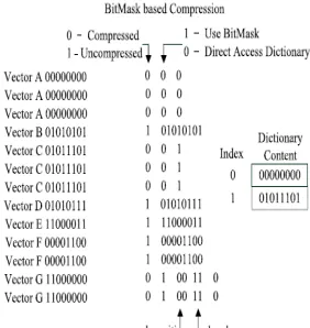
B. DICTIONARY SELECTION ALGORITHM
with a code word so the index of the dictionary contains a pattern. The compressed program consists of both code words and uncompressed data.Fig.3 shows an example of dictionary based code compression using a simple binary program .The binary bit consists of ten 8 bit patterns, i.e., a total of 80 bit. The compressed bitstreams requires 62 b, and the dictionary requires 16 b. In this case, the CR is 97.5% .The bitstream CR for dictionary selection is large therefore it does not yield a fast compression ratio .Therefore, the bitstreams cannot be compressed using dictionary code compression but it can be compressed using bitmask selection which yields a smaller compression ratio.
Fig.3. Bitstream compression using dictionary selection
III. PROPOSED SYSTEM
A.GOLOMB CODING
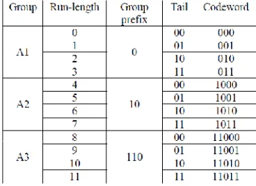
Golomb coding is a lossless data compression technique. It is used to compress the larger sized data into smaller sized data and still allowing the original data to be reconstructed back after decompression. Besides, there is other high performance lossless compression algorithm.This algorithm involves higher design complexity and computational load. In lossy data compression, the reconstructed data loses some of the information this result in lower quality data. In Golomb Coding, the group size, m, defines the code structure. Thus, choosing the m parameter decides variable length code structure and it has direct impact on the compression efficiency. Once the parameter m is decided, a table chooses to run with zeros until the code is ended with a one and is created by one. Determination of the run length is shown as in Fig 3. A run length of m are grouped into AK and given the same prefix, which is (k – 1) number of ones followed by a zero. A tail is given to the group members, which is the binary representation of zero until (m – 1). The codeword is then produced by combining the prefix and tail. In Fig 4. The binary strings are divided into subset of binary strings.
Fig.3: Determination of Run length
Fig .4: Golomb coding example with parameter m=4
Fig 5. shows the encoded data is produced by combining the group prefix and tail.
Fig.5:Encoded data with parameter m=4
The Golomb encoder model can be described in the flow chart as shown in Fig 6. The tail count is controlled by the number of ‘0’s in the input data. If the ‘0’s are read, then the tail count will be increased proportionally until it reaches the
m parameter, where ‘1’ is generated at its output data. If the input data is‘1’, the algorithm will generate a ‘0’ which acts as a divider between the prefix and the tail, and it output the current tail count as the encoded string. The algorithm will then reset the tail count and waits for the next input data. The Golomb decoder model can be described in the flow chart as in Fig 7. The system first detect the values of prefix, if it is ‘1’, then the system will generate 4 ‘0’s and waits for the next value. If ‘0’ is detected, then the system will acknowledge that the end of prefix has been met and first tail bit will be detected. If the value of the first tail bit is ‘1’, the system will generate another 2 ‘0’s and waits for the next tail bit. If the last tail bit is ‘1’, another extra ‘0’ will be generated and followed by a ‘1’ which will be marked at the end of a subgroup of original data. The system will then return to the status of waiting for the next subgroupprefix data.
Fig.7.Golomb decoder algorithm
A. DECOMPRESSION ENGINE
Fig.8: Decompression Engine
The decompression engine is a hardware component used to reconfigure a compressed bitstream, the resourceusage and maximum operating frequency. A decompression engine has the buffering circuitry which is used to buffer and align codes will fetch from the memory, while decoders performs decompression operation to generate original codes. The design of a decompression engine, shown in Fig.3 can easily handle bit masks and provide fast decompression. The feature of decompression engine is the introduction of XOR gate. Thedecompression engine generates a test data length bitmask, which is XORed with the dictionary entry. The test data length bit mask is created by applying the bitmask on the specified position in the encoding. The generation of bit mask is done in parallel with dictionary access, thus reducing additional penalty. The DCE can decode more than one compressed data in one cycle. The compressed vector takes input to decompression engine. Further it checks the first bit to see whether the data is compressed or not. If the first bit is “1” (implies uncompressed), it directly sends the uncompressed data to the output buffer.On the other, if the first bit is a “0”, then it is compressed data. Now, there are two possibilities. The data may be compressed directly using dictionary selection or may be by using bit masks.
IV. CONCLUSION
Fig.9Bitmask selection and dictionary selection compression technique
Fig.10 Decompressed method of Bitmask selection and Dictionary selection
Fig.12: Decompressed Golomb coding
PARAMETERS BITMASK AND DICTIONARY BASED COMPRESSION
GOLOMB CODING
CR
0.508 0.383POWER
386mW 341mWAREA
9.079 6.916Fig.11: Comparison ofthe LUT Tabl
V. REFERENCE
1. Wei Jhih Wang and Chang Hong Lin, “Code Compression for Embedded Systems Using Separated Dictionaries,’’ IEEE Transaction on very large scale integration (VLSI) Systems, Vol. 24, NO. 1, Jan. 2016. 2. Wolfe and A. Chanin, “Executing compressed programs on an embedded RISC architecture,” in Proc.
25th Annu. Int. Symp.Microarchitecture, Dec. 1992,
pp. 81–91.
3. Lefurgy, P. Bird, I.-C. Chen, and T. Mudge, “Improving code density using compression techniques,” in Proc. 30th Annu. ACM/IEEE Int.Symp.
MICRO, Dec. 1997, pp. 194–203.
4. S.-W. Seong and P. Mishra, “A bitmask-based code compression technique for embedded systems,” in
Proc. IEEE/ACM ICCAD, Nov. 2006, pp. 251–254.
5. S.-W. Seong and P. Mishra, “An efficient code compression technique using application-aware bitmask and dictionary selection methods,” in Proc. DATE, 2007, pp. 1–6.
6. H. Lekatsas and W. Wolf, “SAMC: A code compression algorithm for embedded processors,”
IEEE Trans. Computer-Aided Design Integr.Circuits
Syst., vol. 18, no. 12, pp. 1689–1701, Dec. 1999.
7. S. Y. Larin and T. M. Conte, “Compiler-driven cached code compression schemes for embedded ILP
processors,” in Proc. 32nd Annu. Int.
Symp.Microarchitecture, Nov. 1999, pp. 82–91.
8. Y. Xie, W. Wolf, and H. Lekatsas, “Code compression for VLIW processors using variable-to-fixed coding,”
in Proc. 15th ISSS, 2002, pp. 138–143.
9. H. Lin, Y. Xie, and W. Wolf, “Code compression for VLIW embedded systems using a self-generating table,” IEEE Trans. Very Large ScaleIntegr. (VLSI)
Syst., vol. 15, no. 10, pp. 1160–1171, Oct. 2007.
10. C.-W. Lin, C. H. Lin, and W. J. Wang, “A Power-aware code compression design for RISC/VLIW architecture,” J. Zhejiang Univ.-Sci.C (Comput.