© 2017 IJSRST | Volume 3 | Issue 8 | Print ISSN: 2395-6011 | Online ISSN: 2395-602X Themed Section: Science and Technology
Design of LabVIEW Based SCADA System for Pneumatics Applications
Rathy G. A1, Aravind Balaji2
1Associate Professor, Electrical Department, NITTTR, Chennai, India 2R&D Engineer, Bharathi Enterprises, Chennai, India
ABSTRACT
SCADA is the acronym for Supervisory Control And Data Acquisition. The term SCADA refers to a central system that monitors and controls a complete site. The Human Machine Interface (HMI) /SCADA industry was essentially born out of a need for a user-friendly front-end to a control system containing controllers like programmable logic controllers (PLC) Propotional Integral Derivative Controllers(PID) etc. The SCADA system usually presents the information to the operating personnel in the form of a mimic. This means that the operator can see a representation of the plant being controlled. Also data can be logged in to the system.
LabVIEW - Laboratory Virtual Instrument Engineering Workbench. LabVIEW is graphical programming for
measurement and automation. It is a development tool available for applications in test and measurement. LabVIEW enables easy data acquisition, instrument control, and industrial automation.This paper discusses a novel idea to develop a SCADA system for pneumatic applications using user friendly software like LABVIEW and low cost field serviceable Human Machine Interface that is a Personal Computer.
Keywords:
SCADA, LabVIEW, Datalogging and Supervisory Control(DSC) module, myDAC, pneumatic valve
and double acting cylinder
I.
INTRODUCTION
SCADA (supervisory control and data acquisition) is a type of Industrial Control System (ICS). Industrial control systems are computer controlled systems that monitor and control industrial processes that exist in the physical world. The SCADA system will function as the front end and the controller will serve as the back end from where data are collected and displayed in the SCADA screens. In this paper it is proposed to use the LabVIEW software as the front end and using the real time device myDAC data can be collected and displayed in SCADA Screens.
II.
LITERATURE REVIEW
SCADA sysyems have been developed using LabVIEW and different types of controllers as described in the
Review of Literature
Pooja Panchal,Alpesh Patel, Jayesh Barve (2015) developed a PID controller using PLC for a single tank level control system. Using NI-LabVIEW, a SCADA platform has been developed to monitor the system and log the real-time process data. MODBUS RTU
communication protocol has been used for exchange of real-time process parameters between PLC and NI-LabVIEW.
Avinash P. Kaldate and Sachin A. Kulkarni (2014) have conducted a study on microcontroller (PIC16) and LabVIEW based SCADA system for monitoring & accessing the performance by acquiring and controlling the physical parameters such as Temperature, Humidity, Soil moisture and intensity of light of green house system on a real time basis. Using software like LabVIEW along with a low cost microcontroller (PIC16) based data acquisition hardware as DAQ card the real time monitoring of physical parameters can be acquired and saved into database files like MSExcel or other format and can be communicated with other PC.
using a (IBH) OPC server and SCADA application development using LABVIEW installed in personal computer which can realize more than the intended result.
Slobodan Aleksandrov (2011) SCADA system for controlling and monitoring mechatronic systems which are controlled by programmable logical controllers (PLC) and connected into local area network (LAN). Application OPC Easy Server is used to access PLC, software package LabView is used to create graphical control environment.
This paper focuses on developing SCADA screens for pneumatic applications using the DSC module present in Labview and real time interfacing is done using myDAQ.
III.
SCADA SYSTEM
A SCADA system consists of a Master terminal unit (a computer), number of remote terminal units (RTUs) collecting field data and sending that data back to a master station, via a communication system. The master station displays the acquired data and allows the operator to perform remote control tasks. The accurate and timely data allows for optimization of the plant operation and process. The main advantages of the system are efficiency, reliability and safer operations. This result in a lower cost of operation compared to earlier non-automated systems.
Four levels of SCADA system
Level I – Field Devices: RTUs / PLCs &Sensors
Level II – Telecommunication Fiber, Radio, Telephone, leased line & Protocols
Level III – SCADA / MTU Operator Workstations, Control, Engineering Workstations, Servers – Data logging
Level IV – Enterprise Corporate LAN/WAN, World Wide Web, Virtual Private Network, Firewall for remote users.
SCADA finds its applications in Power plants,Railways,Wind Energy Systems,Process Control
Industries,Automotive Industries
The three basic types of SCADA systems are
Basic SCADA
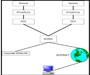
As shown in Fig 1. Basic SCADA system has one machine process. It comprises of one RTU and one MTU. Examples areCar manufacturing robot, Room temperature control
Figure 1: Basic SCADA System
Integrated SCADA
It comprises of Multiple RTUs and Distributed Control Systems(DCS). Fig 2. Shows the diagram of Integrated SCADA system
Figure 2 : Integrated SCADA system
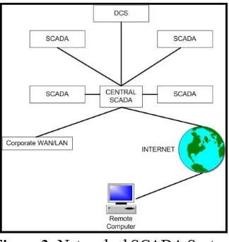
Networked SCADA
Figure 3 :Networked SCADA System
Multiple SCADA are linked to the Central scada and through internet it is connected to a remote computer
IV.
LABVIEW
LABVIEW Software can be used to develop screens which can be interfaced with real time applications. LABVIEW programs/subroutines are called virtual instruments (VIs). Each VI has three components: a block diagram, a front panel, and a connector panel. Controls and indicators on the front panel allow an operator to input data into or extract data from a running virtual instrument. Thus a virtual instrument can either be run as a program, with the front panel serving as a user interface. The block diagram represents the code for the front panel. The programming language used in LABVIEW, also referred to as G, is a dataflow programming language. The blocks are connected through wires and data flow takes place from left to right.
NI myDAQ Hardware
NI myDAQ is a low-cost portable data acquisition (DAQ) device that uses NI Lab VIEW-based software instruments, allowing us to measure and analyze real- world signals. NI myDAQ as shown in Fig 4 is ideal for exploring electronics and taking sensor measurements. Combined with NI Lab VIEW on the PC, it is possible to analyze and process acquired signals and control simple processes anytime, anywhere.
Figure 4 : NI myDAQ
NI myDAQ provides analog input (AI), analog output (AO), digital input and output (DIO), audio, power supplies, and digital multimeter (DMM) functions in a compact USB device.
Analog Input (AI): In NI myDAQ, there are two analog input channels. The analog input channels can be configured either as general-purpose high-impedance differential voltage input or audio input. These inputs are multiplexed; which means that single analog-to-digital converter (ADC) is used to sample both channels.
Analog Output (AO): In NI myDAQ, there are two analog output channels. The output channels can be configured as either general-purpose voltage output or audio output. Both channels have a dedicated digital-to-analog converter (DAC), so they can update simultaneously.
Digital Input/output (DIO): In NI myDAQ, there are eight DIO lines. Each line is a Programmable Function Interface (PFI), which means that configures as a general-purpose software-timed digital input or output, or it can act as a special function input or output for a digital counter. The input—accessed through DIO 0, DIO 1, and DIO 2 signals can be configured as a counter which is used for counter, timer, pulse width measuring, and quadrature encoder applications
Digital Multimeter (DMM): The NI myDAQ DMM provides the functions for measuring voltage (DC and AC), current (DC and AC), resistance, and diode voltage drop
V.
PNEUMATICS
Pneumatics is working with a system that uses the force of gas, usually air to do work (Hutchinson and Karsnitz 1994).It is used widely in applications such as dentists drills, automatic doors, brakes on lorries and hammer drills used at roadworkand mainly in the field of automation.
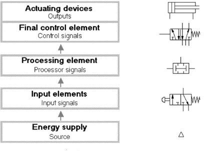
Figure 5: Pneumatic system structure and signal flow.
Fig 5. shows the pneumatic system structure and signal flow. The compressed air is the source and this passes through the input element, the processing element ,the finite control element and finally energises the actuating devices
Drive Elements are Actuating devices used to perform the task of exerting the required force at the end of the stroke or used to create displacement by the movement of the piston
These pneumatic components are modeled in LABVIEW as SCADA screens and the same are controlled through myDAC.Fig 6. Shows the symbol of pneumatic components
Figure 6. Symbol of pneumatic components a single acting cylinder b.double acting cylinder c. 5 port valve d. shuttle valve.
VI.
IMPLEMENTATION OF SCADA IN
LABVIEW
SCADA can be implemented in Labview using Data logging and Supervisory Control (DSC) Module. The DSC Module extends graphical programming benefits to the development of SCADA or high-channel-count data-logging applications. The tools are used to communicate to conventional programmable logic controllers (PLCs) and programmable automation controllers (PACs), log data to databases, manage alarms and events, and create human machine interfaces (HMIs) and data acquisition card.
switches and FRL control. This can be achieved by editing the controls and indicators in labview by replacing the graphical images of the controls and indicator with the desired images. Images can be imported either using DSC module or directly while editing the controls .To determine the operation of the double acting cylinder it can be either simulated or used as an control to control the external setup, by selecting the desired operation in the menu. It can either be simulated and also control by interfacing the external setup with labview using myDAQ by configuring the desired digital inputs and outputs.
Figure 7. Front panel implementation
Operation:
The operation pallet is used to select the desired operation
It has three option:1. Reset 2.Automatic operation of double acting cylinder 3. Simulation . Reset is used to reset the entire application and hardware and bring them back to initial condition. Automatic operation of double acting cylinder is used to control the pneumatic trainer kit using the application; it is controlled depending upon the sequence selected in the sequence pallet.Sequence is used to select the desired sequence in which the pneumatic kit is to be operated it has five options: A.1st cycle
It operates the double acting cylinder for one cycle (piston moves forward and reverse once)
B.Delay cycle
It operates the double acting cylinder depending upon the delay given in the millisecond to wait pallet(eg: if 1000 is give in the millisecond to wait pallet the piston move to and fro with a delay of 1 second).
C. N cycle
It is used to operate the double acting cylinder depending upon the no of cycle given in the pallet(eg: if 3 is given in the pallet then the piston moves to and fro 3 times).
D. Multicycle
It is used to operate the double acting cylinder continuously.
E.Two cylinder
It is used to operate two double acting cylinder at a time.
Simulation
Simulation is used to show the virtual double acting cylinder available in the vi, depending upon the option selected in the simulation pallet.
Home position:
It is used to set the double acting cylinder to the home position.
Simulation sequence:
Simulation sequence pallet is used to select the operation to be simulated. It has three options:1.Manual 2.Single sequencial cycle 3.Sequencial cycle
Manual:
It is used to control the simulation of the double acting cylinder manually controlling the solenoid coils using the switches in the solenoid coils. The piston moves forward or reverse depending upon the switch pressed.
Single sequential cycle:
It is used to simulate the double acting cylinder for one cycle (the piston moves to and fro once).
Sequential cycle:
Figure 8. Block diagram implementation
By selecting the appropriate menu the desired conditions are been selected using switch case function. The double acting cylinder can be operated for single cycle or multiple cycle by selecting the no of cycle the fig 8 shows the block diagram for single cycle sequence, buttons are provided for home position to come back to normal position.Similarly the hardware implementation are been down using myDAQ by configuring the digital inputs and outputs, limit switch are been used to determine the current position of the shaft which is been given as the input to the mydaq and the solenoid coil are been energized using relay to move the shaft forward and reverse. Depending upon the limit switch output the forward and reverse action are been performed.
The fig.9 shows the hardware control using LabVIEW, Automatic operation of double acting cylinder under the operation manual and the external setup is interfaced to LabVIEW using myDAQ and the forward and reverse solenoid coil are controlled by pressing the forward and reverse switch in the LabVIEW. The forward and reverse coil are been energized by digital output from the myDAQ using relay as shown in the below diagram
Figure 9. Hardware Setup
VII.
Result
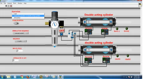
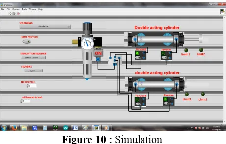
The fig 10 shows the output of the simulation it can be implemented by selecting the simulation menu under operation pallet the by clicking the on button in the FRL. The process starts and the double acting cylinder moves to and fro depending upon the limit switch indication.
Figure 10 : Simulation
The fig.11 give below shows the hardware control using labview, Automatic operation of double acting cylinder under the operation manual and the external setup has been interfaced with LabVIEW using myDAQ and the forward and reverse solenoid coil are controlled by pressing the forward and reverse switch in the labview. This has been interfaced with the actual experimental setup.
Figure 11 : Hardware Control
VIII.
CONCLUSION
is possible to simulate and control the working of the double acting cylinder both in the software and also in the pneumatic controller kit
IX.
REFERENCES
[1]. Jeffrey Travis, Jim Kring,(2006) " lab VIEW for Everyone: Graphical Programming Made Easy and Fun", Prentice Hall.
[2]. Pooja Panchal,Alpesh Patel, Jayesh Barve,(2015) "PI control of level control system using PLC and Lab VIEW based SCADA" published at the International Conference on Industrial Instrumentation and Control (ICIC)Year: 2015Pages: 1196 - 1201
[3]. Nishantkumar D. Gajipara, Prashant L. Ahire (2014) "Design of SCADA for Real Time System with LabVIEW and Microcontroller" published in the International Journal of Innovative Research in Advanced Engineering (IJIRAE) ISSN: 2349-2163 Volume 1 Issue 7 (August 2014)
[4]. Somasundaram B et.al (2013) "SCADA Application Development Using LABVIEW" published in the International Journal of Engineering and Innovative Technology (IJEIT) Volume 3, Issue 2, August 2013. ISSN: 2277-3754
[5]. Slobodan Aleksandrov (2011) "Mechatronic Systems Control Based On Scada System, OPC Server And Labview" FACTA UNIVERSITATIS Series: Automatic Control and Robotics Vol. 10, No 2, 2011, pp. 189 – 198
[6]. NI myDAQ User guide www.ni.com/pdf/manuals/373060f.pdf
[7]. LabVIEW Graphical Programming by Gary W. Johnson and Richard Jennings, Fourth Edition, McGraw Hill Education (India) Private Limited [8]. Jovitha Jerome(2013) Virtual Instrumentation
Using LabVIEW by, 2nd Edition, PHI Learning Private Limited.