International Journal of Advanced Technology in Engineering and Science www.ijates.com Volume No 03, Special Issue No. 01, March 2015 ISSN (online): 2348 – 7550
605 |
P a g e
FESA: FUZZY CONTROLLED ENERGY EFFICIENT
SELECTIVE ALLOCATION AND REALLOCATION
OF TASKS AMONG MOBILE ROBOTS
Dr. Anuradha Banerjee
Dept of Computer Applications, Kalyani Govt. Engg. College ,West Bengal.(India)
ABSTRACT
Energy aware operation is one of the visionary goals in the area of robotics because operability of robots is
greatly dependent upon their residual energy. Practically, the tasks allocated to robots carry different priority
and often an upper limit of timestamp is imposed within which the task needs to be completed. If a robot is
unable to complete one particular task given to it the task is reallocated to some other robot. The collection of
robots is controlled by a Central Monitoring Unit (CMU). Selection of the new robot is performed by a fuzzy
controller called Task Reallocator (TRAC). It accepts the parameters like residual energy of robots, possibility
that the task will be successfully completed by the new robot within stipulated time, distance of the new robot
(where the task is reallocated) from distance of the old one (where the task was going on) etc. The proposed
methodology increases the probability of completing globally assigned tasks and saves huge amount of energy
as far as the collection of robots is concerned.
Keywords: Energy efficiency, Fuzzy Controller, Priority, Selection, Task.
I.
INTRODUCTION
The present article focuses on the efficient distribution of tasks among a collection of mobile robots, which are centrally controlled by a Central Monitoring Unit (CMU). All robots can directly send signals to CMU and receive signals from it. The situation can be detected from figure 1 where R, R1, R2 and R3 are the robots. CMU keeps track of the residual energy of robots, tasks that are allocated to them and the present status of execution of those tasks along with the constraints associated with them. A decision process is initiated in order to accept/ reject tasks for further processing as well as to continue/ re-allocate a task in progress. On a global point of view, a task allocation procedure is initiated after arrival of a new job or cancellation of an ongoing task subjected to the availability of able robots.
International Journal of Advanced Technology in Engineering and Science www.ijates.com Volume No 03, Special Issue No. 01, March 2015 ISSN (online): 2348 – 7550
606 |
P a g e
mechanism is presented whereby all robots have the same threshold and the differentiation comes from the variability in the local observation of the signal intensity by the individuals. In [8] an ant-like task allocation model was proposed that is based on local threshold value for energy efficiency.The rest of the paper is organized as follows. Section 2 illustrates the basic system model. Heuristics that drive TRAC are discussed in section 3. Design of TRAC is performed in section 4. Section 5 emphasizes the effectiveness of our proposed scheme through extensive simulation results. Section 6 analyzes the complexity of our proposed scheme FESA and section 7 concludes the paper.
Fig.1 Signal transmission and reception between CMU and robots R, R1, R2 and R3
1.1 System Model of FESA
The system of FESA consists of a collection of robots and a CMU that allocates and reallocates the tasks to robots as the tasks arrive into the system. The system is non-preemptive. Once a task is allocated to a robot, say R1, it is allowed to continue its task till the upper limit of time duration associated with the task elapses or some unnatural incident makes R1 unable to operate any further. For example, fire may break out into the system and destroy R1. It may be noted that, at any point of time a task may be allocated to exactly one robot. When a new task arrives into the system it is initially allocated to any idle robot possessing sufficient amount of energy to complete the task. If no such robot is found, then the task is allocated to one of the robots having maximum residual energy. The intention is to complete a task as much as possible. On the other hand, during reallocation, CMU consults the TRAC embedded in it to find the best possible robot to carry out the pending task. A task is reallocated if sufficient time is there to complete the task i.e. upper limit of timestamp within which the task needs to be completed, is not crossed, at least one operational idle robot is there and no task with higher priority is waiting at that time for being allocated or reallocated to robots. CMU maintains three different tables termed as ROBOT_TABLE, TASK_TABLE and HISTORY_TABLE. CMU also stores the maximum possible distance between any two robots through a path traversable in the present geographical scenario. Attributes of the mentioned tables are shown below:
ROBOT_TABLE HISTORY_TABLE
Robot_id Robot_id
Enrg_tot Task_id
Enrg_thres Task_portion
Session_id
Assign_timestamp Release_timestamp
TASK_TABLE
Task_id Priority
Completion_timestamp R
R1
CMU
International Journal of Advanced Technology in Engineering and Science www.ijates.com Volume No 03, Special Issue No. 01, March 2015 ISSN (online): 2348 – 7550
607 |
P a g e
Ptr_robotarrayEnrg_task Enrg_rem_task Status
A tuple (p,q,r) in the ROBOT_TABLE indicates that p is identification number of one robot, q is its total energy and r is its energy threshold. According to the characteristic curve of the batteries used in mobile robots, voltage drop shows a linear decline until some critical value [1, 2]. After that point the voltage drop speeds up quickly with very small remaining time left for execution [1]. Energy of the robot corresponding to the critical voltage is termed as energy threshold of the robot.
A tuple (p, ts, tp, sid, atm, rtm) in the HISTORY_TABLE signifies that the robot p completed tp portion of the task ts within time interval (rtm-atm) in session sid. atm is the timestamp at which the task was assigned and rtm is the time at which the task finished. Similarly, a tuple (ts, pr, ct, rbr, et, etrem, st) in TASK_TABLE denotes that the task with identification number ts has priority pr and it needs to be completed within timestamp ct. rbr is pointer to a list. Each entry of the list contains identification numbers of the robots to which the task was assigned earlier, portion of the task that was assigned along with the corresponding timestamp, the timestamp when the robot unsuccessfully stopped execution of that portion of the task and portion of the task remaining to be executed. et is the minimum energy required to accomplish the whole task whereas etrem is the minimum energy required to accomplish the remaining portion of the task. All possible values of st are 0 and 1. It is set to 0 if the task is being executed and set to 1 if it cannot be completed (possible reasons are unavailability of robots, completion time constraints etc.).
During reallocation, portion of a task may be reallocated. For example, let 50% of a task has been carried out by a robot R1 after which it suddenly stopped operating. Then the rest 50% of the same work can be allocated to some other robot R2 although it is not possible in our proposed scheme to allocate 30% of the remaining task to R2 and the rest to R3, simultaneously. At any point of time, one particular task cannot run in more than one robot, even partly.
1.2 Heuristics of TRAC
The fuzzy controller TRAC, which is responsible for task reallocation, performs according to the following heuristics:
i) If a robot R is equipped with high residual battery power so that the residual energy above its energy threshold is greater than the energy required to accomplish the remaining portion of task A, then R is in an advantageous position to execute that portion of the task.
ii) According to the HISTORY_TABLE of CMU, if a robot R has successfully accomplished the task A earlier within the mentioned stipulated time duration, then R has a good chance of being assigned the same task A in future.
iii) If the minimum geographical distance through a traversable region within the given scenario, of the old robot R1 (where a task A was going on earlier) from the new robot R (where A is going to be reallocated) is small, then it will be beneficial for the new robot R to resume the task, specially when the task is of the type exploration and supervision of unknown surroundings.
International Journal of Advanced Technology in Engineering and Science www.ijates.com Volume No 03, Special Issue No. 01, March 2015 ISSN (online): 2348 – 7550
608 |
P a g e
occasions, then it is better to avoid R during reallocation of tasks.The observations expressed above are in the form of if-then rules which are the basic unit of fuzzy function approximation. Advantages of fuzzy logic are that it is flexible, conceptually easy to understand and based on natural language. Moreover, it is tolerant of imprecise data and can model non-linear functions of arbitrary complexity. All these encouraged us to design the scheme of FESA using fuzzy logic.
II.
DESIGN
OF
TRAC
2.1 Formulation of parameters
The input parameters of TRAC are energy_efficiency, history_of_support, distance_quotient and failure_quotient. These are formulated below based on the assumption that the current timestamp is t and TRAC
is considering to reallocate a portion (A,t) of task A in robot R. R1 is the old robot where the task A was being carried out.
Energy_efficiency
The energy_efficiency R(t) of a robot R at time t is given by, R(t)=1–eA/(ER(t)–EthresR) (1)
eA specifies the minimum energy required to complete portion of the task A to be reallocated. ER(t) is the residual energy of robot R at time t and EthresR signifies the threshold energy of the same robot. It is quite
evident from (1) that R(t) lies between - and 1. Positive fractional values of R(t) puts R in a good position to
carry out the task (A,t).
History_of_support
Let H(R,A) denote the set of occasions or sessions during which the robot R successfully completed execution of the portion of task A that was given to it abiding by the time constraint associated with the task. Also assume that HF(R,A) denote the set of occasions or sessions during which the robot R could not successfully complete execution of the portion of task A that was given to it. Then, history_of_support hR,A(t) of robot R at time t with respect to task A is given by,
(h R,A(t) / T_C(A)) if (h R,A(t) / T_C(A)) 1
hR,A(t) = (2)
(h R,A(t) / T_C(A)) exp Z(R,A) otherwise
hR,A(t) = [{t+{ (R,w/qw(A))}1/|H(R,A)|}(A,t)] (3) wH(R,A)
Z(R,A) = H(R,A) / {H(R,A)+HF(R,A)}
According to the history of behavior of robot R, in session w, qw(A) portion of the task A has been completed by
robot R in time duration R,w. T_C(A) is the timestamp within which the task A must be fully completed. If
International Journal of Advanced Technology in Engineering and Science www.ijates.com Volume No 03, Special Issue No. 01, March 2015 ISSN (online): 2348 – 7550
609 |
P a g e
if number of successes of robot R with respect to task A is high and number of failures of R with respect to task A is low, i.e. if H(R,A) is high and HF(R,A). This is correctly modeled through Z(R,A).Distance_quotient
Let distR,R1(t) be the least geographical distance between the robots R1 and R at time t through a path which is traversable in the present scenario. Also assume that dist_max is the maximum possible distance between any two robots through a path traversable in the present scenario. Then, the distance_quotient dqR,R1(t) of robot R w.r.t. robot R1 at time t is given by,
dqR,R1(t) = distR,R1(t) / dist_max (4)
Distance_quotient lies between 0 and 1. Values close to 0 indicate that R won’t have to make huge extra efforts
to resume the pending task A of R1.
Failure_quotient
Let R(t) be the number of tasks allocated to robot R within time t, irrespective of whether they were allocated
fully or partly. Among them, on R(t) number of occasions the tasks had to be reallocated from R. Hence, the failure quotient fqR(t) of robot R at time t based on the history of it’s behavior, is,
fqR(t) = R(t) / R(t) (5)
Actually failure quotient of a robot indicates its general attitude towards the tasks assigned to it by the CMU. If it is high then it denotes that R is only eager to relinquish its tasks. Please note that fq also ranges between 0 and 1.
2.2 Rule Bases of TRAC
As far as the range division of is concerned, the range from - to 0 is not advantageous for the system and it is denoted as a1. The ranges from 0-0.33, 0.33-0.66, 0.66-1 are indicated as a2, a3 and a4 respectively. For range division of h, the ranges from 0-0.33, 0.33-0.66, 0.66-1 are indicated as a1, a2 and a3 respectively. The
range from 1- is not acceptable and it is denoted as a4. For the subsequent two parameters dq and fq the range division is uniform between 0 and 1, i.e. 0-0.25 is a1, 0.25-0.50 is a2, 0.50-0.75 is a3 and 0.75-1 as a4. Please note that the subscripts have been omitted here for simplicity.
International Journal of Advanced Technology in Engineering and Science www.ijates.com Volume No 03, Special Issue No. 01, March 2015 ISSN (online): 2348 – 7550
610 |
P a g e
Table.1. Fuzzy Combination of and h Generating t1 h
a1 a2 a3 a4
a1 a1 a2 a3 a4
a2 a1 a2 a3 a4
a3 a1 a2 a2 a3
a4 a1 a1 a1 a2
Table.2. Fuzzy Combination of t1 and fq Generating t2 t1
fq
a1 a2 a3 a4
a1 a1 a2 a3 a4
a2 a1 a2 a3 a4
a3 a1 a2 a3 a3
a4 a1 a1 a2 a3
Table.3. Fuzzy Combination of t2 and dq Generating reloc t2
dq
a1 a2 a3 a4
a1 a1 a2 a3 a4
a2 a1 a2 a3 a4
a3 a1 a2 a3 a4
a4 a1 a2 a2 a3
Among the various value ranges of reloc of different robots, any one possessing the highest value range will be selected for reallocation of a certain job.
III.
SIMULATION
RESULTS
For simulation, I have used the Webots 3D physics-based robotics simulator [9] to create the virtual world which the robots mapped and navigated as part of the experiments. Webots has high fidelity and models realistic sensor and motion errors. In the simulation experiments I used RV-400 [10] robots. In various runs, the number of robots was 3, 6, 9, 11 and 14 while the number of tasks was 5, 9, 12, 15 and 20. The tasks are to explore portions of a room of different sizes. The simulation was carried out for approximately 3000 seconds. The results reported graphically in this section correspond to the average of all the simulation runs.
International Journal of Advanced Technology in Engineering and Science www.ijates.com Volume No 03, Special Issue No. 01, March 2015 ISSN (online): 2348 – 7550
611 |
P a g e
Cons um e d e ne rgy pe r robot vs num be r of tas k s
0 200 400 600 800 1000
5 9 12 15 20 Num be r of tas k s
C o n su m ed e n er g y p er ro b o t EOTA ATA FESA
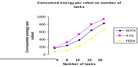
Figure 2: Graphical illustration of consumed energy in Joule per robot vs number of tasks
Pe rce ntage of s ucce s s fully com ple te d tas k s vs num be r of tas k s
75 80 85 90 95 100 105
5 9 12 15 20 Num be r of tas k s
P er ce n ta g e o f su cc es sf u lly co m p le te d t as ks EOTA ATA FESA
Figure 3: Graphical illustration of percentage of
successfully completed tasks vs number of
tasks
De lay for com ple tion of e ach tas k vs num be r of tas k s
0 20 40 60 80 100 120 140 160
5 9 12 15 20 Num be r of tas k s
D el ay fo r c om pl et io n of ea ch ta sk EOTA ATA FESA
Figure 4: Graphical illustration of delay for completion of each task in seconds vs number of
tasks
Pe rce ntage of re allocate d tas k s vs num be r of tas k s
0 5 10 15 20 25 30 35 40
5 9 12 15 20 Num be r of tas k s
P er ce n ta g e o f re al lo ca te d ta sk s EOTA ATA FESA
International Journal of Advanced Technology in Engineering and Science www.ijates.com Volume No 03, Special Issue No. 01, March 2015 ISSN (online): 2348 – 7550
612 |
P a g e
If a robot is bound to execute some task when its residual energy is less than energy threshold, then its rate of energy consumption abruptly increases. Our proposed scheme FESA always tries to allocate or reallocate tasks to those robots that have sufficient battery power to execute the tasks. Moreover, during reallocation, FESA tries to find new robots which are geographically close to the old one so that the new robot chosen by TRAC can efficiently take over the charge of the old one without much effort. This is particularly useful for the tasks like exploring a room. All these contribute to the reduction of energy consumption in favor of our proposed scheme FESA. However, it is quite trivial that the amount of energy consumption for each robot will increase for all the task allocation schemes as the number of tasks increase. This is illustrated in figure 2.By analyzing the attitude of robots towards a specific task and to all other tasks from the task table in CMU, preferences are given to the robots which have successfully completed the same task or its portion, whatever was assigned to it, within specific time limit. Also the robots that have shown a positive response to the tasks assigned to them in general, obtain more weight than others. Reallocating tasks to these robots improve the chance of successful completion of a task. Hence, percentage of successfully completed tasks increase along with the decrease in the percentage of reallocated tasks. These are evident from figures 3 and 5. As the number of tasks become huge, percentage of successfully completed tasks decrease (and percentage of reallocated tasks increase) for all the task allocation schemes have been compared here. The reason is possible unavailability of robots with sufficient energy or priority collision among the tasks or shortage of time in certain cases.
As the required number of task reallocation in FESA is much lesser than those in EOTA and ATA, the delay in completion of each task in FESA is lesser than its competitors. It may be noticed from figure 4 that the delay increases with increase in number of tasks for all the schemes compared here. This is due to increased number of job reallocation as a result of huge energy consumption, unavailability of suitable robots etc.
IV.
C
OMPLEXITY OFFESA
In this session, I have computed both the time and space complexity of FESA.
4.1 Worst Case Time Complexity
Let, at any point of time, total N number of robots are there in the system busy with K number of tasks. So, the number of free robots is (N-K). Among those K tasks, one particular task needs to be reallocated and during that time no other task with higher priority is waiting to be allocated and reallocated. Also assume that at most HT number of entries may appear in the history table and at most FT number of entries may be there in ptr_robotarray corresponding to each task in the TASK table. The maximum size of task table is ST.
TRAC has to evaluate the reallocation efficiency of (N-K) number of available robots. So, the time complexity TC of FESA is as follows:
TC = (N-K) (6)
Where is the complexity to evaluate reallocation efficiency of each robot.
International Journal of Advanced Technology in Engineering and Science www.ijates.com Volume No 03, Special Issue No. 01, March 2015 ISSN (online): 2348 – 7550
613 |
P a g e
worst case, resulting into the complexity (HT+FT+ST). Complexity of computing distance_quotient is O(1) andthe same for computing failure quotient is (STFT) because at most FT records will have to be scanned for all
the tasks in the task table to find out the attitude of a robot towards the tasks given to it, in general, not corresponding to one particular task. So, the overall complexity for determination of parameters of TRAC, is
(ST+FT+N+HT+FT+ST+STFT) i.e. (N+HT+2FT+2ST+STFT). As far as the rule base tables are concerned,
access to exactly one cell of each table is required resulting into total 3 table accesses. Hence, the overall
complexity for evaluating the reallocation efficiency of one robot is (N+HT+2FT+2ST+STFT+3). So, TC is O(N(N-K)).
4.2 Worst Case Space Complexity
Space complexity is due to the storage of ROBOT table, HISTORY and TASK table with their respective
contributions being N, HT and (STFT) and three rule base tables each having 25 entries. Hence, the overall
space complexity is (N+HT+ STFT+75) i.e. O(N).
V.
CONCLUSION
The proposed method FESA is a fuzzy controlled task allocation-reallocation mechanism that analyzes the reallocation efficiency of a robot based on the history of its behavior, its residual energy along with its energy threshold with respect to the minimum energy required to complete the portion of the task to be reallocated, distance of the new robot from the old one and general tendency of the new robot towards the tasks assigned to it. Extensive simulation has been conducted and results are very promising from the perspective of energy optimization as well as optimization of task execution. In future, I have planned to extend the work by incorporating some real life experiments with different kinds of robots and tasks.
REFERENCES
[1] Massart Thierry, Meuter Cedric, V B Laurent. On the complexity of partial order trace model checking, Inform. Process. Lett. 106 (2008) 120-126
[2] M. Davis, H. Putnam. A computing procedure for quantification theory. Journal of ACM, 7(3)(1960) 201-215.
[3] Dechter R, Rish I. Directional resolution: the davis-putnam procedure. Proceeding of 4th International Conference on Principles of KR&R, Bonn, Germany: Morgan Kaufmann, (1994) 134-145.
[4] M. Davis, G. Logemann, D. Loveland, A machine program for theorem proving. Communications of the ACM, 5 (1962) 394-397.
[5] R. E. Bryant. Graph-based algorithms for boolean function manipulation , IEEE Transactions on Computers, 35 (1986) 677-691.
[6] H Lin, JG Sun, YM Zhang. Theorem proving based on the extension rule, Journal of Automated Reasoning, 31 (2003) 11-21.