325 | P a g e
ROLE OF REVERSE ENGINEERING IN PRODUCT
DESIGN AND DEVELOPMENT PROCESS
Mr. Dhruv Kumar
1, Mr. Dhananjay Kumar Raman
21, 2
IIMT College of Engineering Greater
ABSTRACT
In Reverse Engineering, from existing product a CAD model is created for modification or reproduction to the
design aspect of the product and can also be used for duplicating an existing component by capturing the
components physical dimensions. It is estimated that designers spend about 60% of their time searching for
information. It is also conservatively estimated that more than 75% of engineering design activity comprises
case-based design reuse of previous design knowledge to address a new design problem. Hence, design and
associated knowledge reuse is the key to reducing new product development costs
The presented work is a preliminary study of various Reverse Engineering process and generation of New
Shape of product using such type of technique. The designer can generate creative product that fits user’s
demand in a shorter time.
I. INTRODUCTION AND LITERATURE REVIEW
A product development process is the set of activities required to bring a new concept to a state of market readiness.
This set includes everything from the initial inspiring new product vision, to business case analysis activities,
marketing efforts, technical engineering design activities, development of manufacturing plans, and the
validation of the product design to conform to these plans; Often it even includes development of the
distribution channels for strategically marketing and introducing the new product.
A design process is the set of technical activities within a product development process that work to meet the
marketing and business case vision. This set includes refinement of the product vision into technical
specifications, new concept development, and embodiment engineering of the new product. It does not
necessarily include all of the business and financial management activities of product development or the
extensive marketing and distribution development activities.
Design tasks may be classified in several different ways. To indicate the extent of the effort required, one
approach is to classify a development project as original design, adaptive design, or variant design.
Original design (or inventing) involves elaborating original (new/novel) solutions for a given task. The result of
original design is an invention. Adaptive design (or synthesis) involves adapting a known system to a changed task
or evolving a significant subsystem of a current product (such as antilock brakes). Variant design (or modification)
involves varying the parameters (size, geometry, material properties, control parameters, etc.) of certain aspects
of a product to develop a new and more robust design. This type of design usually focuses on modifying the
performance of a subsystem without changing its configuration. It is also implemented when creating scaled
326 | P a g e
Product development is a process: There are tasks of creating, tasks of understanding, tasks of communication,
tasks of testing, and tasks of persuasion. At its highest level, we characterize any product development process
with three phases:
1) Understand the opportunity
2) Develop a concept
3) Implement a concept
During the last decade, competition in the consumer product market has become very fierce. Innovation and
responsiveness to consumer needs are key factors to product success. To meet consumer needs, product
development requires a human-centered design approach. The essence of human-centered design is to integrate
technology and other resources in ways to support users in fulfilling their needs.
In today’s highly competitive marketplace with short life cycles of products, developing a new product to meet consumer’s needs in a shorter lead time is very important for an enterprise. To satisfy the customer’s needs is a
critical issue for companies worldwide to survive in the global market. The trend of product development is
changing towards the consumer-oriented; namely the consumer’s feeling and needs are recognized as invaluable
in product development for manufacturers.
Shih-Wen Hsiao et. al [1] summarized reverse engineering based approach for product form design, in this the
designer makes 3D product models based on his ideas with polyurethane or polystyrene foam first. Xiuzi Ye e t. . A l [ 2]
proposed a reverse engineering innovative design methodology called Reverse Innovative Design (RID). It is
estimated that designers spend about 60% of their time searching for information Lai J.-Y. et. al [3] proposed
algorithms for registration and data merging. It is generally necessary in 3D scanning to divide a wraparound
object into several regions, each of which is measured individually Lee H. K. et. al [4] summarized that Reverse
engineering is an emerging technology that promises to play a role in reducing product development time
Jamshidi Jafar et. al [5]introduces a high and low resolution data integration method for scanning systems. Woo
H. et. al [6] proposed process of generating a surface model from point cloud data, a segmentation that extracts
the edges and partitions the three-dimensional (3D) point data is necessary and plays an important role in fitting
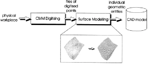
surface patches and applying the scan data to the manufacturing processM. Yang et. al [7] summarized that in
product design, a CAD model often needs to be constructed from a physical part. This process is called reverse
engineering and is performed through dimensional digitising and CAD modelling Ueng Wen-Der et. al [8]
summarized that the issue of surface reconstruction from three-dimensional measured data has been receiving
extensive attention recently Uneg Wen-Der et. al [9] proposed a surface fitting algorithm for sweep surface
reconstruction from three dimensional measured data Varady Tamǎs et. al [10] summarized that in many areas
of industry, it is desirable to create geometric models of existing objects for which no such model is available.
Designer described the process of reverse engineering of shapes. After identifying the purpose of reverse
engineering and the main application areas, the most important algorithmic steps are outlined and various
327 | P a g e
1.1 Role of Reverse engineering in Product development process [26]
Reverse engineering entails the prediction of what a product should do, followed by modeling, analysis,
dissection, and experimentation of its actual performance. Redesign follows reverse engineering, where a
product is evolved to its next offering in a marketplace.
Fig.1: General Reverse Engineering and Re-Design Methodology
Figure1 shows a general composition of a reverse engineering and redesign methodology. Three distinct phases
embody the methodology: reverse engineering, modeling and analysis, and redesign. This approach allows us to
present the necessary material on how to understand the product.
One of the first tasks is to understand the market for the current product is Customer’s need analysis. This
analysis culminates with an understanding of what the customers like and don't like in the product. Based on this
understanding, a variety of redesign opportunities will be apparent. One can then complete a business case
analysis. A business case will define the potential financial gains and risks of pursuing the redesign
opportunities.
The next step in our reverse engineering and redesign process is to make intelligent estimates as to what the
functional model ought to be, using the modeling. This step is important to clarify our preconceived notions of
how the product ought to function and to adopt a functional view of the design task.
The next step in our reverse engineering development process is to dissect the product and understand how it
operates to satisfy or not satisfy the customers. This reverse engineering activity can also be repeated for many
of the competitive products, with additional literature searches on the marketplace to refine the business case
Understanding the component and system technology of the company and its competitors, a real/actual function
structure for the product can be developed
After reverse engineering the product, new concepts can be explored using one of three redesign strategies. The
existing product topology can be maintained and a parametric redesign explored-changes in thickness or
328 | P a g e
different topologies of the functional model. Finally, the entire concept can be replaced with a different
functional layout or with different core technologies. There are several tools and methods in the subsequent
chapters that can be used to support any of these redesign approaches then finally implement that design.
II. INTRODUCTION OF REVERSE ENGINEERING
It formerly meant making a copy of a product, or the outright stealing of ideas from competitors. In current
usage, however, RE has taken on a more positive character and now simply refers to the process of creating a
descriptive data set from a physical object. RE methods and technologies can still be used for negative purposes
like those mentioned, but today there are numerous important legitimate applications for RE.
Reverse engineering is the opposite of Conventional engineering. It takes an existing product, and creates a
CAD model, for modification or reproduction to the design aspect of the product. It can also be defined as the
process or duplicating an existing component by capturing the components physical dimensions. Reverse
engineering is usually undertaken in order to redesign the system for better maintainability or to produce a copy
of a system without access to the design from which it was originally produced.
The goal of reverse engineering an object is to successfully generate a 3D CAD model of an object that can be
used for future modeling of parts where there exists no CAD model.
2.1 Process in Reverse Engineering
(1) 3D scanning of physical projects, typically generating a point cloud. Most scanners nowadays have
embedded point cloud processing and meshing software to output mesh models.
(2) Data processing such as noisy data removal, registration, sampling, smoothing, topology repair and
hole-filling.
(3) Surface reconstruction from mesh or point cloud by direct surface fitting or surface reconstruction through
329 | P a g e
Fig 2: Reverse Engineering process
There are two parts to any reverse engineering application: Scanning and data manipulation. Scanning, also
called digitizing, is the process of gathering the requisite data from an object. Many different technologies are
used to collect three dimensional data. They range from mechanical and very slow, to radiation-based and
highly-automated. Each technology has its advantages and disadvantages, and their applications and
specifications overlap. What eventually comes out of each of these data collection devices, however, is a
description of the physical object in three-dimensional space called a point cloud.
Point cloud data typically define numerous points on the surface of the object in terms of x, y, and z coordinates.
At each x, y, z coordinate in the data where there is a point, there is a surface coordinate of the original object.
However, some scanners, such as those based on X-rays, can see inside an object. In that case, the point cloud
also defines interior locations of the object, and may also describe its density. There is usually far too much
data in the point cloud collected from the scanner or digitizer, and some of it may be unwanted noise. Without
further processing, the data isn’t in a form that can be used by downstream applications such as CAD/CAM
software or in rapid prototyping. Reverse engineering software is used to edit the point cloud data, establish the
interconnectedness of the points in the cloud, and translate it into useful formats such as surface models or STL
files. It also allows several different scans of an object to be melded together so that the data describing the
object can be defined completely from all sides and directions.
Usually, the shortest part of any RE task is scanning or data collection. While there are exceptions, scanning
might only require a few seconds or a few minutes.
330 | P a g e
A. Contact Method: Contacting digitizers, or touch-probes, are often very accurate over a wide measurement
volume, and some instruments in this class are among the most affordable devices available. The two most
commonly known forms are Coordinate Measuring Machines (CMM’s) and mechanical or robotic arms with a
touch probe sensing device.
Fig.3 Coordinate Measuring Machines (CMM)
B. Non-Contact method: 3D scanners record three-dimensional coordinates of numerous points on an object
surface in a relatively short period of time. To accomplish this, a laser beam is projected onto the object surface.
The scanning effect is achieved using one to two mirrors which allow changes of the deflection angle in small
increments. In addition, the entire instrument and/or the object may be rotated to achieve complete
3-dimensional point coverage. High-accuracy recording of angular settlings is important, since the angles together
with the distance measurements determine the reflecting point position.
Two different principles for distance measurement are in use: Ranging lasers using the ―time-of-flight‖ principle
and instruments using CCD cameras where distance measurement is based on the principle of ―triangulation‖.
2.3 Preprocessing
Preprocessing is a process in which Data reduction, Noise filtering, Hole filling is done.
Data Merging [3]: It is procedure of removing overlapping data for multiple sets of scan data and merging
them into one unit i.e. integrating different sets of scan data into one set.
Hole Filling: Suppose at certain location data points are not captured due to some problem at that location
relative data points are assumed.
2.4 Data integration
(a) Registration [3]: It is a procedure of unifying Coordinate systems for multiple sets of scan data. When
acquiring the surface data of the sample part, it is not easy to get the full data on one scan due to the
configuration or topology of the part. The process usually requires multiple scans for an assembly model. Some
identical points have different coordinate data because of the moving of the part. As a result, before the model
reconstruction the digitized data must be registered or aligned. According to the geometric graphics transform
331 | P a g e
The method utilizes measured three datum points data in different coordinate systems to calculate the rotation
and translation matrix. If the measurement error cannot be ignored, the least-square method may be applied to
find the closest points.
(b) Segmentation [6]: It is procedure of tracing the boundary curve of a point and dividing the scan data into
segments. The scan data obtained by non-contact measuring devices consist of a number of points that only
include three-dimensional coordinates on the surface of an object. It is, therefore, difficult to obtain the
geometric information of a part directly from the raw data. In order to extract geometric information, such as
normal’s and curvatures, from the scan data, additional operations such as surface fitting, curve fitting or
polygonizing are required. Once the geometric information of a part is obtained, it can be used for data
reduction, segmentation and other applications.
To facilitate the acquisition of geometric information from the point data, a normal estimation method that is
applicable to the point data acquired by a stripe-type laser scanner was developed. It must be performed after
removing noisy points or outliers from the raw data. The proposed segmentation uses an octree-based 3D-grid
splitting process that uses the iterative subdivisioning of cells based on the normal values of points, and the
region-growing process to merge the divided cells into several groups. In the grid-splitting process, the
evaluation of homogeneity is performed with point data in each cell. Therefore, the evaluation is less sensitive to
noise than the other methods, where the amount of data is very small at the start of the segmentation process. As
well, it can handle a huge amount of unordered point data.
(c) Surface fitting [7]: surface fit is used to fit each set of scan data to obtain a surface patch then blended to
obtain uniform surface model.
III. CURVE REPRESENTATION
A curve can be described by array of coordinate data or by an analytic equation.
The coordinate array method is impractical because the storage required can be excessively large and the
computation to transform the data from one form to another is cumbersome. From design point of view it
becomes difficult to redesign shape of existing object via this method.
Analytic equations of curves provide designers with information such as the effect of data points on curve
behavior, control, continuity and curvature.
Curve can be described mathematically non parametric or parametric equation.
3.1 Non parametric
(1) Explicit: Coordinate Y and Z of point on the curve are expressed as two separate function of third
coordinate X (independent variable).
P = [X Y Z]
= [x f(x) g(x)] T
P: Position vector of point p. There is one to one relationship.
332 | P a g e
Implicit: if coordinate x, y and z are related together by two functions.
F(x, y, z) =0 and G(x, y, z) =0
(ii) Parametric: A new parametric is introduce and the coordinates x, y and z are expressed as function of this
parameters. It allows closed and multivalued functions to be easily defined and replace the use of slopes with
that tangent vector. In parametric form each point on the curve is expressed as functions of parameter u. The
parameter acts as local coordinate for points on the curve. The parametric equation for 3-D curve in space:
P(u) = [ x y z]T = [ x(u) y(u) z(u)]T umin ≤ u ≤ umax.
In this there is one to one mapping from the parametric space (euclidian space E’ in u values) to Cartesian space
(E3 in x, y and z values). Parametric curve is bounded by two parametric values umin. and umax.
These curves can be cubic Spline, Bezier curve or B-Spline but mostly B-Spline is used to generate surface
because it has many advantages over all other.
(a) They provide local control of the curve shape as opposed to global control by using special set of blending
functions that provide local influence.
(b) They also provide ability to add control points without increasing the degree of curve.
(c) It has interpolate or approximate a set of given data points. Interpolation is useful in displaying design or
engineering results such as stress or displacement distribution in a part while approximation is good to design
free form curve.
Free form curves and surfaces in CAD are represented by NURBS Curves and Surfaces. NURBS curves and
surfaces are widely used in CAD for the representation of free-form curves and surfaces due to their interesting
properties such as the ability to handle large surface patches, local controllability and the ability to represent
analytical features as well.
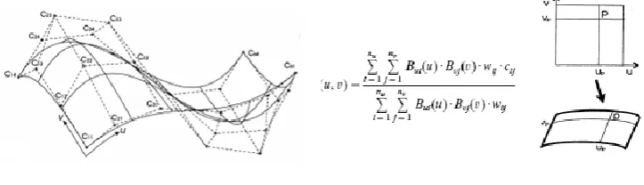
Fig.4.A.b Overview of surface modeling
A NURBS curve is a piecewise rational polynomial and is defined as
333 | P a g e
(d) p a point on the curve and u its location parameter identifying its location within the length of the curve.
(e) n the number of control points. The larger the number of control points, the more details the curve displays,
the smaller the number of control points, however, the smoother the curve will be.
(f) Bi(u) the normalised B-spline functions, uniquely defined by the order k and knot sequence t with k+n
knots. The order is the degree of continuity in a general point on the curve-1. In most CAD applications, cubic
curves, i.e. curves with order_4, are used. The knot sequence contains the parameter values on the curve in
which one polynomial curve segment joins another with (k-2) th continuity.
(g) ci The control points controlling the shape of the curve and wi their respective weights. The weight of a
control point is a measure of the relative importance of this control point to the shape of the curve relative to the
other control points.
A NURBS surface is defined as:
fig. 6 A.d B-Spline Surface
(h) p a point on the surface and u and v its location parameters identifying the location of point p within the
length and width of the surface.
(i) nu And nv the number of control points in the u and v direction.
(j) Bui(u) and Bvi(v) the normalised B-spline functions in the u and v direction. Bui(u) is uniquely defined by the
order kuand knot sequence tuwith ku+nu uknots. Similarly, Bvi(v) is uniquely defined by the order kvand knot
sequence tv with kv+nv v-knots.
(k) cijThe control points controlling the shape of the surface and wijtheir respective weights.
3.2 Advantages of Reverse Engineering
Number of misconception concern the reverse engineering is that its use for the stealing the code. Reverse
engineering is not used only to check the way how it’s working but also check those which do not work so
following are the Different uses of reverse engineering which includes.
The main advantages of Reveres Engineering are.
1) To understand how a product work more widely than by simple observing.
2) Existing program examine, checking errors and their limitation.
3) System and product should be compatible so they can share the data.
4) To understand the limitation of its own product.
5) To check that product so that other one copy of own technology.
334 | P a g e
7) Change old product to new one by adapts them with new system and different platform.
3.3 Application using Reverse engineering
1. There are possible method of reverse engineering which creates the 3DModel of an existing physical part for use in 3D, CAM, CAE, and other software’s. The process of reverse engineering involves measuring the
object model and convert in to the 3 D model.
2. It is also used by business to bring real physical geometry into digital product development environment
and to make the digital 3D record and to compete that product with other competitors. It used to analyzed
and measure like how the product work and what is components.
3. Creating 3D data from an individual, model or sculpture for creating. Scaling or reproducing artwork.
4. Creating 3D data from a model or sculpture for animation in games and movies.
5. Creating data to refurbish or manufacture a part for which there is no CAD data, or for which the data has
become obsolete or lost.
6. Inspection and/or Quality Control - Comparing a fabricated part to its CAD description or to a standard
item.
7. Documentation and/or measurement of cultural objects or artifacts in archaeology, paleontology and other
scientific fields.
8. Fitting clothing or footwear to individuals and determining the anthropometry of a population.
9. Generating data to create dental or surgical prosthetics, tissue-engineered body parts, or for surgical
planning.
10. Documentation and reproduction of crime scenes.
IV. CONCLUSION
Present era is the situation of competitive market ,under the situation of introductory phase and new product
design and part design concept, reverse engineering method is to enhance and easier to get innovative products.
This paper shows some possibilities of use and benefit from utilizing the remethodologies and techniques in
design process. This paper is also given some brief information about characteristics (advantages and
weaknesses) of different scanning systems (contact, or non-contact). For some product development processes
reverse engineering allows to generate surface models by three-dimensional scanning technique, and
consequently this approach must be permits to redesign and manufacture different parts (for cars, for household
appliances) and tools (moulds, dies, press tools) in a short development period. As a result application of reverse
engineering will gain speed for product realization system and largely decreases the design cost.
REFERENCES
1. Hsiao Shih-Wen and Chuang Jiun-Chau, ―A reverse engineering based approach for product form design‖
Elsevier.
2. Yea Xiuzi, Liu Hongzheng, Chen Lei, Chen Zhiyang, Pan Xiang, Zhang Sanyuan, ―Reverse innovative
335 | P a g e
3. Lai J.-Y., Ueng W.-D. and Yao C.-Y., ―Registration and Data Merging for Multiple Sets of Scan Data‖, Int J
Adv Manuf Technol (1999) 15:54–63.
4. Lee H. K., Woo H. and Suk T., ―Data Reduction Methods for Reverse Engineering‖, International Journal
Adv Manuf Technol (2001) 17:735–743.
5. Jamshidi Jafar, Owen Wyn Geraint, Mileham Roy Antony, ―A New Data Fusion Method for Scanned
Models‖.
6. Woo H., Kang E., Wang Semyung, Lee H. Kwan, ―A new segmentation method for point cloud data‖,
International Journal of Machine Tools & Manufacture 42 (2002) 167–178, pergamon.
7. J.-P. Kruth , A. Kerstens, ―Reverse engineering modelling of free-form surfaces from point clouds subject to
boundary conditions‖ , Journal of Materials Processing Technology, Volume 76, Issues 1-3, April 1998,
Pages 120-127.
8. Ueng Wen-Der, Lai Jiing-Yih, ―A sweep-surface fitting algorithm for reverse engineering‖, Computers in
Industry 35_1998.261–273, Elsevier.
9. Uneg Wen-Der, Lai Jiing-Yin and Doong Ji-Liang, ―Sweep-surface reconstruction from three-dimensional
measured data‖, Computer-Aided Design, Vol.30, No. 10, pp.791-805, 1998, Elsevier.
10. Varady Tamǎs, Martin R Ralph and Coxt Jordan, ―Reverse engineering of geometric models-an
Introduction‖, Computer-Aided Design. Vol. 29, No 4, pp. 255-268, 1997, Elsevier.
11. Broberg Ole, ―Integrating ergonomics into the product development process‖, International Journal of
Industrial Ergonomics 19 (1997) 317-327, Elsevier.
12. Nagamachi Mitsuo, ―Kansei engineering as a powerful consumer-oriented technology for product
development‖, Applied Ergonomics 33 (2002) 289–294, Elsevier.
13. Varady Tamǎs, Martin R Ralph and Coxt Jordan, ―Reverse engineering of geometric models-an
Introduction‖, Computer-Aided Design. Vol. 29, No 4, pp. 255-268, 1997, Elsevier.
14. Park H., Kim K., Lee S-C., ―A method for approximate NURBS curve compatibility based on multiple curve
refitting‖, Computer-Aided Design 32 (2000) 237–252, Elsevier.
15. Ma Weiyin, He†‡ Peiren, ―B-spline surface local updating with unorganized points‖, Computer-Aided
Design, Vol. 30, No. 11, pp. 853–862, 1998, Elsevier.
16. Yang M. and Lee E., ―Segmentation of measured point data using a parametric quadric surface
approximation‖, Computer-Aided Design 31 (1999) 449–457, Elsevier.
17. Lshida Junji, ―The general B-spline interpolation method and its application to the modification of curves
and surfaces‖, Computer-Aided Design, Vol. 29, No. 11, pp. 779-790. 1997, Elsevier.
18. Karbacher S., Laboureux X., Schön N., and Häusler G., ―Processing Range Data for Reverse Engineering
and Virtual Reality‖ proceedings of third international conference on 3-D digital imaging 2001,
314-321(2001),IEEE, Quebec, Canada.
19. Tao Jin, Jiyong Kuang, ―A 3-D point sets registration method in reverse engineering‖, Computers &
Industrial Engineering 53 (2007) 270–276, Elsevier.
20. Sagot Jean-Claude, Gouin Vale´rie and Gomes Samuel, ―Ergonomics in product design: safety factor‖,
Safety Science 41 (2003) 137–154,Pergamon.
21. Qin Feng Sheng, Prieto A. Pablo, Wright K. David, ―A novel form design and CAD modelling approach‖,