AN ECONOMIC SOLUTION FOR INDOOR
NAVIGATION SYSTEM USING RFID BASED
POSITIONING ROBOT
Perupogu Vijay Kumar
1, Sk. Lal John Basha
2, L. Srinivas Reddy
31
M.Tech Scholar (ES),
Nalanda Institute of Engg & Tech.
(NIET),
SiddharthaNagar, Guntur, A.P, (India)
2
Assistant
Professor (ECE),
Nalanda Institute of Engg & Tech.
(NIET),
Siddhartha Nagar, Guntur, A.P, India
3
Assistant
Professor (DECS), Nalanda Institute of Engg & Tech. (NIET),
Siddhartha Nagar, Guntur, A.P, (India)
ABSTRACT
The development of a navigation system is an active and interesting research area. In this aspect, the artificial
intelligence in the form of mobile robots comes into existence. Here the implemented robotic system is intended
to develop an indoor navigation system in a cost effective manner and that should be useful in indoor
environments for navigation. While in a search of an inexpensive technology for solving the problem with
indoor navigation, we observed that the RFID will be an effective solution forThe indoor navigation system
involves only in a particular home envoronment, then the RFID tags should be placed in a random positions
according to the requirement. The RFID technology is a very efficient technology for near distance
communication. The proposed system consists of a robotic vehicle designed with 4 wheels and an RFID reader
will be connected to the robot, all the robot functionality and data processing from RFID reader will be
accomplished by a microcontroller. The passive RFID tags will be arranged in certain random positions in a
home where we need to use the indoor navigation robot. The robot will move and navigates according to the
source and destination given by the user in a home.
Keywords
—
Indoor Navigation, RFID, Robotic System
I. INTRODUCTION
The navigation systems are useful in this fast days, where people have to travel all over the world every day and
they can’t remember all the new places before they travel there. So the navigation systems are very important
for everyone. As well the indoor navigation systems also useful incase of elder people and physically challenged
people in homes and also used in the industrial applications for carrying some tools and small objects from one
place to another place in industry work environment. The outdoor navigation system involves any of the
location identification techniques, but the commercial location identification techniques having some GPS
receivers and such kind of electronic gadgets. The problem with the existed systems is they are very expensive
to use in an embedded robotic system, especially for indoor applications of navigation, the GPS receivers may
The indoor navigation system involves the navigation in a single environment or in a home. The GPS receivers
will not give the accurate values of the location details within a home or a premises.Here we need to find an
alternative solution in the form of a less expensive technology for indoor navigation.The RFID technology is
optimized solution for near field communication with a simple RFID tag which contains an unique ID. The
proposed system is equiped with an RFID reader connected to the robot which will read the passive RFID tags
arranged in random positions in a home and move according to the given destination RFID tag.
The RFID technology uses electromagnetic fields to transfer the data, and to identify the unique number in a
RFID tag attached to it. RFID is widely used technology in house hold security systems for lock access and in
organizations also for authentication of their employees in the entry and exit time. Compare to all other
technologies in the field of near field communication, RFID is the very low cost solution and speedy accessing
due to electromagnetic radiation.
The robotic vehicle is additionally equiped with an ultrasonic sensor for detecting any obstacles presence in the
robot moving path. The source and destination input of the robot movement will be given by the user from a
keypad connected to it. Based on the no.of RFID tags arranged in the environment, the keypad gets the input as
a unique number to each RFID node. The purose of indoor navigation will be fulfilled by providing the safety
measures in case of using this robot as a wheel chair for elder people or physically challenging people.
The safety measures for implementing the indoor navigation system in a wheel chair like applications involves
providing the automatic recognition of any obstacles and to stop the vehciles for preventing the accidents. If we
consider the wheel chair is using in a home’s upstair portion, there may be a chance of fall at steps and obstacles
occurred. To solve the problem of safety, we are adding an ultrasonic sensor to the robotic vehicle. The
ultrasonic sensor will detect the obstacle in an enough far distance.
II. LITERATURE REVIEW
The literature review about the proposed system involves three steps of survey of the required technology. First
and foremost, the research done on the RFID technology. The book RFID Applied, John Wiley, 2007, ISBN-10
0471793655; ISBN-13 978-041793656 describes the working principle of RFID and different types of RFID
tags. As mentioned in that book, there are two types of RFID tags classified depends upon the power source
required. The next step in the rsearch was done on robotic technology, as a part in that, the review of book
Mobile Robot Navigation by Alejandra described about the behaviours, structures and devices involved in mobile robots. The book also demonstrates about the path definition of robot moving, localization and obstacle
avoidance.
The review continued on the existed technologies for indoor navigation system.Oneod the existed systems, D. Haas, D. Nielsen, S. Mothersell, K. Yelamarthi, “A Semi-Autonomous Navigational System for the Blind,” ASEE North Central SectionConference, Mar 2010.In this paper, they implemented a navigation
system using GPS and RFID intended to be useful for visually impaired persons. The entire system is integrated
in a guide cane. The existed system was a good navigation system for blind people but also expensive because
of GPS and RFID both integrated in it.
As mentioned above, the most of the existed systems for navigation contains the Global Positioning System
(GPS) and intended to use in outdoor environments. After the research about all this existed technologies and by
observing the differences between various technologies, we proposed the present system for indoor navigation
III. SYSTEM ARCHITECTURE
The above figure shows the block diagram of the proposed robotic system with the primary
elements of the robotic system.
The primary modules in the robotic system involvesRFID reader, Ultrasonic sensor, keypad,
LCD, DC motors and a motor driving IC. A brief description about the hardware modules is
given below.
3.1 PIC16F877A
In our proposed system, PIC16F877A microcontroller is used. The PIC16F877A is an 8-bit
microcontroller. It operates with a +5v supply. Some of the main features of the PIC16F877A
are mentioned below
40 Pin DIP
33 I/O pins
8Kx14 word ROM
368x8 bytes RAM
256x8 bytes EEPROM
Onchip UART
SSP module with I2C and SPI
Two Compare, Capture and PWM modules
All the operations like robot moving control, sensor output monitoring are taken care by the
PIC16F877A microcontroller.
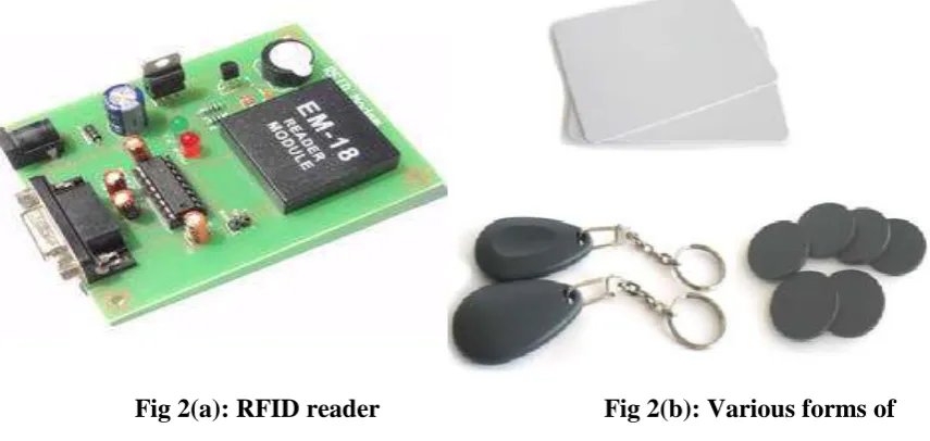
3.2 RFID Readerand RFID Tags
The Radio Frequency Identification (RFID) reader is the device used for reading the unique
ID information stored in the RFID tags. The consists of an electromagnetic coil and an RF
another one is active type. The difference between the active and passive tags comes in the
case of power supply they use. The RFID tags also consists of a electromagnetic coil bound
in it. For the RFID reader, to read the data from the tag, obviously we need external power
source to excite the coil and radiate the RF frequency siganls from it. The active type of
RFID tags require the external power source to it for exciting the coil in the tag, where as the
passive RFID tags do not require any external power source. By considering the differences
between two types of tags, we decided to prefer the passive RFID tags as they don’t need
power source and also low cost.
Fig 2(a): RFID reader
Fig 2(b): Various forms of
RFID tags
The RFID tags will have a unique ID number stored in it. Whenever the RFID tag is placed
near the RFID reader, the frequency will be locked and the data will be read from the RFID
tag.
3.3 Ultrasonic Sensor
The ultrasonic sensor is a sensing device based on electromagnetic echo waves. The sensor
will consists of two parts, one is trigger for electromagnetic signals, that generates the
electromagnetic signals continuously and the second one is echo waves extractor, that
absorbs the echo waves generated after an obstacle is detected to the electromagentocsiganls
radiated.
The ultrasonic sensor calculates the time taken by the echo signal to reach back to the sensor
receiver unit, and detects the distance between the obstacle and the sensor.
3.4 4x3 Keypad
The 4x3 keypad is an input device, that is having 4 rows and 3 coloumns. To reduce the
wastage of the data lines connections to the microcontroller, we use the matrix keypad, in
which we can get the 12 input characters with only 7 input lines. The data absorption from
the keypad involves a scanning method of rows and coloumns.
Fig 4: 4x3 Keypad
3.5 DC Motor
The DC motor is a device that consists of a rotor and a shaft in it. Whenever the power source
is applied to the motor, the rotating part rotor will be rotated according to the polarities of the
applied voltage. The two different polarities of the voltage will rotate the DC motor in either
the direction but the same polarities will stop the motor.
Fig 5: DC Motor
In most of the robotic systems, the DC motor will be used for the wheels rotation. In our
project. We can program the microcontroller according to the direction of the robot by
applying corresponding polarities of the output voltage.
3.6 L293d
Compared to all other IO devices connected to the microcontroller, the DC motor required a
high current rating. The current from the microcontroller output pin will not be sufficient to
rotate a DC motor, so here we are using an IC L293D which amplifies the output current
3.7 16x2 LCD
The 16x2 matrix LCD is used for the displaying of the certain operational conditions of the
robotic system. The moving direction of the robot and the obstacle detection condition will be
displayed on the LCD.
IV. SOFTWARE DESIGN
The proposed system requires the following softwares.
MP Lab
Hi-Tech C Compiler
PIC Tool kit2
The MP lab is an IDE for PIC 14/16/18/32 family microcontrollers. MP lab inbuilt it has
aeditor, compiler, debugger and Hex file generator. It supports almost all microcontrollers
under PIC family.
The Hi-Tech C Compiler is a compiler that should be integrated in MP lab for writing and
compiling the C programs for microcontrollers.
PIC tool kit 2 is a programing software for PIC programming device. The configuration bits
have to set according to the crystal oscillator used and some other parameters used in our
microcontroller before writing the Hex file into microcontroller.
V. WORKING DESCRIPTION
In this implemented robotic vehicle consists og a RFID reader, ultrasonic sensor and a
keypad on it. Initially the robot waits for getting the source and destination input from the
keypad. The RFID tags will be arranged in random positions according to the house
infrastructure.Each card will be assigned with a unique number. Then we have to enter the
source and destination position numbers through keypad. The microcontroller will process
the RFID tag details according to the entered source and destination. Then the robot will
starts moving from the starting position to the source, once it is reached the source, the
microcontroller will analyzes the distance from source to destination and the direction also.
According to the analyzed data, the robot continues it’s movement towards the destination.
For example, let us consider our navigation system contains 4 RFID nodes arranged in
various positions.The nodes have the numbers like 1, 2, 3 and 4. If we entered the source as 1
and destination as 4, the robot starts moving towards node 1, when it is reached 1, then it
redirects to the destination RFID tag and robot moves in the corresponding direction until it
While robot is in moving, if any obstcales found by the ultrasonic sensor, the robot will
immediately stop and move by changing it’s direction.
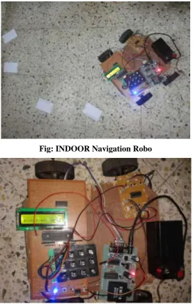
VI. RESULTS
We have placed on the robo on the floor and scattered the RFID cards. The below f igure
gives information about the robo moving on its to reach the destination.
Fig: INDOOR Navigation Robo
Fig ROBO Waiting For The Destination.
VII. CONCLUSION
The proposed robotic system will be an effective solution for solving the problem of indoor
navigation. It is very useful for physically challenged persons as well elder people in home to
accomplish their daily activities independantly. With the use of RFID in the robotic
navigation system, it becomes less expensive compared to other navigation technologies
REFERENCES
[1] K. Yelamarthi, "RFID-Based Interdisciplinary Educational Platform to Improve the Engineering and
Technology Curriculums," Journal of STEM Education: Innovations and Research, vol. 13, no. 5, pp.
46-51, Dec 2012.
[2] D. Haas, D. Nielsen, S. Mothersell, K. Yelamarthi, "A Semi-Autonomous Navigational System for the
Blind," ASEE North Central Section Conference, Mar 2010.
[3] K. Dancer, W. Martin, K. Rock, C. Zeleny, K. Yelamarthi, "The Smart Cane: An Electrical Engineering
Design Project," ASEE North Central Section Conference, Apr 2009.
[4] S. K. Boddhu, J. C. Gallagher, "Evolving Neuromorphic Flight Control for a Flapping-Wing Mechanical
Insect," International Journal of Intelligent Computing and Cybernetics, vol. 3 iss: 1, pp. 94-116, 2010.
[5] S. K. Boddhu, J. C. Gallagher, J. C. "Evolved Neuromorphic Flight Control for a Flapping-Wing
Mechanical Insect". IEEE Congress on Evolutionary Computation, pp. 1744-1751, June 2008.
[6] L. Chunag, "Object localization strategy for a mobile robot using RFID," Master's Thesis, Department of
Computing Science, Umea University, Umea, Sweden, July 2012.
[7] Z. Zhang, "I am the Antenna: Accurate Outdoor AP Location using Smart phones," Proceedings of ACM
MobiCom, Sep 2011.
[8] J. S. Choi, "Accurate and cost efficient object localization using passive UHF RFID," PhD thesis work,
2011.
[9] S. Schneegans, P. Vorst, A. Zell, "Using RFID Snapshots for Mobile Robot Self-Localization," Proceeding
of European Conference on Mobile Robots, pp. 241-246, 2007.
[10] S. Park, S. Hashimoto, "Autonomous Mobile Robot Navigation Using Passive RFID in Indoor
Environment," IEEE Transaction on Industrial Electronics, vol. 56, no. 7, pp. 2366-2373, July 2009.
[11] M. Kim, N. Chong, "Direction Sensing RFID Reader for Mobile Robot Navigation," IEEE Transactions on
Automation Science and Engineering, vol. 6, no. 1, pp. 44-54, Jan 2009.
[12] iRobot Create Programmable Robot, [Online] Available: http://store. irobot. com/shop/index.
jsp?categoryId=3311368.
PERUPOGU VIJAY KUMAR, pursuing M.Tech (ES) from Nalanda Institute of
Engineering & Technology (NIET), Siddhartha Nagar, Kantepudi (v), Sattenapalli,
Guntur, Andhra Pradesh, India - 522483
SK.LAL JOHN BASHA,working as Assistant Professor (ECE) in Nalanda Institute
of Engineering & Technology (NIET), Siddhartha Nagar, Kantepudi (v),
Sattenapalli, Guntur, Andhra Pradesh, India – 522483,
L. SRINIVAS REDDY, working as Assistant Professor (DECS) from Nalanda Institute of Engineering & Technology(NIET), Siddhartha Nagar, Kantepudi (v),