technologies
Article
Open Source Waste Plastic Granulator
Arvind Ravindran1, Sean Scsavnicki1, Walker Nelson1, Peter Gorecki1, Jacob Franz1, Shane Oberloier2, Theresa K. Meyer3, Andrew R. Barnard1and Joshua M. Pearce2,3,4,*
1 Department of Mechanical Engineering–Engineering Mechanics, Michigan Technological University,
Houghton, MI 49931, USA; [email protected] (A.R.); [email protected] (S.S.); [email protected] (W.N.); [email protected] (P.G.); [email protected] (J.F.); [email protected] (A.R.B.)
2 Department of Electrical & Computer Engineering, Michigan Technological University, Houghton,
MI 49931, USA; [email protected]
3 Department of Material Science & Engineering, Michigan Technological University, Houghton,
MI 49931, USA; [email protected]
4 Department of Electronics and Nanoengineering, School of Electrical Engineering, Aalto University,
FI-00076 Espoo, Finland
* Correspondence: [email protected]; Tel.:+1-906-487-1466
Received: 30 August 2019; Accepted: 9 October 2019; Published: 14 October 2019
Abstract: In order to accelerate deployment of distributed recycling by providing low-cost feed stocks of granulated post-consumer waste plastic, this study analyzes an open source waste plastic granulator system. It is designed, built, and tested for its ability to convert post-consumer waste,
3D printed products and waste into polymer feedstock for recyclebots of fused particle/granule
printers. The technical specifications of the device are quantified in terms of power consumption (380 to 404 W for PET and PLA, respectively) and particle size distribution. The open source device can be fabricated for less than $2000 USD in materials. The experimentally measured power use is only a minor contribution to the overall embodied energy of distributed recycling of waste plastic. The resultant plastic particle size distributions were found to be appropriate for use in both recyclebots and direct material extrusion 3D printers. Simple retrofits are shown to reduce sound levels during operation by 4dB-5dB for the vacuum. These results indicate that the open source waste plastic granulator is an appropriate technology for community, library, maker space, fab lab, or small business–based distributed recycling.
Keywords: 3D printing; additive manufacturing; distributed manufacturing; distributed recycling; granulator; shredder; open hardware; fab lab; open-source; polymers; recycling; waste plastic; extruder; upcycle; circular economy
1. Introduction
The open-source release of the self-replicating rapid prototyper (RepRap) 3D printer [1–3] greatly
expanded access to additive manufacturing (AM) because of several orders of magnitude reduction
in costs [4]. As open-source RepRap 3D printers spawned hundreds of clones, fused filament
fabrication (FFF) enabled a shift in the trend from centralized to consumer (or prosumer) distributed
manufacturing [4–8]. Consumers now use RepRaps or pre-built desktop 3D printers to manufacture
all manner of products from toys to household items less expensively than purchasing them from
conventional brick and mortar or online retailers [9–11]. The peer-reviewed business literature now
recognizes this potential shift in manufacturing [12–14], which is brought on not only by the open
source sharing of 3D printer designs, but now more importantly because of millions of freely shared
digital designs of other products that are 3D printable [9]. Any level of consumer from scientific
research funders to arthritis patients [15] can earn a high return on investment (ROI) [16] for distributed
manufacturing with commercial polymer 3D printing filament based on downloaded substitution
values [17]. However, commercial 3D printing filament is still sold for roughly an order of magnitude
more than the cost of the raw materials of virgin plastic pellets (e.g., $15–100 USD/kg vs $1–10 USD/kg).
This has reduced adoption of AM at the prosumer level [18]. There are two methods to overcome this
artificial cost barrier for wider spread distributed manufacturing: (1) use distributed recycling to make filament and (2) skip the entire process of fusing filament into a 3D printed object by printing directly from polymer granules, shards or particles.
Three-dimensional printing filament can be manufactured economically using distributed means
with an open source waste plastic extruder (often called a recyclebot) [19]). Recycling is well-known
to be environmentally beneficial, and performing distributed recycling of plastic waste into filament decreases the embodied energy of filament by 90% compared to traditional centralized filament
manufacturing using fossil fuels as inputs [20–22]. Using distributed recycling fits into the circular
economy paradigm [23–26] as it eliminates most embodied energy and pollution from transportation
between processing steps. Many open-source commercial and non-commercial recyclebots have been
developed [27], including a 3D printable version [28]. Many research groups and companies have
demonstrated that pre-consumer and post-consumer waste polymers can be recycled into 3D printing filaments, including
• polylactic acid (PLA) [28–32];
• acrylonitrile butadiene styrene (ABS) [24,33–36];
• high-density polyethylene (HDPE) [19,37,38];
• polypropylene (PP) [38];
• polystyrene (PS) [38];
• polyethylene terephthalate (PET) [39];
• linear low-density polyethylene (LLDPE) and low-density polyethylene (LDPE) [40];
• elastomers [8].
In addition, filaments can be made from polymer composites using carbon-reinforced plastic [41]
and various types of waste wood [42,43]. Unfortunately, each melt-solidification degrades the
mechanical properties of the resultant 3D print [44,45], so recycling is limited to about five
cycles [29,30,46] or using chemical recycling [47] without use some means of reinforcement or blending
with virgin materials. The potential for such distributed recycling could be either completely distributed (where the consumer recycles their own plastic in their home or business) or part of a local closed-loop
supply chain [48].
The second method, however, eliminates the need for filament entirely, as 3D printers have been developed that can print directly from particles, pellets, flakes, regrind, or shreds of recycled plastic. These fused particle fabrication (FPF) or fused granular fabrication (FGF) 3D printers are becoming
established in the academic [49–54], maker [55–57], and commercial venues (e.g., GigabotX, PartDaddy,
Cheetah Pro, David, Erecto-Struder, etc.). FPF/FGF printing is possible with recycled materials [58–60],
as is using FGF printing of molds for distributed injection molding of larger replicate products [60].
Both the widespread deployment of distributed recycling with recyclebots and FPF/FGF are being
restricted because of the lack of accessibility of low-cost pelletizers and choppers to turn post-consumer plastic products into polymer feedstock. In general, these are large industrial machines not conducive for makerspaces, fab labs, research, or consumer use because of their high throughputs, noise, and capital costs. This study attempts to a provide a new low-cost but medium-scale technology for transforming plastic recyclables into usable 3D printing feedstock in the form of granules (or particles). In order to provide a low-cost tool for making polymer feedstock from post-consumer waste this
study follows the open-source hardware design paradigm [61,62], which has proven so successful for
3D printing in general. A novel open source waste plastic granulator system is designed, built, and tested for its ability to convert post-consumer waste, 3D printed products, and 3D printer waste into
Technologies2019,7, 74 3 of 21
are quantified in terms of power consumption and particle size of the output. In order for the device to operate in a fab lab (or similar environment), a noise reduction system is designed, added, and analyzed. The results are presented and discussed.
2. Design Concept
The design of the open source waste plastic granulator system is divided into four separate sub-systems, each responsible for parts of the machine that serve a specific function.
1. Power Transmission: This system encompasses all machine parts needed to convert the electrical
energy being input to the system into mechanical energy, as well as transmit that mechanical
energy to the plastic cutting/granulation system.
2. Plastic Cutting/Granulation: This system is the one that directly interacts with the plastic in order
to cut it into small chunks. It is responsible for cutting plastic as well as ejecting granules after they have reached a uniform size.
3. Material Guidance/Structural: This system involves any parts that keep the plastic feedstock
inside of the proper cutting area during operation or guide the feedstock during its journey. It includes the hopper chute, the hopper lip, the granulation chamber lip, any mechanism used to hold the hopper to the granulation chamber, and the upper surfaces of the granulation chamber.
4. Electrical: This system encompasses all of the components required to convert electrical energy
from electrical grid power into rotational energy, as well as any other electrical peripherals present on the machine. This includes the electrical box, safety switches, circuit board, motor, and a microcontroller.
Together, these systems operate with the end goal of transforming plastic recyclables into usable 3D printing feedstock in the form of granules (or particles). The main concepts and parts in each sub-system will be described, but the full open hardware details including the bill of materials (BOM), drawings for custom parts, CAD files, build instructions, and design reports of previous versions are
housed at the Open Science Framework [63].
2.1. Power Transmission System
The power transmission system transfers rotational mechanical energy from the motor spindle to the cutting rotor shaft. As a first step towards designing this subsystem of the machine the design team made the decision that a one-phase AC motor (IronHorse, Automation Direct, Cumming, GA,
USA; 1–1/2hp 115/230 VAC motor, with 15.9mm shaft diameter wired for 230 V) would be used to
supply mechanical power to the machine. This method of mechanical power delivery is the most reliable and easiest way for an individual to drive a machine from their home circuitry. Pulleys and belts are used to convey power to the cutting rotor; belts are not only inexpensive when compared to a gearbox but are also more user friendly since they are easy to install, maintain, and adjust once assembled. An isolated view of the 3D model for the power transmission subsystem and all of its
components can be seen in Figure1.
As seen in the Figure1, the parts of the power transmission system are as follows: AC Motor,
pulleys, belts, flange-mount bearings, rotor shaft, quick-disconnect (QD) bushings, and weld-on hubs (plus mounting hardware). The motor selected to drive the granulator is a 1.5 HP motor with a spindle speed of ~1800 RPM. On a previous version of the open source waste plastic granulator, the optimal
rotor speed for cutting was found to be around 750 RPM [62]; this speed was also used for this design
Technologies2019,7, 74 4 of 21
clamp to the shaft. These components were then bolted to the cutting rotor so that the blades would
spin with the shaft (see Figure2).
2. Design Concept
The design of the open source waste plastic granulator system is divided into four separate sub-systems, each responsible for parts of the machine that serve a specific function.
1. Power Transmission: This system encompasses all machine parts needed to convert the electrical energy being input to the system into mechanical energy, as well as transmit that mechanical energy to the plastic cutting/granulation system.
2. Plastic Cutting/Granulation: This system is the one that directly interacts with the plastic in order to cut it into small chunks. It is responsible for cutting plastic as well as ejecting granules after they have reached a uniform size.
3. Material Guidance/Structural: This system involves any parts that keep the plastic feedstock inside of the proper cutting area during operation or guide the feedstock during its journey. It includes the hopper chute, the hopper lip, the granulation chamber lip, any mechanism used to hold the hopper to the granulation chamber, and the upper surfaces of the granulation chamber.
4. Electrical: This system encompasses all of the components required to convert electrical energy from electrical grid power into rotational energy, as well as any other electrical peripherals present on the machine. This includes the electrical box, safety switches, circuit board, motor, and a microcontroller.
Together, these systems operate with the end goal of transforming plastic recyclables into usable 3D printing feedstock in the form of granules (or particles). The main concepts and parts in each sub-system will be described, but the full open hardware details including the bill of materials (BOM), drawings for custom parts, CAD files, build instructions, and design reports of previous versions are housed at the Open Science Framework [63].
2.1. Power Transmission System
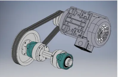
The power transmission system transfers rotational mechanical energy from the motor spindle to the cutting rotor shaft. As a first step towards designing this subsystem of the machine the design team made the decision that a one-phase AC motor (IronHorse, Automation Direct, Cumming, GA, USA; 1– 1/2hp 115/230 VAC motor, with 15.9mm shaft diameter wired for 230 V) would be used to supply mechanical power to the machine. This method of mechanical power delivery is the most reliable and easiest way for an individual to drive a machine from their home circuitry. Pulleys and belts are used to convey power to the cutting rotor; belts are not only inexpensive when compared to a gearbox but are also more user friendly since they are easy to install, maintain, and adjust once assembled. An isolated view of the 3D model for the power transmission subsystem and all of its components can be seen in Figure 1.
Figure 1. Power transmission system design of the open source waste plastic granulator.
As seen in the Figure 1, the parts of the power transmission system are as follows: AC Motor, pulleys, belts, flange-mount bearings, rotor shaft, quick-disconnect (QD) bushings, and weld-on hubs
Figure 1.Power transmission system design of the open source waste plastic granulator.
Technologies 2019, 7, x FOR PEER REVIEW 4 of 21
(plus mounting hardware). The motor selected to drive the granulator is a 1.5 HP motor with a spindle speed of ~1800 RPM. On a previous version of the open source waste plastic granulator, the optimal rotor speed for cutting was found to be around 750 RPM [62]; this speed was also used for this design as well, leading to a set ratio of pulley diameters of about 1:2.4. A 100.33 mm diameter pulley was chosen to connect to the motor spindle using a quick-disconnect style bushing. A 222.25 mm diameter pulley was used to attach to the cutting rotor shaft, also with a quick-disconnect bushing. Both pulleys have two channels for v-belts to ensure there is no slippage during operation. In order to keep the cutting rotor shaft spinning about its major axis, two large flange-mount bearings were used. In order to connect the shaft to the cutting rotor, QD bushings were used in conjunction with weld-on hubs to clamp to the shaft. These components were then bolted to the cutting rotor so that the blades would spin with the shaft (see Figure 2).
2.2. Plastic Cutting System
The plastic cutting subsystem is, out of all of the subsystems, the most directly related to the overall function of the machine as it is responsible for transforming plastic waste/recyclables into granules of a specific size. In order to do this, the design team picked out many different forms that would satisfy the subsystem’s purpose and compared them using a decision matrix (details of which are found in the OSF database [63]). From the decision matrix, the best option was found to be the fly knife design, consisting of two large rotating blades (fly knives) that pass close to a fixed blade during operation (Figure 2). Shear force on the plastic between the blades is the main cutting method.
Figure 2. Plastic cutting system design of the open source waste plastic granulator. There is about 2mm gap between the knives and the screen.
The plastic cutting system consists of four separate components (plus mounting hardware). Two blade arms will connect to the cutting rotor shaft (shown in Figure 2) and will spin with the shaft. Connected to either end of each blade arm in the configuration shown below are two fly knives, which will contact the plastic within the cutting chamber and shear through it. To help with the cutting of the plastic granules, there are two more pieces in this system that both interact with the rotating fly knives, the granulation screen and the bed blade. As the fly knives rotate in the granulation chamber, they will pass very close to the fixed bed blade on the right side of Figure 2.
This is where the large pieces entering the cutting chamber will be sheared for the first time. In the design, all stress-bearing components related to this large cutting force were designed to be able to cut 22.2 mm cubes of nylon mill stock. Once large pieces have been cut for the first time by the bed blade, they will accumulate on the surface of the granulation screen. The clearance between the tip of the fly knives during rotation and the inside of the screen in 3 mm, which means that any larger granules will get pinched between the screen and the blade and be sheared to a smaller size. Once the granules are smaller than 6 mm in all dimensions, they are pulled through the holes located in the granulation screen and into a collection chamber by a vacuum. Thus, the vacuum is used for the collection of the granules of cut plastic. In order to make the blade arms rotate, as described in Section 2.1, weld-on hubs attached to the shaft were bolted onto the blade arms. For the cutting system fly knife blades were manufactured from O1 tool steel and a Bridgeport was used to manually face fill the stock down to dimension. Once Figure 2.Plastic cutting system design of the open source waste plastic granulator. There is about 2mm gap between the knives and the screen.
2.2. Plastic Cutting System
The plastic cutting subsystem is, out of all of the subsystems, the most directly related to the
overall function of the machine as it is responsible for transforming plastic waste/recyclables into
granules of a specific size. In order to do this, the design team picked out many different forms that
would satisfy the subsystem’s purpose and compared them using a decision matrix (details of which
are found in the OSF database [63]). From the decision matrix, the best option was found to be the fly
knife design, consisting of two large rotating blades (fly knives) that pass close to a fixed blade during
operation (Figure2). Shear force on the plastic between the blades is the main cutting method.
The plastic cutting system consists of four separate components (plus mounting hardware).
Two blade arms will connect to the cutting rotor shaft (shown in Figure2) and will spin with the shaft.
Connected to either end of each blade arm in the configuration shown below are two fly knives, which will contact the plastic within the cutting chamber and shear through it. To help with the cutting of the plastic granules, there are two more pieces in this system that both interact with the rotating fly knives, the granulation screen and the bed blade. As the fly knives rotate in the granulation chamber, they will
pass very close to the fixed bed blade on the right side of Figure2.
Technologies2019,7, 74 5 of 21
the collection of the granules of cut plastic. In order to make the blade arms rotate, as described in
Section2.1, weld-on hubs attached to the shaft were bolted onto the blade arms. For the cutting system
fly knife blades were manufactured from O1 tool steel and a Bridgeport was used to manually face fill the stock down to dimension. Once block was dimensioned down an end mill was used to cut slots and pockets needed to attach the bolts. Finally, an angle vise was used to face mill the bevel
for the cutting edge all to the specifications with the drawings [63]. After machining the blades were
heat-treated using an electric furnace and quenched in oil in order to harden the tool steel following standard protocols. For the granulation screen, a seamless pipe cut to width was used as the starting material, but due to manufacturing methods the pipe had internal stresses. Heat treating the pipe in an electric furnace and then letting it air cool relieved the internal stresses. This step is not required if tools are not available as one could continue to cut the pipe, but stress may not be relieved, and it will spring open. After the stress relief heat treatment, an angle grinder is used to cut a straight line down the length of the pipe and then cut the other side of the pipe to provide equal halves, which are then subsequently drilled as shown in the Figures.
2.3. Material Guidance
The material guidance system is responsible for containing the waste plastic both before and after the cutting operation. In addition to guiding materials, this system also serves as the structure upon which all other subsystems are constructed. The feedstock is guided using a sloped tube as shown in
Figure3.
Technologies 2019, 7, x FOR PEER REVIEW 5 of 21
block was dimensioned down an end mill was used to cut slots and pockets needed to attach the bolts. Finally, an angle vise was used to face mill the bevel for the cutting edge all to the specifications with the drawings [63]. After machining the blades were heat-treated using an electric furnace and quenched in oil in order to harden the tool steel following standard protocols. For the granulation screen, a seamless pipe cut to width was used as the starting material, but due to manufacturing methods the pipe had internal stresses. Heat treating the pipe in an electric furnace and then letting it air cool relieved the internal stresses. This step is not required if tools are not available as one could continue to cut the pipe, but stress may not be relieved, and it will spring open. After the stress relief heat treatment, an angle grinder is used to cut a straight line down the length of the pipe and then cut the other side of the pipe to provide equal halves, which are then subsequently drilled as shown in the Figures.
2.3. Material Guidance
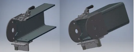
The material guidance system is responsible for containing the waste plastic both before and after the cutting operation. In addition to guiding materials, this system also serves as the structure upon which all other subsystems are constructed. The feedstock is guided using a sloped tube as shown in Figure 3.
Figure 3. Material guidance system (cut section and completed) for the open source waste plastic granulator.
Overall, the main component used for material guidance is a large steel square tube that not only provides a smooth, enclosed surface for the waste plastic to slide on while it is on its way to be cut, but also a very strong and rigid structure that can be built upon. Attached to this large (8” (203 mm) width) square tube are several other components that support the plastic cutting and power transmission systems. The two large rounded plates attached to the vertical faces of the tube are what hold the bearings from the power transmission system in place. The angle iron on the bottom part of the tube serves two purposes. The larger piece holds the fixed bed blade in place during operation, as well as clamping to the second piece of angle iron shown, which secures the granulation screen in place for cutting. The materials on the top of the tube are all responsible for holding the opposite side of the granulation screen in place and allows the user to disconnect the granulation screen quickly from one side. This system also includes a secondary tube acting as a hopper for funnelling material directly from the user’s hand into the machine as well as a server rack cart that is used to house the main cutting mechanism. However, these components are not shown above for clarity.
2.4. Electrical
The electrical system in the machine serves three purposes—powering the motor, powering the granule extraction vacuum, and monitoring the power consumption of the machine. These functions are accomplished simply since both the vacuum and the motor require no more than a simple on/off control scheme. Both the vacuum and the motor are connected directly to 120VAC mains power and use simple switches to control them. In addition, an emergency-stop switch is included in the circuitry to cut power to the whole machine if necessary. The final accessory included in the electronic Figure 3.Material guidance system (cut section and completed) for the open source waste plastic granulator.
Overall, the main component used for material guidance is a large steel square tube that not only provides a smooth, enclosed surface for the waste plastic to slide on while it is on its way to be cut, but also a very strong and rigid structure that can be built upon. Attached to this large (8” (203 mm) width) square tube are several other components that support the plastic cutting and power transmission systems. The two large rounded plates attached to the vertical faces of the tube are what hold the bearings from the power transmission system in place. The angle iron on the bottom part of the tube serves two purposes. The larger piece holds the fixed bed blade in place during operation, as well as clamping to the second piece of angle iron shown, which secures the granulation screen in place for cutting. The materials on the top of the tube are all responsible for holding the opposite side of the granulation screen in place and allows the user to disconnect the granulation screen quickly from one side. This system also includes a secondary tube acting as a hopper for funnelling material directly from the user’s hand into the machine as well as a server rack cart that is used to house the main cutting mechanism. However, these components are not shown above for clarity.
2.4. Electrical
The electrical system in the machine serves three purposes—powering the motor, powering the granule extraction vacuum, and monitoring the power consumption of the machine. These functions
control scheme. Both the vacuum and the motor are connected directly to 120VAC mains power and use simple switches to control them. In addition, an emergency-stop switch is included in the circuitry to cut power to the whole machine if necessary. The final accessory included in the electronic circuit for this machine is a multimeter that provides a digital readout with information on the power consumption of the machine. All of the components in the electrical system were designed to operate
using less than 15 Amps during steady-state conditions so that the machine could be run offof a
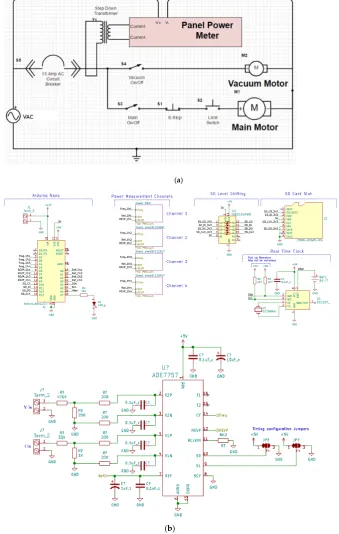
standard in-home wall outlet. A circuit diagram for the electrical system is included in Figure4a.
Technologies 2019, 7, x FOR PEER REVIEW 6 of 21
circuit for this machine is a multimeter that provides a digital readout with information on the power consumption of the machine. All of the components in the electrical system were designed to operate using less than 15 Amps during steady-state conditions so that the machine could be run off of a standard in-home wall outlet. A circuit diagram for the electrical system is included in Figure 4a.
(a)
(b)
Technologies2019,7, 74 7 of 21
2.5. Peripheral Parts Assembly
Together, the four systems described in Sections2.1–2.4work together to achieve the overall
objective of the design of the open source waste plastic granulator. Other than getting the material from place to place, all of the actual manipulation of the plastic to transform it from stock material into feedstock occurs due to the cutting and power transmission systems. An overall view of the machine’s
core systems is shown in Figure5.
Technologies 2019, 7, x FOR PEER REVIEW 7 of 21
Figure 4. (a)Circuit diagram for electrical control system of the open source waste plastic granulator
and (b) circuit diagrams.
2.5. Peripheral Parts Assembly
Together, the four systems described in Section 2.1–2.4 work together to achieve the overall objective of the design of the open source waste plastic granulator. Other than getting the material from place to place, all of the actual manipulation of the plastic to transform it from stock material into feedstock occurs due to the cutting and power transmission systems. An overall view of the machine’s core systems is shown in Figure 5.
Figure 5. Overall design setup of the open source waste plastic granulator with primary parts labeled
with green arrows. Red arrows indicate the path of material flow.
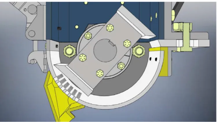
Figure 5 shows the assembly of the three mechanical design systems, including all of the parts explained earlier as well some 3D printed parts and several parts not shown before. The total system dimensions are width of 0.72m, depth of 0.55m and height of 1.47m. The system has a mass of 125 kg. As can be seen in the above picture the server rack cart that was mentioned in the material guidance system is housing the main systems of the granulator. It holds the machine components so that the major axis of the large square tube is angled to allow plastic pieces to slide into the cutting mechanism. To accomplish this, several standard size ½” (12.7 mm)) steel pipes are attached to the server rack using u-bolts. The pipe in the rear (as shown in Figure 5) is attached directly to the bottom of the steel tube using pipe straps, while the pipe in the front is attached via nylon strapping to the eye-bolts shown on the top of the steel tube in the above figure. This is done to allow the builder of the machine to easily add a vibration-dampening spring at the front attachment point to mitigate any rotational imbalance that may be present in the machine. The hopper consists of the large tube sticking out of the top of the server rack as well as a plate that allows it to attach to the back of the square steel tube/main machine body. This allows users to safely place materials into the machine for cutting. The bend that materials will have to pass through in order to get from the machine’s opening to the cutting mechanism ensures that a user cannot accidentally place their hands/arms inside the machine while it is cutting as well as stops granules from flying out of the machine during operation. To highlight the interaction between all three main mechanical systems a cutaway view showing the assembled granulation chamber in Figure 6.
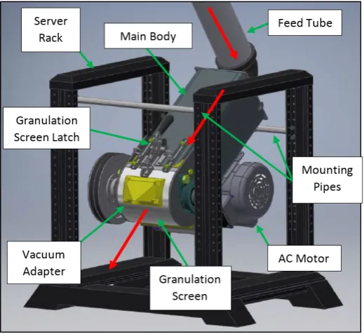
Figure 5.Overall design setup of the open source waste plastic granulator with primary parts labeled with green arrows. Red arrows indicate the path of material flow.
Figure5shows the assembly of the three mechanical design systems, including all of the parts
explained earlier as well some 3D printed parts and several parts not shown before. The total system dimensions are width of 0.72 m, depth of 0.55 m and height of 1.47 m. The system has a mass of 125 kg. As can be seen in the above picture the server rack cart that was mentioned in the material guidance system is housing the main systems of the granulator. It holds the machine components so that the major axis of the large square tube is angled to allow plastic pieces to slide into the cutting mechanism.
To accomplish this, several standard size 12” (12.7 mm)) steel pipes are attached to the server rack using
u-bolts. The pipe in the rear (as shown in Figure5) is attached directly to the bottom of the steel tube
using pipe straps, while the pipe in the front is attached via nylon strapping to the eye-bolts shown on the top of the steel tube in the above figure. This is done to allow the builder of the machine to easily add a vibration-dampening spring at the front attachment point to mitigate any rotational imbalance that may be present in the machine. The hopper consists of the large tube sticking out of the top of the
server rack as well as a plate that allows it to attach to the back of the square steel tube/main machine
body. This allows users to safely place materials into the machine for cutting. The bend that materials will have to pass through in order to get from the machine’s opening to the cutting mechanism ensures
that a user cannot accidentally place their hands/arms inside the machine while it is cutting as well as
stops granules from flying out of the machine during operation. To highlight the interaction between all three main mechanical systems a cutaway view showing the assembled granulation chamber in
Technologies 2019, 7, x FOR PEER REVIEW 8 of 21
Figure 6. Cutaway of mechanical systems in the open source waste plastic granulator.
2.6. Cutting Force Design Analysis
The cutting operation that takes place during the operation of the granulator is unpredictable, so a simulation was run of the cutting forces that occur during the operation of the granulator [63]. These forces are important because they allow for the calculation of the stresses that occur inside the key stress-bearing elements of the design. The method and findings are in the OSF database [63].
The stress levels inside the blade arm as well as the fly knife bolts are well below the acceptable level for steel materials. In order to achieve this, it was determined that the blade arms must be made out of 19 mm × 63.5 mm steel flat stock, and that the bolts must be 16 UNC (9.525 mm) grade 8 hex cap screws. Previous simulations found that a 12.7 mm thick piece of angle iron with side lengths of 76.2 mm would be suitably strong for this piece. In this study, 6.35 mm–20 UNC bolts were selected despite being over engineered because they proved inexpensive for this application. After iterating the simulation to find the optimal size for the bed blade mounting bolts, both locations were
considered, and 912.7 mm −12 UNC grade 8 hex cap bolts were chosen. Standard fatigue analysis [64]
was performed, and it was found that the grade 9 bolts responsible for attaching the fly knife blades to the blade arms are predicted to fail due to fatigue before infinite life. That being said, the analysis done assumes that a 19 mm nylon block will enter the machine once every time one knife rotates, which, for normal operation, is very unlikely. For normal use, the stresses present will never reach the values used for analysis. However, users planning on using this machine for nylon recycling should replace these bolts every month in order to avoid failure due to fatigue. The maximum torque acting on the cutting rotor during operation is slightly less than 1500 N-m. In order to attach the cutting rotor to the shaft two SK type QD bushings were chosen, since each bushing can support a torque of about 800 N-m. Together, these two bushings can support a maximum torque of 1580 N-m, a torque that should never be exceeded during the normal operation of the machine. In conclusion, the design simulation indicated that the technology as designed would be able to cut a maximum thickness of nylon stock of 19 mm, i.e. a cube measuring 19 mm on each side is the largest piece of plastic stock that should be inserted into the machine.
3. Material and Methods
3.1. Technical Specifications: Power Consumption and Particle Size
The power consumption operating the granulator as measured with an open-source printed circuit board and Arduino Nano attached to the power supply to measure the power output of the while it was processing different materials. During each of the power recording sessions,
Figure 6.Cutaway of mechanical systems in the open source waste plastic granulator.
2.6. Cutting Force Design Analysis
The cutting operation that takes place during the operation of the granulator is unpredictable,
so a simulation was run of the cutting forces that occur during the operation of the granulator [63].
These forces are important because they allow for the calculation of the stresses that occur inside the
key stress-bearing elements of the design. The method and findings are in the OSF database [63].
The stress levels inside the blade arm as well as the fly knife bolts are well below the acceptable level for steel materials. In order to achieve this, it was determined that the blade arms must be made
out of 19 mm×63.5 mm steel flat stock, and that the bolts must be 16 UNC (9.525 mm) grade 8 hex
cap screws. Previous simulations found that a 12.7 mm thick piece of angle iron with side lengths of 76.2 mm would be suitably strong for this piece. In this study, 6.35 mm–20 UNC bolts were selected despite being over engineered because they proved inexpensive for this application. After iterating the simulation to find the optimal size for the bed blade mounting bolts, both locations were considered,
and 912.7 mm−12 UNC grade 8 hex cap bolts were chosen. Standard fatigue analysis [64] was
performed, and it was found that the grade 9 bolts responsible for attaching the fly knife blades to the blade arms are predicted to fail due to fatigue before infinite life. That being said, the analysis done assumes that a 19 mm nylon block will enter the machine once every time one knife rotates, which, for normal operation, is very unlikely. For normal use, the stresses present will never reach the values used for analysis. However, users planning on using this machine for nylon recycling should replace these bolts every month in order to avoid failure due to fatigue. The maximum torque acting on the cutting rotor during operation is slightly less than 1500 N-m. In order to attach the cutting rotor to the shaft two SK type QD bushings were chosen, since each bushing can support a torque of about 800 N-m. Together, these two bushings can support a maximum torque of 1580 N-m, a torque that should never be exceeded during the normal operation of the machine. In conclusion, the design simulation indicated that the technology as designed would be able to cut a maximum thickness of nylon stock of 19 mm, i.e., a cube measuring 19 mm on each side is the largest piece of plastic stock that should be inserted into the machine.
3. Material and Methods
3.1. Technical Specifications: Power Consumption and Particle Size
Technologies2019,7, 74 9 of 21
was processing different materials. During each of the power recording sessions, thermoplastic was
inserted at a rate the granulator could handle. This rate is not measured, as it highly depends on the geometry and density of the inserted plastic.
The AC power measurement system is a custom system designed for measuring and recording general AC power consumption data. The device is prototyped as a custom professionally manufactured printed circuit board (PCB). The PCB was then soldered by hand. The system is capable of making four separate AC measurements. Each leg’s measurements are connected to a dedicated Analog Devices ADE7757 energy metering integrated circuit (IC). The IC meets the IEC61036 accuracy requirements for power measurements. The ADE7757 transmits the wattage signal through its CF pin, and is captured
by the on-board Arduino Nano. An overall system schematic is shown in Figure4b.
For analyzing the power consumption of the shredder, both input legs of the 220 VAC power input to the control electronics are monitored. Each leg’s corresponding voltage is measured by direct connection, and current is measured using 100A non-invasive current transformers. The values are operated on by a linear calibration, and then written to a microSD card, with time stamps generated by the on-board real time clock. The size characteristics of the particles for the resultant granulated
material were quantified using digital imaging and the open source Fiji/ImageJ using techniques
discussed previously [60]. ImageJ works by analyzing a photograph of the particles and raising
the contract of the photograph until all particles are clearly recognizable to the program as solid black pieces. From the analysis, a spreadsheet of data is produced with the surface area of each particle. This is then plotted in a histogram to provide a quantifiable understanding of the particle size distribution. Each analysis was repeated three times.
3.2. Noise Reduction
Sound pressure levels (SPL) were measured using a free field array microphone positioned in front of the vacuum inlet of the machine at a distance of approximately 0.3m from the open source waste plastic granulator. The measurements were logged using a National Instruments (Austin, TX, USA) compact DAQ data acquisition system in conjunction with custom LabVIEW software. Multiple
positions were considered before finalizing on the position in Figure7due to repeatability and high
signal-to-noise ratio. All trials were performed using this microphone position Sources of sound in the machine includes the shear cutting mechanism in the granulator and the shop vacuum. Although the
microphone location was not in the operator ear position, it was appropriately placed for before/after
insertion loss measurements.
Technologies 2019, 7, x FOR PEER REVIEW 9 of 21
thermoplastic was inserted at a rate the granulator could handle. This rate is not measured, as it highly depends on the geometry and density of the inserted plastic.
The AC power measurement system is a custom system designed for measuring and recording general AC power consumption data. The device is prototyped as a custom professionally manufactured printed circuit board (PCB). The PCB was then soldered by hand. The system is capable of making four separate AC measurements. Each leg’s measurements are connected to a dedicated Analog Devices ADE7757 energy metering integrated circuit (IC). The IC meets the IEC61036 accuracy requirements for power measurements. The ADE7757 transmits the wattage signal through its CF pin, and is captured by the on-board Arduino Nano. An overall system schematic is shown in Figure 4b.
For analyzing the power consumption of the shredder, both input legs of the 220 VAC power input to the control electronics are monitored. Each leg’s corresponding voltage is measured by direct connection, and current is measured using 100A non-invasive current transformers. The values are operated on by a linear calibration, and then written to a microSD card, with time stamps generated by the on-board real time clock. The size characteristics of the particles for the resultant granulated material were quantified using digital imaging and the open source Fiji/ImageJ using techniques discussed previously [60]. ImageJ works by analyzing a photograph of the particles and raising the contract of the photograph until all particles are clearly recognizable to the program as solid black pieces. From the analysis, a spreadsheet of data is produced with the surface area of each particle. This is then plotted in a histogram to provide a quantifiable understanding of the particle size distribution. Each analysis was repeated three times.
3.2. Noise Reduction
Sound pressure levels (SPL) were measured using a free field array microphone positioned in front of the vacuum inlet of the machine at a distance of approximately 0.3m from the open source waste plastic granulator. The measurements were logged using a National Instruments (Austin, TX, USA) compact DAQ data acquisition system in conjunction with custom LabVIEW software. Multiple positions were considered before finalizing on the position in Figure 7 due to repeatability and high signal-to-noise ratio. All trials were performed using this microphone position Sources of sound in the machine includes the shear cutting mechanism in the granulator and the shop vacuum. Although the microphone location was not in the operator ear position, it was appropriately placed for before/after insertion loss measurements.
Figure 7. Sound measurement test setup depicting the microphone in one of the test locations.
Tests were performed to find the sound pressure levels of the open source waste plastic granulator system including the auxiliary devices such as the vacuum pump and the individual contributions as well. It was determined that the vacuum pump was the loudest source with a distinct
Tests were performed to find the sound pressure levels of the open source waste plastic granulator system including the auxiliary devices such as the vacuum pump and the individual contributions as well. It was determined that the vacuum pump was the loudest source with a distinct peak in the 250 Hz one third-octave band. Panel gaps in the enclosure for the granulator provides leakage paths for the sound and hence it was decided to seal these gaps appropriately. The inner lining of the walls was packed with open-celled foam to increase sound absorption and transmission loss, as shown in
Figure8.
Technologies 2019, 7, x FOR PEER REVIEW 10 of 21
peak in the 250 Hz one third-octave band. Panel gaps in the enclosure for the granulator provides leakage paths for the sound and hence it was decided to seal these gaps appropriately. The inner lining of the walls was packed with open-celled foam to increase sound absorption and transmission loss, as shown in Figure 8.
Figure 8. Granulator panel gaps filled with sound proofing material.
Using the initial acoustic measurements, an expansion chamber was designed (Figure 9) that could be attached to the five-gallon bucket shop vacuum, and a 3D model was produced to utilize PVC and a 3D printable components to reduce noise from the operation of the device. As 250Hz was the chosen frequency one third octave band for attenuation, the double tuned expansion chamber design was chosen as it provides good transmission loss around the frequency of interest while having good attenuation around the octave bands as well [65]. However, the muffler aids in higher frequency attenuation and by lining the inner walls of the muffler with fiberglass foam.
Figure 9. Comparison between computer aided design (CAD) of chamber and finished expansion
chamber.
4. Results
4.1. Technical Specifications for Particle Size and Energy Use
Figure 10 shows the resultant particles and particle size distribution, where it is clear that the majority of particles are fines with total areas under 10 mm2. These particle sizes are appropriate for
the majority of recyclebots as well as direct material extruder–based 3D printers such as the Gigabot X [58–60].
Figure 8.Granulator panel gaps filled with sound proofing material.
Using the initial acoustic measurements, an expansion chamber was designed (Figure9) that
could be attached to the five-gallon bucket shop vacuum, and a 3D model was produced to utilize PVC and a 3D printable components to reduce noise from the operation of the device. As 250Hz was the chosen frequency one third octave band for attenuation, the double tuned expansion chamber design was chosen as it provides good transmission loss around the frequency of interest while having
good attenuation around the octave bands as well [65]. However, the muffler aids in higher frequency
attenuation and by lining the inner walls of the muffler with fiberglass foam.
Technologies 2019, 7, x FOR PEER REVIEW 10 of 21
peak in the 250 Hz one third-octave band. Panel gaps in the enclosure for the granulator provides leakage paths for the sound and hence it was decided to seal these gaps appropriately. The inner lining of the walls was packed with open-celled foam to increase sound absorption and transmission loss, as shown in Figure 8.
Figure 8. Granulator panel gaps filled with sound proofing material.
Using the initial acoustic measurements, an expansion chamber was designed (Figure 9) that could be attached to the five-gallon bucket shop vacuum, and a 3D model was produced to utilize PVC and a 3D printable components to reduce noise from the operation of the device. As 250Hz was the chosen frequency one third octave band for attenuation, the double tuned expansion chamber design was chosen as it provides good transmission loss around the frequency of interest while having good attenuation around the octave bands as well [65]. However, the muffler aids in higher frequency attenuation and by lining the inner walls of the muffler with fiberglass foam.
Figure 9. Comparison between computer aided design (CAD) of chamber and finished expansion
chamber.
4. Results
4.1. Technical Specifications for Particle Size and Energy Use
Figure 10 shows the resultant particles and particle size distribution, where it is clear that the majority of particles are fines with total areas under 10 mm2. These particle sizes are appropriate for
the majority of recyclebots as well as direct material extruder–based 3D printers such as the Gigabot X [58–60].
Technologies2019,7, 74 11 of 21
4. Results
4.1. Technical Specifications for Particle Size and Energy Use
Figure10shows the resultant particles and particle size distribution, where it is clear that the
majority of particles are fines with total areas under 10 mm2. These particle sizes are appropriate for
the majority of recyclebots as well as direct material extruder–based 3D printers such as the Gigabot
X [Technologies 58–60]. 2019, 7, x FOR PEER REVIEW 11 of 21
Figure 10. Resultant particle size distribution in mm2 after shredding in the open source granulator.
Inset: picture of shredded PLA from failed 3D prints.
This power draw of the open source waste plastic granulator was processed, and its results appear below in a Table 1. The average power varied depending on the type of plastic and would be expected to change based on the type of feedstock (e.g. large solid blocks vs flakes). The time to process a kg of waste plastic ranged between 15 min to 30 min.
Table 1. Power consumption details.
PLA (Polylactic Acid) Infill and Failed Prints
PET (Polyethylene Terephthalate) Post-Consumer Water Bottles
ABS (Acrylonitrile Butadiene Styrene) Injection Molded Average
power 403.6 (+/−50 W) * 383.9 W 460.0 W
Average time 16 min 15 min 28 min
* Note: The PLA power depended in part on the nature of the 3D printed waste with the more solid components taking longer.
4.2. Noise Reduction Results
The noise reduction modifications to the granulator were verified with sound level measurements and are as shown in Figures 11–13. Compared to the earlier design, a 4dB (1.5 dBA) overall reduction in sound levels was achieved with attenuation at the 250Hz one third octave band particularly. As the focus of the noise reduction was concentrated toward the vacuum, a 5 dB (3.2 dBA) reduction was achieved here.
Figure 10.Resultant particle size distribution in mm2after shredding in the open source granulator. Inset: picture of shredded PLA from failed 3D prints.
This power draw of the open source waste plastic granulator was processed, and its results appear
below in a Table1. The average power varied depending on the type of plastic and would be expected
to change based on the type of feedstock (e.g., large solid blocks vs flakes). The time to process a kg of waste plastic ranged between 15 min to 30 min.
Table 1.Power consumption details.
PLA (Polylactic Acid) Infill and Failed Prints
PET (Polyethylene Terephthalate) Post-Consumer
Water Bottles
ABS (Acrylonitrile Butadiene Styrene) Injection Molded
Average power 403.6 (+/−50 W) * 383.9 W 460.0 W
Average time 16 min 15 min 28 min
4.2. Noise Reduction Results
The noise reduction modifications to the granulator were verified with sound level measurements
and are as shown in Figures11–13. Compared to the earlier design, a 4dB (1.5 dBA) overall reduction
in sound levels was achieved with attenuation at the 250Hz one third octave band particularly. As the focus of the noise reduction was concentrated toward the vacuum, a 5 dB (3.2 dBA) reduction was achieved here.
Technologies 2019, 7, x FOR PEER REVIEW 12 of 21
Figure 11. Results of the sound reduction redesign showing a bar plot of 1/3 octave noise
measurements.
Figure 12. Results of the sound reduction redesign showing a bar plot of 1/3 octave noise
measurements with dBA (A-weighted decibels) weighting.
Figure 13. Results of the sound reduction redesign on the vacuum showing a bar plot of 1/3 octave
noise measurements with dBA weighting.
20 25 31.5 40 50 63 80 100 125 160 200 250 315 400 500 630 800 1000 1250 1600 2000 2500 3150 4000 5000 6300 8000 10000 12500 16000 20000
Frequencies (Hz)
0 10 20 30 40 50 60 70 80 90 100
SPL
(
d
B
)
Current Current LZeq Previous Previous LZeq
SPL
(
dBA)
SPL
(
dB
A
)
Figure 11.Results of the sound reduction redesign showing a bar plot of 1/3 octave noise measurements.
Technologies 2019, 7, x FOR PEER REVIEW 12 of 21
Figure 11. Results of the sound reduction redesign showing a bar plot of 1/3 octave noise
measurements.
Figure 12. Results of the sound reduction redesign showing a bar plot of 1/3 octave noise
measurements with dBA (A-weighted decibels) weighting.
Figure 13. Results of the sound reduction redesign on the vacuum showing a bar plot of 1/3 octave
noise measurements with dBA weighting.
20 25 31.5 40 50 63 80 100 125 160 200 250 315 400 500 630 800 1000 1250 1600 2000 2500 3150 4000 5000 6300 8000 10000 12500 16000 20000
Frequencies (Hz)
0 10 20 30 40 50 60 70 80 90 100
SPL
(
d
B
)
Current Current LZeq Previous Previous LZeq
SPL
(
dBA)
SPL
(
dB
A
)
Figure 12.Results of the sound reduction redesign showing a bar plot of 1/3 octave noise measurements with dBA (A-weighted decibels) weighting.
Technologies2019,7, 74 13 of 21
Technologies 2019, 7, x FOR PEER REVIEW 12 of 21
Figure 11. Results of the sound reduction redesign showing a bar plot of 1/3 octave noise
measurements.
Figure 12. Results of the sound reduction redesign showing a bar plot of 1/3 octave noise
measurements with dBA (A-weighted decibels) weighting.
Figure 13. Results of the sound reduction redesign on the vacuum showing a bar plot of 1/3 octave
noise measurements with dBA weighting.
20 25 31.5 40 50 63 80 100 125 160 200 250 315 400 500 630 800 1000 1250 1600 2000 2500 3150 4000 5000 6300 8000 10000 12500 16000 20000
Frequencies (Hz)
0 10 20 30 40 50 60 70 80 90 100
SPL
(
d
B
)
Current Current LZeq Previous Previous LZeq
SPL
(
dBA)
SPL
(
dB
A
)
Figure 13.Results of the sound reduction redesign on the vacuum showing a bar plot of 1/3 octave noise measurements with dBA weighting.
5. Discussion
5.1. Technical Specifications for Particle Size, Throughput, and Energy Use
The particle sizes demonstrated in Figure10are small enough to use in a wide array of recyclebots
(both commercial and homemade) as well as for direct printing via FPF/FGF as demonstrated in
references [58–60].
The volumes that the device can process are appropriate for small businesses [13], community
centers, libraries, maker spaces, and fab labs [59,66] that could potentially become community
distributed recycling centers. There are challenges with this approach throughout the world. Although
libraries in Finland, for example, routinely offer their patrons free 3D printing services, many countries
do not. In addition, the actual recycling process can be challenging due to lack of appropriate
information in specific countries. For example, China has a sophisticated recycling symbol system [67]
that covers a wide range of waste plastics, and the US groups most of its polymers together in only 1 of
7 categories (7=“other”) [68]. In order to have low-cost distributed recycling waste plastics need to
be appropriately labeled. The open source 3D printer community has already devised a voluntary
recycling code based on China’s comprehensive system [68]. To have a more widespread impact and
reach a cradle-to-cradle material cycle [69], regulations that demand that manufacturers identify the
materials in their products appear necessary [70].
The power draw for the open source waste plastic granulator is relatively mild, drawing as much power as 3-4 conventional incandescent light bulbs. Coupling this low power use to the rapid throughput of the technology results in a relatively low embodied energy of electricity for grinding plastic with this machine. This is close to values that have been reported for commercial devices used
in previous studies of distributed recycling using additive manufacturing [20,21].
5.2. Noise Reduction
Sealing the exhaust port of the suction vacuum with the muffler did reduce the noise levels
experienced, which make the system more amenable to non-production facility-based applications like mixed-use fab labs. As stated in the results, a 4 dB overall reduction from the granulator and the
suction vacuum combined was obtained, and hence the muffler served the intended purpose. However,
efforts to control granulator noise were not as successful, and this was possibly due to existing panel
gaps in the enclosure. They were not sealed offdue to need for ease of access. Future work is needed
5.3. Future Work
This technology is an open source technology built on prior designs [71] and will continue to
evolve in the traditional open source fashion. There are thus several areas of future work to improve on the design of the open source waste plastic granulator. First, the cost of the materials for the device is $1943.11 USD, which limits its accessibility throughout many applications. The breakdown in the
cost of the materials is summarized in Figure14and detailed in Table2.
Technologies 2019, 7, x FOR PEER REVIEW 14 of 21
Figure 14. Cost breakdown of the bill of materials for the open source granulator.
Table 2. Costs of all the components and numbers and sub-systems in the bill of materials for the
open source granulator.
Category Piece Function Price Quantity Component
Total Cost
Group Total Cost
Steel/Struc tural
8" Square Steel Tube 18"
Length Main Body 85.18 1 85.18
$ 594.88 1/2" 3" × 3" Angle Iron 8"
Length Bed Blade Mount 10.56 1 10.56
3/4" × 2-1/2" Flat Stock 12"
Length Flyknife Arms 10.43 1 10.43
8" OD 7.5" ID Steel Tube 8"
Length Granulation Screen 55.2 1 55.2
1/4" Steel Plate 8" × 10" Bearing Plates 17.66 2 35.32
1/4" × 3/4" Steel Flat Bar 8" Length
Granulation Screen
Back Spacer 3.89 1 3.89
3/4" × 3/8" × 1/8" Steel Channel 6" Length
Hinge Mount Plate
Connectors 4.68 2 9.36
2" × 1-1/2" × 1/4" Steel Angle 8" Length
Granulation Screen
Clamp 6.32 1 6.32
1/2" × 1" 6061 Aluminum Flat Bar 3" Length
Granulation Screen
Front Shims 3.99 1 3.99
Norco R4-15U Server Rack Cart/Body Structure 182 1 182
1/2" Steel Pipe 24" Length Server Rack Mounting
Interface 5.58 2 11.16
Polypropylene hanging strap
Support front of
granulator 7.25 2 14.5
8" × 12" × 1/4" Steel Flat Motor Mount Plate 12.95 1 12.95
1 3/4" × 1/4" × 8" Steel Flat Toggle Pull
Connection Plate 2.24 1 2.24
8" × 8" × 1/2" Plywood
Sheet Hopper Closure 20 1 20
6" PVC Elbow Hopper Part 20.42 1 20.42
6" PVC Flange Hopper Part 19.36 1 19.36
6" PVC Section Hopper Part 17 1 17
Various 3D Printed Parts Various Things 75 1 75
Electrical Indoor Steel Enclosure
with Knockouts Electronics Enclosure 12.53 1 12.53 $ 218.96
Figure 14.Cost breakdown of the bill of materials for the open source granulator.
Table 2.Costs of all the components and numbers and sub-systems in the bill of materials for the open source granulator.
Category Piece Function Price Quantity Component
Total Cost
Group Total Cost
Steel/Structural
8" Square Steel Tube
18" Length Main Body 85.18 1 85.18
$ 594.88 1/2" 3"×3" Angle Iron
8" Length Bed Blade Mount 10.56 1 10.56
3/4"×2-1/2" Flat Stock
12" Length Flyknife Arms 10.43 1 10.43
8" OD 7.5" ID Steel Tube 8"
Length Granulation Screen 55.2 1 55.2
1/4" Steel Plate 8"×10" Bearing Plates 17.66 2 35.32
1/4"×3/4" Steel Flat Bar
8" Length
Granulation Screen
Back Spacer 3.89 1 3.89
3/4"×3/8"×1/8" Steel
Channel 6" Length
Hinge Mount
Plate Connectors 4.68 2 9.36
2"×1-1/2"×1/4" Steel Angle
8" Length
Granulation
Screen Clamp 6.32 1 6.32
1/2"×1" 6061 Aluminum Flat
Bar 3" Length
Granulation Screen
Front Shims 3.99 1 3.99
Norco R4-15U Server Rack Cart/Body Structure 182 1 182
1/2" Steel Pipe 24" Length Server Rack
Technologies2019,7, 74 15 of 21
Table 2.Cont.
Category Piece Function Price Quantity Component
Total Cost
Group Total Cost
Steel/Structural
Polypropylene hanging strap Support front
of granulator 7.25 2 14.5
$ 594.88 8"×12"×1/4" Steel Flat Motor Mount Plate 12.95 1 12.95
1 3/4"×1/4"×8" Steel Flat Toggle Pull
Connection Plate 2.24 1 2.24
8"×8"×1/2" Plywood Sheet Hopper Closure 20 1 20
6" PVC Elbow Hopper Part 20.42 1 20.42
6" PVC Flange Hopper Part 19.36 1 19.36
6" PVC Section Hopper Part 17 1 17
Various 3D Printed Parts Various Things 75 1 75
Electrical
Indoor Steel Enclosure with Knockouts
Electronics
Enclosure 12.53 1 12.53
$ 218.96 Screw-Down Cord Grip for
Building Cable Conduit Holder 1.88 3 5.64
DC 6.5-100V 0-100A LCD Display
Energy
Usage Display 20 1 20
Heat Shrink Tubing Cable
Management Stuff 20 1 20
12-3 AC Power Cable Power Cable 64.77 1 64.77
SPST Switch rated for>15A Machine
On/OffSwitch 4.18 2 8.36
Limit Switch Z-15E Safety Switch 17.08 1 17.08
Emergency Stop Switch Emergency Power
Interruption 44.93 1 44.93
5 gal 1.75-Peak HP Wet Dry Vac
Granule
Retrieval Vacuum 21.97 1 21.97
15 amp circuit breaker replace failing fuse 3.68 1 3.68
Power Transmission
1.5HP motor iron horse Motor 165 1 165
$ 895.40 Sliding mount Adjustable Motor
Mounting 21.62 1
8.95" OD Double
V-Belt Pulley Shaft Pulley 52.36 1 52.36
3.75" OD Double
V-Belt Pulley Motor Pulley 27.13 1 27.13
V-belts To transmit power
from motor to shaft 13.38 2 26.76
Carbon Steel 40mm Diameter
Keyed Shaft Rotor Shaft 77.72 1 77.72
SK Style QD Bushing 40mm Bore
Rotor Shaft Bushing (Blade
Arms & Pulley)
35 3 105
SH Style QD Bushing 5/8" Bore
Motor
Pulley Bushing 16.73 1 16.73
SK Style Weld-on Bushing-Bore Hub
Blade
Arm Connector 86.99 2 173.98
40mm Cast Flange Bearings Rotor Shaft Bearings 50.36 2 100.72
Table 2.Cont.
Category Piece Function Price Quantity Component
Total Cost
Group Total Cost
Hardware
M16 Locknuts (10 Pack) Mount Bearing to
Plates 13.15 1 13.15
$ 227.58 M16×45 Hex Cap Screws
(5 Pack)
Mount Bearing to
Plates 11.35 1 11.35
1/4" - 20×3/4" Hex Cap
Screw Grade 8
Mount Channel Stock to Main Body Tube
0.17 4 0.68
1/4" - 20×4/3" Flat Head Torx
Drive Machine Screws
Mounting Shims to Bed Blade Angle Iron
1.99 4 7.96
5/16" - 18×2" Hex Cap Screw
Grade 8
Cutting Rotor
Hub Bolts 0.45 2
5/16" - 18×2 1/2" Full
ThreadHex Cap Screw Grade 8
Cutting Rotor
Hub Bolts 0.53 2
5/16" - 18×1 3/8" Hex Cap
Screw Grade 9
Cutting Rotor
Hub Bolts 0.95 2
3/8" - 16×7/8" Hex Cap
Screw Grade 8
Mount Pull Action
Toggle Clamp 0.31 6 1.86
3/8" - 16×5/8" Hex Cap
Screw Grade 8
Various
Mounting Stuff 0.3 12 3.6
3/8" - 16×1" Hex Cap Screw
Grade 8
Motor Plate
Mounting 0.32 2 0.64
3/8" - 16×1 5/8" Hex Cap
Screw Grade 8
Granulation Screen
Clamp Downs 1.28 4 5.12
3/8*" - 16 Locknut Grade 8 Various Mounting
Stuff 0.22 6 1.32
3/8" Nylon Washers (Pack of 25)
Standoffs for Pull Action
Toggle Clamp
2.25 1 2.25
1/2" – 13×1-1/2" Hex Cap
Screws Grade 9 Extreme Strength (Pack of 5)
Flyknife Blade
Mounting 8.77 1 8.77
1/2" - 20×7/8" Hex Cap
Screws Grade 8
Mounting Bed Blade Angle Iron to Square Tube Housing
0.95 4 3.8
1/2" - 20×1 3/4" Hex Cap
Screws Grade 8 Bed Blade Mounting 1.19 3 3.57
1/2" - 20 Locknut Grade 8 Bed Blade Mounting 1.14 3 3.42
1/4" - 20×3/4" Socket Screw Granulation
Screen Hardware 0.17 4 0.68
1/4" - 20×7/8" Socket Screw Granulation
Screen Hardware 0.18 4 0.72
10-24×3/8" Hex Cap Screw
Grade 8 (25 Pack)
Hardware Mounting to Main Body Tube
11.5 1 11.5
1/2" Pipe Strap Clamp Frame Hardware 1.43 2 2.86
Adjustable
Motor-Mounting Base Motor Mount 21.62 1 21.62
Pull Action Toggle Clamp Granulation
Screen Connection 26.87 1 26.87
1/2"×20 Threaded Eye Bolts
Front Square Tube Webbing Connections
Technologies2019,7, 74 17 of 21
Table 2.Cont.
Category Piece Function Price Quantity Component
Total Cost
Group Total Cost
Hardware
1" Black Oxide U-Bolts
Server Rack Connection Hardware
0.78 4 3.12
$ 227.58 Surface Mount Cabinet Hinge
(1 pair)
Hopper
Cover Hinges 9.12 1 9.12
1/4" Spacers, 1/4" Height
Standoffs for Channel Stock Mounting Hardware
0.5 6 3
Draw Latches Closing Mechanism
for Hopper Plate 6.77 2 13.54
Various Wood Screws
Wood Screws for Attaching Draw Latches and Hinges to Plywood Hopper
5 1 5
Various Nuts/Bolts
Hardware for Attaching PVC Flange to Plywood Hopper Cover & For Attaching Draw Latch to Square Tube Housing
10 1 10
Bronze Flange Bearing Drill Guide for
Granulation Screen 3.43 1 3.43
Threadlocker—Blue Securing Bolts 20.38 1 20.38
Key Stock QD Hub Securing 5.24 1 5.24
40mm Carbide Hole Cutter (2 pack)
Cutting Holes in Blade Arms & Side Plates
16.99 1 16.99
Sound Reduction Fiberglass Utility Roll,
16×3/4×48-In, Frost King Noise attenuation 6.29 1 6.29 $ 6.29
$ 1943.11
To further drive down costs, additional components should be redesigned to use digital manufacturing technologies, the mass of parts should be minimized to maintain the necessary mechanical integrity (which is most easily done in the reduction of structural steel that makes up nearly a third of the cost), and the volume footprint of the device should be reduced. These costs were for retail-purchased materials and would be expected to drop significantly if an open hardware company built the devices at even modest scale. In addition, there are several areas of technical work that may
improve the results of the technology for different polymers including detailed studies on the size,
morphology, and distribution for different types of polymers, as well as their form (e.g., 3D printed
waste, food containers, or industry bulk waste). In addition, the impacts of the heat generated in the
machine can be quantified to determine if it has any effect on the material quality.
6. Conclusions
This study successfully demonstrates the designs, build, and testing of an open source waste plastic granulator for its ability to convert post-consumer waste, 3D printed products, and 3D printer
waste into polymer feedstock for recyclebots of fused particle/granule printers. The device can be