Page 7 www.ijiras.com | Email: [email protected]
Application Of Split - Deflection Method In Buckling Analysis Of
CCSS And CCCS Thin Rectangular Isotropic Plates Under
Vibration
Ibearugbulem, Owus M.
Ezeh, John C.
Civil Engineering Department, Federal University Of Technology, Owerri, Nigeria
Nwachukwu, Uchechukwu C.
Civil Engineering Technology Department, Auchi Polytechnic, Auchi, Nigeria
I. INTRODUCTION
Classical plate theory (CPT) buckling analysis is dominated by energy methods such as Ritz, Galerkin, Raleigh, Raleigh-Rit, minimum potential energy, work-error, etc. (Ugural, 1999, Ventsel and Krauthammer, 2001 and Ibearugbulem et al., 2014). Most of these energy methods applied single orthogonal deflection function. This make it difficult for deflection function to be separated into two components. Most previous research works on CPT analysis on rectangular plates as seen from the literature rely on this single orthogonal deflection function (Hutchinson, 1992,
Jianqiao, 1994, Ugural, 1999, Ventsel and Krauthmmer, 2001, Wang et al., 2002, Taylor and Govindjee, 2004, Szilard, 2004, Jiu et al., 2007, Erdem et al., 2007, Ezeh et al., 2013, Ibearugbulem, 2014). Ibearugbulem et al. (2016) tried to ease this difficulty of using single orthogonal function by separating it into two independent distinct functions (w ) but was based on assumptions. Based on some previous works on free-vibration analyses of thin rectangular plate that were clamped on all edges using numerical approaches (Lee, 2004, Werfalli and Karaid, 2005 and Misra, 2012) and energy variational methods (Lalet al., 2009, Shu et al., 2007), one could say that works on areas of vibration are
Abstract: This paper presents an exact approach to buckling analysis of thin rectangular plates under vibration. Total potential energy functional for a thin rectangular plate subjected to both vibration and buckling loads was formulated from principles of theory of elasticity using split-deflection approach. General variation was applied on the total potential energy with respect to deflection function to obtain the fourth order governing equation of equilibrium of forces acting on the plate. This fourth order differential equation was solved, and the function (deflection) that satisfied it was obtained with unknown coefficients. This deflection function is of trigonometric family. This was followed by the application of direct variation of the total potential energy functional with respect to coefficient of deflection to obtain the formula for critical buckling load for plate. Numerical analyses for plate with one edge simply supported and the other three edges clamped (CCCS), and a plate with two adjacent edges clamped and the other two edges simply supported (CCSS) were performed. The non-dimensional critical buckling load results from the present work under no vibration for various aspect ratios were compared with the ones from the work of Ibearugbulem. The maximum percentage differences between the results of the present and past for CCSS is 0.036. For CCCS plates the maximum recorded percentage difference is 0.024. These percentage differences show close agreements. Also, the non – dimensional critical buckling load for rectangular CCSS and CCCS plates under vibration at various aspect ratios were determined. Hence, the present trigonometric shape functions and the equation for non dimensional buckling load under vibration developed are reliable and are recommended for use in classical analysis.
Page 8 www.ijiras.com | Email: [email protected]
complex and difficult to analyze. Several works on the buckling analysis of plate had been done in the past. Ibearugbulem et al.(2016) derived an equation for critical buckling load for rectangular plates using the Work – error and Split – deflection methods given in Equation (1) as:
In evolving the split-deflection method, Ibearugbulem et al.(2016) assumed that the general deflection, is split into
and . That is:
Where and are x and y directional components of the deflection respectively, are shape functions in x and y direction respectively, and A is deflection coefficient.
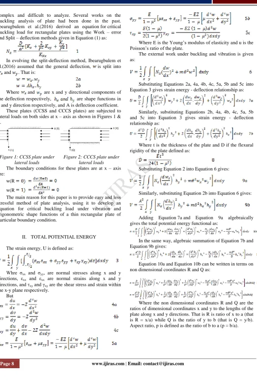
These plates (CCSS and CCCS plates) are subjected to lateral loads on both sides at x – axis as shown in Figures 1 & 2.
Figure 1: CCSS plate under lateral loads
Figure 2: CCCS plate under lateral loads
The boundary conditions for these plates are at x – axis are:
w(R w(R
The main reason for this paper is to provide easy and less stressful method of plate analysis, using it to develop an equation for critical buckling load under vibration and trigonometric shape functions of a thin rectangular plate of particular boundary condition.
II. TOTAL POTENTIAL ENERGY The strain energy, U is defined as:
Whre σxx and σyy, are normal stresses along x and y directions, εxx and εxx are normal strains along x and y directions, and xy and γxy are the shear stress and strain within the x-y plane respectively.
But
Where E is the Young’s modulus of elasticity and u is the Poisson’s ratio of the plate.
The external work under buckling and vibration is given as:
Substituting Equations 2a, 4a, 4b, 4c, 5a, 5b and 5c into Equation 3 gives strain energy - deflection relationship as:
Similarly, substituting Equations 2b, 4a, 4b, 4c, 5a, 5b and 5c into Equation 3 gives strain energy - deflection relationship as:
Where t is the thickness of the plate and D if the flexural rigidity of the plate defined as:
Substituting Equation 2 into Equation 6 gives:
Similarly, substituting Equation 2b into Equation 6 gives:
Adding Equation 7a and Equation 9a algebraically gives the total potential energy functional as:
In the same way, algebraic summation of Equation 7b and Equation 9b gives:
Equation 10a and Equation 10b can be written in terms on non dimensional coordinates R and Q as:
Page 9 www.ijiras.com | Email: [email protected]
GENERAL VARIATION OF THE TOTAL POTENTIAL ENERGY
Minimization of the total potential energy functional with respect to deflection function gives the governing differential equation of forces in equilibrium for the plate. Equation 11a can be modified as:
Where:
Thus minimizing Equation 12a with respect to wx gives:
Carrying out the integration of Equation 14 with respect to Q gives:
Where c1 is a constant.
Similarly, minimizing Equation 12b with respect to wy gives:
Carrying out the integration of Equation 16 with respect to R gives:
Where c2, c3 and c4 are constants.
For cases of pure buckling (that is in the absence of inertia force), Equation 15 and Equation 17 become:
The ready solutions for the integrands of Equation 18 and Equation 19 are:
Where d0, d1, d2,d3, d4, d5, d6 and d7 are integration constants, and
Transforming Equation 20 in trigonometric form gives:
Where a0 = d0, a1 = d1, a2 = d2 + d3 and a3 = id2 – id3 Similarly, transforming Equation 21 in trigonometric form gives:
Where b0 = d4, b1 = d5, b2 = d6 + d7 and b3 = id6 – id7 Substituting Equation 23 and Equation 24 into Equation 2a gives:
DIRECT VARIATION OF THE TOTAL POTENTIAL ENERGY
Formula for analysis is usually obtained after minimization of the total potential energy functional with respect the coefficient of deflection. Hence, minimizing Equation 11b with respect to deflection coefficient gives:
Rearranging Equation 26 gives:
Under free – vibration only, the numerator of Equation 27 is zero. The vibration frequency at free vibration is natural frequency, λ.Thus:
Page 10 www.ijiras.com | Email: [email protected]
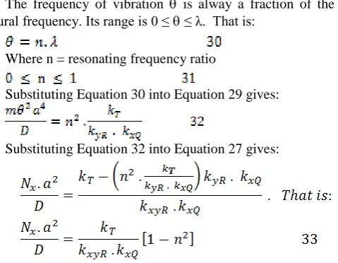
The frequency of vibration is alway a fraction of the natural frequency. Its range is 0 ≤ ≤ λ. That is:
Where n = resonating frequency ratio
Substituting Equation 30 into Equation 29 gives:
Substituting Equation 32 into Equation 27 gives:
This Equation 33 is the formula for calculating the non-dimensional critical buckling load for a rectangular plate under vibration.
III. NUMERICAL ANALYSES
Analyze a classical rectangular thin rectangular isotropic plate with:
Three edges clamped and one edge simply supported (CCCS) using trigonometric function for both .
Two adjacent edges clamped and the other two edges simply supported (CCSS) using trigonometric function for
both .
FOR CCCS PLATE
After satisfying the boundary condition for cccs plate the deflection components obtained are:
Where g1 = 4.49340946
From Equation34a and Equation 34b the shape functions are:
FOR CCCS PLATE
After satisfying the boundary condition for cccs plate the deflection components obtained are:
Where g1 = 4.49340946 and g2 = 4.49340946
From Equations36a and Equation 36b the shape functions are:
With these components of shape functions the stiffness coefficient are calculated and tabulated on Table 1
Table 1: Stiffness coefficients for the two plates
IV. RESULTS AND DISCUSSION
The split deflection total potential energy functional for thin rectangular plate loaded simultaneously with in-plane and inertia loads was formulated as shown on Equation 10a, Equation 10b, Equation 11a and Equation 11b. The equations are so unique such that it can easily be seperated (uncoupled). This fit was evident when general variation was applied on it. The governing equations obtained after general variation with respect to wx and wy were shown on Equation 14 and Equation 16. These equations were reduced to easily solvable equations as shown on Equation 18 and Equation 19. Upon solving Equation 18 and Equation 19, the trigonemetric expressions for wx and wy were obtained. See Equation 23 and Equation 24 for expressions for wx and wy. Equation 25 is the general orthogonal equation of deflection of rectangular plate under buckling load.
Page 11 www.ijiras.com | Email: [email protected]
It is noticed that at zero vibration (n = 0), the critical buckling equations obtained herein are the same with those from earlier studies. However, the equations from the present study differ from the onesobtained by previous study when inerial load is applied (n . This difference accounts for the effect of vibration on buckling of rectangular plates.
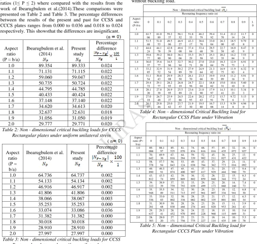
The non-dimensional critical buckling load results of this present work when inertia load was absent (n = 0) for aspect ratios (1≤ P ≤ 2) where compared with the results from the work of Ibearugbulem et al.(2014).These comparisons were presented on Table 2 and Table 3. The percentage differences between the results of the present and past for CCSS and CCCS plates ranges from 0.000 to 0.036 and 0.018 to 0.024 respectively. This showsthat the differences are insignificant.
(n Aspect
ratio (P = b/a)
Ibearugbulem et al. (2014)
Present study
Percentage difference
1.0 89.354 89.333 0.024
1.1 71.131 71.115 0.022
1.2 59.060 59.047 0.022
1.3 50.735 50.724 0.022
1.4 44.795 44.785 0.022
1.5 40.433 40.424 0.022
1.6 37.148 37.140 0.022
1.7 34.620 34.613 0.020
1.8 32.637 32.631 0.018
1.9 31.056 31.050 0.019
2.0 29.777 29.771 0.020
Table 2: Non - dimensional critical buckling loads for CCCS Rectangular plates under uniform unilateral stress ( n
Aspect ratio (P = b/a)
Ibearugbulem et al. (2014)
Present study
Percentage difference
1.0 64.736 64.737 0.002
1.1 54.133 54.134 0.002
1.2 46.916 46.917 0.002
1.3 41.806 41.806 0.000
1.4 38.066 38.067 0.003
1.5 35.253 35.253 0.000
1.6 33.074 33.086 0.036
1.7 31.382 31.382 0.000
1.8 30.018 30.018 0.000
1.9 28.910 28.910 0.000
2.0 27.997 27.997 0.000
Table 3: Non - dimensional critical buckling loads for CCSS Rectangular plates under uniform unilateral stress This paper presents the non-dimensional critical buckling load results of CCSS and CCCS plates when inertia loads were applied (n ≠ 0) for aspect ratios (1≤ p ≤ 2) on Table 4 and table 5 show that as aspect ratio (P = b/a) increases from 1.0 to 2.0 at each resonating frequency ratio / inertia load (n) ranging from 0 to 0.9, non –dimensional critical buckling load decreases, thereby causing the plate to get more slender.
Furthermore, as resonating frequency ratio (n) increases from 0 to 0.9 at each aspect ratio (P = b/a ) ranging from 1.0 to 2.0 , non-dimensional critical buckling load also decreases, thereby weakening the strength of the plate and hence requires less effort to cause it to buckle. At resonating frequency ratio (n = 1) at all aspect ratios, non-dimensional critical buckling load equals zero, [( ) = 0].At this stage, the plate buckles without buckling load.
Table 4: Non – dimensional Critical Buckling load for Rectangular CCSS Plate under Vibration
Table 5: Non – dimensional Critical Buckling load for Rectangular CCCS Plate under Vibration
V. CONCLUSION
The conclusion is drawn that with the close agreement of the results obtained from past and present works at n = 0, it follows that the results of non – dimensional critical buckling load for n – values and their corresponding aspect ratios presented in Table 4 and Table 5 (for which there are no other existing results to compare with in literature) are also correct.
Non – dimensional critical buckling load ( ) Resonating frequency ratio (n) Aspect
ratio (P=b/a )
0 0.1 0.2 0.3 0.4 0.5 0.6 0.7 0.8 0.9 1.
0
1.0 61.7
06 61.0 89 59.2 37 56.1 52 51.8 33 46.2 79 39.4 92 31.4 70 22.2 14 11.7 24 0
1.1 51.5
68 51.0 53 49.5 06 46.9 27 43.3 17 38.6 76 33.0 04 26.3 00 18.5 65 9.79 8 0
1.2 44.6
24 44.1 78 42.8 39 40.6 08 37.4 84 33.4 68 28.5 59 22.7 58 16.0 65 8.47 9 0
1.3 39.6
77 39.2 80 38.0 90 36.1 06 33.3 29 29.7 58 25.3 93 20.2 35 14.2 84 7.53 9 0
1.4 36.0
37 35.6 77 34.5 96 32.7 94 30.2 71 27.0 28 23.0 64 18.3 79 12.9 73 6.91 1 0
1.5 33.2
85 32.9 52 31.9 54 30.2 89 27.9 59 24.9 64 21.3 02 16.9 75 11.9 83 6.32 4 0
1.6 31.1
54 30.8 43 29.9 08 28.3 50 26.1 70 23.3 66 19.9 39 15.8 89 11.2 16 5.91 9 0
1.7 29.4
72 29.1 77 28.2 93 26.8 19 24.7 56 22.1 04 18.8 62 15.0 31 10.6 10 5.60 0 0
1.8 28.1
20 27.8 39 26.9 95 25.5 89 23.6 21 21.0 90 17.9 97 14.3 41 10.1 23 5.34 3 0
1.9 27.0
18 26.7 48 25.9 37 24.5 86 22.6 95 20.2 63 17.2 91 13.7 79 9.72 6 5.13 3 0
2.0 26.1
07 25.8 46 25.0 62 23.7 57 21.9 30 19.5 80 16.7 08 13.3 14 9.39 8 4.96 0 0
Non – dimensional critical buckling load ( ) Resonating frequency ratio (n) Aspect
ratio (P= b/a)
0 0.1 0.2 0.3 0.4 0.5 0.6 0.7 0.8 0.9 1.0
1.0 89.
088 88.1 97 85. 525 81. 070 74. 834 66. 816 57. 016 45. 435 32. 072 16. 927 0
1.1 70.
642 69.9 36 67. 816 64. 284 59. 339 52. 982 45. 211 36. 027 25. 431 13. 422 0
1.2 58.
378 57.7 94 56. 043 53. 124 49. 038 43. 784 37. 362 29. 773 21. 016 11. 092 0
1.3 49.
890 49.3 91 47. 874 45. 400 41. 907 37. 417 31. 929 25. 444 17. 960 9.4 79 0
1.4 43.
812 43.3 74 42. 059 39. 869 36. 802 32. 859 28. 040 22. 344 15. 772 8.3 24 0
1.5 39.
333 38.9 39 37. 759 35. 793 33. 039 29. 499 25. 173 20. 060 14. 160 7.4 73 0
1.6 35.
948 35.5 89 34. 511 32. 713 30. 197 26. 961 23. 007 18. 334 12. 941 6.8 30 0
1.7 33.
336 33.0 03 32. 002 30. 336 28. 002 25. 002 21. 335 17. 001 12. 001 6.3 34 0
1.8 31.
281 30.9 68 30. 030 28. 466 26. 276 23. 461 20. 020 15. 953 11. 261 5.9 43 0
1.9 29.
637 29.3 41 28. 452 26. 970 24. 895 22. 228 18. 968 15. 115 10. 669 5.6 31 0
2.0 28.
Page 12 www.ijiras.com | Email: [email protected]
Hence, the present equations developed are reliable and are recommended for use in classical analysis. For future studies, it is recommended that buckling analysis of a thin rectangular plate under vibration outside these aspect ratios should be carried out using this present method.
REFERENCES
[1] Erdem , C. lmrak and Ismail Gerdemeli (2007). The problem of isotropic rectangular plate with four clamped edges. S-adhan-a. Vol. 32, part 3, pp. 181 – 186.
[2] Ezeh, J. C., Ibearugbulem, O. M., Njoku, K.O., and Ettu, L.O. (2013). Dynamic Analysis of Isotropic SSSS plate using Taylor Series Shape Function in Galerkin’s Functional. International Journal of Emerging Technology and Advanced Engineering, 3 (5) : 372 – 375.
[3] Hutchinson, J.R. (1992). On the bending of rectangular plates with two opposite edges simply supported . J. Appl .Mech. Trans. ASME 59:679 – 681.
[4] Ibearugbulem, O.M. (2014). Using the product of two mutually perpendicular truncated polynomial series as shape function for rectangular plate analysis. International Journal of Emerging Technologies and Engineering ( IJETE). ISSN: 2348 – 8050, ICRTIET – 2014. Conference proceeding, 30th – 31st August 2014, 1- 4 [5] Ibearugbulem, O.M., Ezeh, J.C. and Ettu, L.O. (2014).
Energy Methods in Theory of Rectangular plates (Use of Polynomial Shape Functions), Liu House of Excellence Venture – Imo State, Nigeria.
[6] Ibearugbulem, O. M., Ibearugbulem, C.N., HabibMomoh and Asomugha, U.C. (2016). Buckling Analysis of Rectangular Plate by Split – Deflection Method. International Journal of Scientific and Research Publications, Vol. 3, Issue 5.
[7] Jiu, Hiu Wu, A.Q. Liu, and H. L. Chen (2007). Exact Solutions for Free – Vibration Analysis of Rectangular Plates. Journal of Applied Mechanics. Vol. 74: PP 1247 -1251
[8] Lal, R., Kumar, Y. & Gupta, U.S. (2009) Transverse Vibrations of Non – Homogenous Rectangular Plates of Uniform Thickness using Boundary Characteristics Orthogonal Polynomials. Int .J. of Appl .Maths and Mech., 6 (14), 93 -109.
[9] Lee, S. J. (2004). Free- Vibration Analysis of plates by using a Four- Note Finite Element Formulated with Assumed Natural Transverse Shear Strain. Journal of Sound and Vibration, 278, 657 – 684.
[10] Misra, R.K.(2012). Static and Dynamic Analysis of Rectangular Plate using Multiquadric Radial Basic Function. International Journal of Management, I .T and Engineering, 2 (8), 166 – 178
[11] Szilard, R. (2004).Theories and Applications of Plate Analysis. New Jersey: John Wiley & sons Inc.
[12] Shu, C., Wu, W.X., Ding, H. &Wang C.M. (2007). Free vibration Analysis of Plates using Least – Square – Based Finite Difference Method. Comput. Methods Appl. Mech. Engrg., 196, 1330 – 1343.
[13] Taylor, R.L. and Govindjee, S.(2004). Solution of Clamped Rectangular Plate Problems, Communications in Numerical Methods in Engineering, 20 : PP. 757 – 765. [14] Ugural, A.C.(1999). Stresses in Plates and Shells, 2nd ed.
Singapore: McGraw- hill
[15] Ventsel, E. and T. Krauthammer (2001). Thin Plates and Shells: Theory, Analysis and Applications. New York: Marcel Dekker.
[16] Wang, C.M., Y.C. Wang and J.N. Reddy (2002). Problems and remedy for the Ritz method in determining stress resultant of corner supported rectangular plates . Comput.Struct. 80:145 – 154.
[17] Werfalll, N.M. &Karaid, A.A. (2005). Free – Vibration Analysis of Rectangular Plates using Galerkin – Based Finite Element Method. International of Mechanical Engineering, 2(2), 59- 67.