517
Mbahaotu, Godsaveus O
1, ETJ Volume 04 Issue 01 January 2019
Volume 04 Issue 01 January- 2019, Page No.-517-522
DOI:10.31142/etj/v4i1.02, I.F. - 4.449
© 2019, ETJ
Analysis of SSSS and CSCS Rectangular Plates under both Lateral and
In-Plane Loads Using Split Deflection Method
Mbahaotu, Godsaveus O
1., Ndububa E. E.
2, Ibearugbulem, O. M
3., Nwosu, Onyebuchi
4 1,2,4Department of Civil Engineering, University of Abuja3Department of Civil Engineering, Federal University of Technology, Owerri
Abstract:This paper presents rectangular plate analysis under both lateral and in-plane loads using split deflection method. Thin rectangular plate with primary and secondary in-plane dimensions a and b and thickness t was analyzed in this research. The plates analyzed are ssss plate, simply supported at all edges and cscs plate, simply supported on two opposite edges and clamped on other edges. The total potential energy functional of the plate is minimized with respect to deflection. This gives governing equation, which was solved using split deflection to obtain general equation for deflection. It is also minimized with respect to coefficient of deflection to obtain the formula for the deflection coefficient. The work satisfies the boundary conditions the two plates and obtained unique shape functions for them. Numerical values of the coefficients of deflection and the center deflections of the two plates are determined in the absence and also in the presence of in-plane loads. The results show that the maximum percentage differences recorded for ssss and cscs plates, in the absence of in-plane load, with previous results are 4.86% and 5.15%. It is observed that it is not advisable to work with plate with in-plane load exceeding the critical buckling load.
Keywords:
split deflection, rectangular plate, in-plane load, critical buckling load, centre deflection, potential energyI. INTRODUCTION
The common energy methods used in the past for analysis of rectangular plates for isotropic cases are Ritz, Galerkin and work-error method ([1], [2]). These previous methods used coupled orthogonal deflection function ([3] [4], [5], [6], [7], [8], [9], [2]]). It is this coupled form that makes the solution of the resulting governing equation tedious to arrive at, after performing general variation on the total potential energy functional. The few ones that employed split deflection function did not treat a bending of plate problem, which involves both lateral and in-plane loads simultaneously ([2], [9]). This present research is based on the use of split deflection method of rectangular plate analysis, to analyze rectangular plate subjected to both lateral and in- plane load simultaneously .In this method, deflection functions are separated into x and y components of deflection. These components of deflections, which are independent distinct functions, may be represented as “w” = wx wy (where w is deflection, and wx and wy are
deflection components in x and y direction respectively). Each of the deflection components is product of shape function and coefficient of the deflection. That is wx = Ax . hx and wy = Ay .
hy.
II. FORMULATION OF TOTAL POTENTIAL ENERGY
EQUATION BASED ON SPLIT DEFLECTION
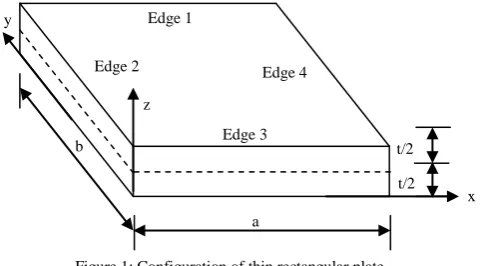
The plate configuration is as shown on Figure 1.
The edges of the plate are numbered systematically in anti-clockwise direction. edges 1 and 3 define y direction whereas edges 2 and 4 define x direction. Lenghts of the plate along x, y and z directions are a, b and t respectively. This formulation follows the steps: kinematics, constitutive equations, strain energy, external work and total potential energy. Meanwhile, the split-deflection equation is:
A. Kinematics
From the third Kirchhoff's assumption, the following hold:
b
a
x z
Edge 1
Edge 2
Edge 3 Edge 4 y
Figure 1: Configuration of thin rectangular plate t/2
Method”
518
Mbahaotu, Godsaveus O
1, ETJ Volume 04 Issue 01 January 2019
Where u0 and v0 re integration constants. Substituting equation
1a into equations 2 and 3 gave:
Differentiation equation 2b and 3b with respect to either x or y resulted the following engineering strain components:
A. In-plane constitutive equations
Reference [9] gave the in-plane constitutive equations for thin rectangular plates as:
Where: E, x, y, xy and µ are Young's elastic modulus, normal strain in x direction, normal strain in y direction, shear strain within xy plane and Poisson's ratio respectively. The normal stress in x direction, normal stress in y direction and the shear stress within xy are respectively designated as x, y and
xy.
Substituting equations 4, 5 and 6 into equations 7, 8 and 9 where appropriate gives:
B. Strain energy
The strain energy is commonly defined as given in equation 13 as:
Substituting equations 4, 5, 6, 10, 11 and 12 into equation 13 gives:
That is:
Substituting equation 1b into equation 14 gives:
In terms of non dimensional coordinates, R and Q, equation is is rewritten as:
Where is the ratio of length of plate in y direction to length in x direction (α = b/a).
In symbolized form, equation 17 is written as:
C. External Work equations
The equations for external works due to lateral load and buckling load were respectively given by Reference [2] as:
Method”
519
Mbahaotu, Godsaveus O
1, ETJ Volume 04 Issue 01 January 2019
Substituting equation 1b into equations 19 and 20and writing the outcomes in non dimensional coordinates and in symbolized form gives:
Where:
D. Total potential energy equation
Total potential energy equation is the algebraic summation of the strain energy (internal resistant work) and external work. Thus, subtracting equations 21 and 22 from equation 18 gives:
III. FORMULA FOR DEFLECTION COEFFICIENT FOR A
RECTANGULAR PLATE UNDER BOTH LATERAL
AND IN-PLANE LOADS
To get the formula for deflection coefficient for a rectangular plate under both lateral and in-plane loads, the total potential energy equation was minimized with respect to the coefficient. This is otherwise called direct variation of total potential energy. This minimization gives:
Rearranging equation 24 gave:
Where:
The in-plane load when the plate has buckled under the action of only in-plane load is called the critical buckling load. It is denoted as Nc. For the case of only in-plane load at
buckling, the denominator of equation 25 is equal to zero and the in-plane load is replaced with critical buckling load. That is:
Rearranging equation 27 gives:
Let the range of the in-plane load be in a range as shown:
Furthermore, let the in-plane load be a fraction of the critical buckling load defined as:
This means that range of n is:
Substituting equation 30 into equation 25 gives:
Substituting equation 28 into equation 32 gives:
Where:
Substituting 1b into equation 32 gives the deflection parameter as:
IV. NUMERICAL EXAMPLES
Determine the center deflection of ssss and cscs plates under combined actions of lateral load and in-plane load. The components of shape function of deflections to be used are the ones given by Reference [7]:
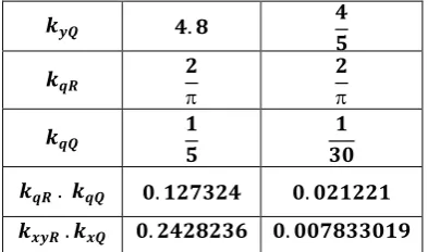
With these components of shape functions the stiffness coefficient are calculated and tabulated on Table I
TableI: Stiffness Coefficients For The Two Plate
ssss
cscs
Method”
520
Mbahaotu, Godsaveus O
1, ETJ Volume 04 Issue 01 January 2019
At the center of the plates, R = Q = 0.5.
That is:
That is:
The comparison of the centre defection for a case where axial load is zero and the result from earlier scholars was by simple percentage difference. The percentage difference equation used is:
Where abs means absolute value, wp means deflection from
present study and wE is the deflection from earlier scholars.
V. RESULTS AND DISCUSIONS
The result of this present study is presented as follows; Stiffness coefficients for the two rectangular plates are presented on Table I, Centre deflections, wc (qa4/D) for ssss
and cscs plates, when in-plane load is absent for different aspect ratios are presented on Table II and Table III respectively. In the presence of in-plane, the centre deflections of two rectangular plate were determined the values for various in-plane loads are present on Table IV and Table V for ssss and cscs plates respectively. A critical look at Table II shows a maximum percentage difference of 4.86% when the present
results for ssss plates are compared with those of reference [10]. It is good to note that the methode used herein is different from the methode used by reference [10]. Again, it is observed that the maximum percentage difference between the results for cscs plate in this present study and those of reference [10] is 5.15%. This is readily seen on Table III. The maximum percentage difference encountered indicates that the difference is not significant, hence justified the credibility of the split deflection method used in this present study. The center deflections of the two plates for various amount of ratio of in-plane load and critical buckling load and for various aspect ratio were determined, the result indicated that in-plane compression load increases deflectinon of the plates. The increase is gradual from n = 0 to n = 0.3. Between n = 0.4 and n = 0.5 the increase is moderate. However, the increase is rapid when n is more than 0.5. Thus, it is advisable to treat a plate as a plate subject to both in-plane load and lateral whenever the in-plane load exceeds 30% of the critical buckling load of the plate. Furthermore, engineers should as much as possible avoid a situation where in-plane load exceeds 50% of critical buckling load. Based on the results of this present study, the split deflection method is justified as a veritable method to analyze rectangular plate under both lateral and in- plane loads.
TableII: Centre Deflection of SSSS Plate
b/a Wc present study
Wc
Reference [10]
Percentage difference 1 0.004148 0.00406 2.17 1.1 0.004974 0.00485 2.56 1.2 0.00578 0.00576 0.35 1.3 0.00655 0.00638 2.66 1.4 0.007277 0.00705 3.21 1.5 0.007955 0.00772 3.03 1.6 0.008583 0.0083 3.40 1.7 0.00916 0.00883 3.74 1.8 0.009692 0.00931 4.09 1.9 0.010178 0.00974 4.50 2 0.010623 0.01013 4.86
Table III: Centre deflection of CSCS plate b/a Wc
present study
Wc
Reference [10]
Method”
521
Mbahaotu, Godsaveus O
1, ETJ Volume 04 Issue 01 January 2019
Table IV; Center deflection of SSSS plate for various aspect ratios and in-plane loads, wc (qa4/D)
b/a n = 0 n = 0.1 n = 0.2 n = 0.3 n = 0.4 n = 0.5 n = 0.6 n = 0.7 n = 0.8 n = 0.9 1 0.004148 0.004609 0.005185 0.005926 0.006914 0.008296 0.01037 0.013827 0.020741 0.04148 1.1 0.004974 0.005527 0.006218 0.007106 0.008291 0.009949 0.012436 0.01658 0.024872 0.04974 1.2 0.00578 0.006422 0.007225 0.008257 0.009633 0.01156 0.01445 0.019266 0.028899 0.0578 1.3 0.00655 0.007278 0.008188 0.009358 0.010917 0.0131 0.016376 0.021834 0.032752 0.0655 1.4 0.007277 0.008085 0.009096 0.010395 0.012128 0.014554 0.018192 0.024256 0.036384 0.07276 1.5 0.007955 0.008839 0.009943 0.011364 0.013258 0.015909 0.019887 0.026516 0.039773 0.07954 1.6 0.008583 0.009536 0.010728 0.012261 0.014304 0.017165 0.021456 0.028608 0.042913 0.08582 1.7 0.00916 0.010179 0.01145 0.013087 0.015268 0.018322 0.022902 0.030537 0.045805 0.0916 1.8 0.009692 0.010769 0.012115 0.013846 0.016153 0.019384 0.024230 0.032306 0.048460 0.09691 1.9 0.010178 0.011309 0.012723 0.01454 0.016964 0.020356 0.025446 0.033927 0.050891 0.10178 2 0.010623 0.011803 0.013279 0.015176 0.017705 0.021246 0.026557 0.035410 0.053115 0.10622
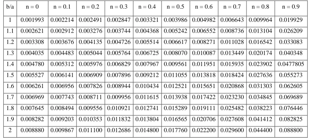
Table V. Center deflection of cscsplate for various aspect ratios and in-plane loads, wc (qa 4
/D)
b/a n = 0 n = 0.1 n = 0.2 n = 0.3 n = 0.4 n = 0.5 n = 0.6 n = 0.7 n = 0.8 n = 0.9 1 0.001993 0.002214 0.002491 0.002847 0.003321 0.003986 0.004982 0.006643 0.009964 0.019929 1.1 0.002621 0.002912 0.003276 0.003744 0.004368 0.005242 0.006552 0.008736 0.013104 0.026209 1.2 0.003308 0.003676 0.004135 0.004726 0.005514 0.006617 0.008271 0.011028 0.016542 0.033083 1.3 0.004035 0.004483 0.005044 0.005764 0.006725 0.008070 0.010087 0.013449 0.020174 0.040348 1.4 0.004780 0.005312 0.005976 0.006829 0.007967 0.009561 0.011951 0.015935 0.023902 0.0477805 1.5 0.005527 0.006141 0.006909 0.007896 0.009212 0.011055 0.013818 0.018424 0.027636 0.055273 1.6 0.006261 0.006956 0.007826 0.008944 0.010434 0.012521 0.015651 0.020868 0.031303 0.062605 1.7 0.006969 0.007743 0.008711 0.009956 0.011615 0.013938 0.017422 0.023230 0.034845 0.069689 1.8 0.007645 0.008494 0.009556 0.010921 0.012741 0.015289 0.019111 0.025482 0.038223 0.076446 1.9 0.008282 0.009203 0.010353 0.011832 0.013804 0.016565 0.020706 0.027608 0.041412 0.082825 2 0.008880 0.009867 0.011100 0.012686 0.014800 0.017760 0.022200 0.029600 0.044400 0.088800
REFERENCES
1. Njoku, K. O., Ezeh, J. C., Ibearugbulem, O. M., Ettu, L. O., and Anyaogu, L. (2013). Free vibration analysis of thin rectangular isotropic cccc plate using Taylor series formulated shape function in Galerkin’s method. Academic Research International, vol 4, No. 4, pp. 126 – 132.
2. Ibearugbulem, O. M., Ibeabuchi, V. I., and Njoku, K. O. (2014). Buckling analysis of ssss stiffened rectangular isotropic plates using work principle approach. Intl. Journal of Innovative Research and Development, vol. 3, issue 11, pp. 169 – 176.
3. Ugural, A. C. (1999). Stresses in plates and shells (2nd Ed.). Singapore: McGraw-hill
4. Ventsel, E. And Krauthammer, T. (2001). Thin Plates and Shells: Theory, Analysis and Applications. New York: Marcel Dekker
5. Szilard, R. (2004). Theories and Applications of plate analysis (Classical, Numerical and Engineering Methods). New Jersey: John Wiley & Sons.
6. Ezeh, J. C., Ibearugbulem, O. M., Njoku, K. O. and Ettu, L. O. (2013). Dynamic analysis of isotropic ssss plate using Taylor series shape function in Galerkin’s functional. International Journal of Emerging Technology and Advanced Engineering, vol. 3, issue 5, pp. 372 – 375.
7. Ibearugbulem , O. M (2016).. “Note on rectangular plate analysis.” Germany: Lambert Academic Publishing Omni Scriptum GmbH & Co. KG. ISBN: 978-3-330-01636-1
Method”
522
Mbahaotu, Godsaveus O
1, ETJ Volume 04 Issue 01 January 2019
Federal University of Technology Owerri (un-published)
9. Ibearugbulem , O. M., Ibearugbulem , C. N., Momoh, H., and Asomugha, A. U.. (2016). “Split – deflection method of classical rectangular plate analysis.” International journal of Scientific
and research publication, vol 6, issue. 5, ISSN 2250 – 3153, 2016
10. Timoshenko, S. P. and Woinowsky- Krieger , S. (1959). “Theory of plates and shells”.New York;