University of Pennsylvania
ScholarlyCommons
Publicly Accessible Penn Dissertations
1-1-2014
Grasping and Assembling with Modular Robots
Jungwon Seo
University of Pennsylvania, [email protected]
Follow this and additional works at:http://repository.upenn.edu/edissertations Part of theRobotics Commons
This paper is posted at ScholarlyCommons.http://repository.upenn.edu/edissertations/1436
For more information, please [email protected].
Recommended Citation
Seo, Jungwon, "Grasping and Assembling with Modular Robots" (2014).Publicly Accessible Penn Dissertations. 1436.
Grasping and Assembling with Modular Robots
Abstract
A wide variety of problems, from manufacturing to disaster response and space exploration, can benefit from robotic systems that can firmly grasp objects or assemble various structures, particularly in difficult, dangerous environments. In this thesis, we study the two problems, robotic grasping and assembly, with a modular robotic approach that can facilitate the problems with versatility and robustness.
First, this thesis develops a theoretical framework for grasping objects with customized effectors that have curved contact surfaces, with applications to modular robots. We present a collection of grasps and cages that can effectively restrain the mobility of a wide range of objects including polyhedra. Each of the grasps or cages is formed by at most three effectors. A stable grasp is obtained by simple motion planning and control. Based on the theory, we create a robotic system comprised of a modular manipulator equipped with customized end-effectors and a software suite for planning and control of the manipulator.
Second, this thesis presents efficient assembly planning algorithms for constructing planar target structures collectively with a collection of homogeneous mobile modular robots. The algorithms are provably correct and address arbitrary target structures that may include internal holes. The resultant assembly plan supports parallel assembly and guarantees easy accessibility in the sense that a robot does not have to pass through a narrow gap while approaching its target position. Finally, we extend the algorithms to address various symmetric patterns formed by a collection of congruent rectangles on the plane.
The basic ideas in this thesis have broad applications to manufacturing (restraint), humanitarian missions (forming airfields on the high seas), and service robotics (grasping and manipulation).
Degree Type Dissertation
Degree Name
Doctor of Philosophy (PhD)
Graduate Group
Mechanical Engineering & Applied Mechanics
First Advisor Vijay Kumar
Second Advisor Mark Yim
Keywords
GRASPING AND ASSEMBLING WITH MODULAR ROBOTS
Jungwon Seo
A DISSERTATION
in
Mechanical Engineering and Applied Mechanics
Presented to the Faculties of the University of Pennsylvania in Partial
Fulfillment of the Requirements for the Degree of Doctor of Philosophy
2014
Vijay Kumar, Supervisor of Dissertation
Professor of Mechanical Engineering and Applied Mechanics
Mark Yim, Co-Supervisor of Dissertation
Professor of Mechanical Engineering and Applied Mechanics
Prashant Purohit, Graduate Group Chairperson
Associate Professor of Mechanical Engineering and Applied Mechanics
Dissertation Committee:
GRASPING AND ASSEMBLING WITH MODULAR ROBOTS
COPYRIGHT
2014
Acknowledgments
First and foremost, I would like to thank my advisors, Dr. Vijay Kumar and Dr.
Mark Yim, for their guidance, inspiration, encouragement, passion, and patience
throughout my graduate studies. Without their support, it would have been
im-possible for me to get through academic and personal challenges. I would also like
to thank Dr. Camillo Taylor and Dr. Nicolas Hudson for serving on my thesis
com-mittee and providing valuable comments and insights. Special thanks to my friends
and the staff of MEAM, MRSL, ModLab, and GRASP. I am enormously grateful
to the love and support of my parents, especially in loving memory of my father.
ABSTRACT
GRASPING AND ASSEMBLING WITH MODULAR ROBOTS
Jungwon Seo
Vijay Kumar
Mark Yim
A wide variety of problems, from manufacturing to disaster response and space
exploration, can benefit from robotic systems that can firmly grasp objects or
as-semble various structures, particularly in difficult, dangerous environments. In this
thesis, we study the two problems, robotic grasping and assembly, with a modular
robotic approach that can facilitate the problems with versatility and robustness.
First, this thesis develops a theoretical framework for grasping objects with
customized effectors that have curved contact surfaces, with applications to modular
robots. We present a collection of grasps and cages that can effectively restrain the
mobility of a wide range of objects including polyhedra. Each of the grasps or cages
is formed by at most three effectors. A stable grasp is obtained by simple motion
planning and control. Based on the theory, we create a robotic system comprised
of a modular manipulator equipped with customized end-effectors and a software
suite for planning and control of the manipulator.
Second, this thesis presents efficient assembly planning algorithms for
construct-ing planar target structures collectively with a collection of homogeneous mobile
structures that may include internal holes. The resultant assembly plan supports
parallel assembly and guarantees easy accessibility in the sense that a robot does
not have to pass through a narrow gap while approaching its target position.
Fi-nally, we extend the algorithms to address various symmetric patterns formed by a
collection of congruent rectangles on the plane.
The basic ideas in this thesis have broad applications to manufacturing
(re-straint), humanitarian missions (forming airfields on the high seas), and service
Contents
I
Introduction and Background
1
1 Introduction 2
1.1 Problem Statement . . . 4
1.2 Thesis Contributions . . . 6
1.3 Vision . . . 7
1.4 Organization of This Work . . . 9
2 Literature Review 11 2.1 Robotic Grasping . . . 11
2.1.1 Prehensile Approach . . . 12
2.1.2 Non-Prehensile Approach . . . 14
2.2 Assembly Planning . . . 16
2.2.1 Assembly Sequencing . . . 16
2.2.2 Beyond Traditional Assembly Sequencing . . . 17
2.3.1 Self-Assembly . . . 18
2.3.2 Locomotion . . . 20
2.3.3 Manipulation . . . 20
II
Grasping with Modular Robots
22
3 Preliminaries: Caging and Grasping 23 3.1 Caging . . . 233.2 Contact . . . 24
3.3 Grasping . . . 26
3.4 Clamping . . . 27
4 Immobilizing Objects with Curved Effectors 28 4.1 Immobilizing with Three Point Contacts . . . 29
4.2 Immobilizing with a Point, a Line, and a Planar contact . . . 30
4.3 Immobilizing with Two Line Contacts . . . 32
4.4 Analysis . . . 33
5 Caging Objects with Curved Effectors 37 5.1 Analytical Method . . . 39
5.1.1 Caging on a Vertex-Vertex Pair . . . 39
5.1.2 Caging on a Vertex-Face Pair . . . 40
5.2 Empirical Method . . . 43
5.3 Analysis . . . 45
6 Synthesizing Grasps and Cages 48 7 Extending Our Theory 53 8 A Modular Approach to Whole-Arm Grasping 59 8.1 Approach and Algorithm . . . 60
8.2 Implementing Whole-Arm Grasping . . . 65
8.2.1 Hardware . . . 65
8.2.2 Software . . . 66
8.3 Experiments . . . 69
8.3.1 End-Effector Positioning . . . 70
8.3.2 Whole-Arm Grasping . . . 71
III
Assembling with Modular Robots
76
9 Approach to Assembling Planar Structures with Rectangular Mod-ules 77 9.1 Hardware Framework . . . 789.1.1 Shape and Locomotion . . . 79
9.1.2 Docking Capability . . . 79
9.3 Approach . . . 84
10 Algorithm for Parallel Assembly 87
10.1 Algorithm . . . 87
10.2 Instructions on Applying Algorithm 3 . . . 92
10.3 Analysis . . . 93
11 Algorithm for Target Structures with Holes 99
11.1 Algorithm . . . 99
11.2 Analysis . . . 105
12 Implementation and Experiment 110
12.1 Assembly Planner . . . 110
12.2 Experiment 1: Assembly Planning . . . 111
12.3 Experiment 2: Assembling Robotic Boats . . . 115
13 Extension to Other Patterns 118
IV
Conclusion
125
14 Conclusion 126
14.1 Summary of Contributions . . . 126
14.2 Future Work . . . 128
List of Tables
8.1 The results of Experiments 1, 2, and 3 are summarized in the first,
second, and third column, respectively. Each entry of the column
shows a triple of numbers that represent x-, y-, and z-directional
positioning errors, with respect to the reference frame shown in
Fig-ure 8.6, measFig-ured in millimeters with the number of times it appeared. 72
8.2 The results of Experiments 4, 5, and 6. . . 73
8.3 The time frame to perform the two phases of whole-arm grasping. . 75
12.1 The results of assembly planning experiments. For the optimal plans,
we iterated over all member sites for the USA and harbor examples;
List of Figures
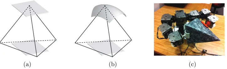
1.1 The tetrahedron is grasped by (a) the two planar effectors, (b) the
planar and concave effectors, and (c) the modular manipulator. . . 5
1.2 (a) Robots, depicted as solid, black rectangles, are being assembled
into the planar structure, which locally looks like the common brick
wall shown in (b). (c) A landing platform autonomously assembled
with robotic boats. . . 6
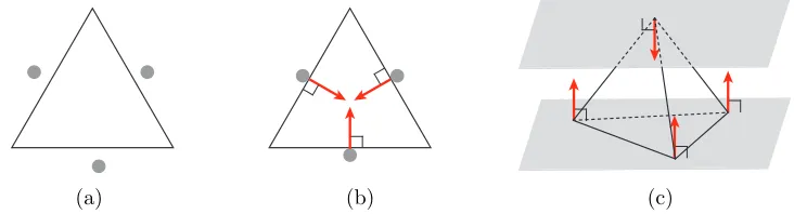
3.1 (a) Caging the triangle with the three point effectors. (b)
Immobi-lizing the regular triangle with the three point effectors located at
the center of each edge. (c) Clamping the tetrahedron with the two
planar effectors contacting the vertex-face pair. The red arrows are
involved unit contact wrenches under the assumption of frictionless,
rigid, unilateral contact in (b), (c), and all upcoming figures. . . 24
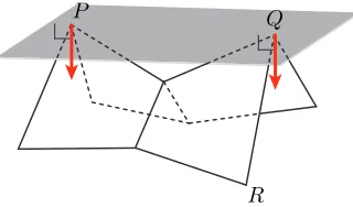
3.2 The plane is contacting the virtual edge P Qbetween the two “real”
4.1 (a) (P, Q, R) is a vertex-vertex-vertex triple where three point
con-tacts immobilizing the octahedron can be made. (b) The front view
of the octahedron with the two curved effectors contactingP and Q.
The effectors can locally be embedded inside the ball whose diameter
has endpoins P and Q, except for the points contacting P and Q.
(c) An immobilizing grasp by the effectors with a spherical surface.
(d) An immobilizing grasp by the cone-shaped effectors. . . 29
4.2 (a) (P, P S,QRST) is a vertex-edge-face triple where a point, a
line, and a planar contact immobilizing the pyramid can be made.
(b) The front view of the object with the two effectors contacting the
vertex and the face. The curved effector contacting the vertex, P,
can locally be embedded inside the space between the two supporting
planes, except for the point contactingP. (c) An immobilizing grasp
by the effectors with a spherical, a cylindrical, and a planar surface.
(d) An immobilizing grasp where the point (line) contact is made by
4.3 (a) (P Q, RS) is an edge-edge pair where two line contacts
immobi-lizing the tetrahedron can be made. (b) The front view of the object
with the two curved effectors contacting the edges. The curved
ef-fectors can locally be embedded inside the space between the two
supporting planes (except for the line segments contacting the
ob-ject). (c) An immobilizing grasp by the effectors with a cylindrical
surface. (d) An immobilizing grasp by the two V-shaped effectors. . 32
5.1 Cages of two curved effectors. The inscribed shapes colored red (the
line segment in (a), the right circular cone in (b), and the
tetrahe-dron in (c)) are used to establish sufficient conditions for caging in
Section 5.1. . . 38
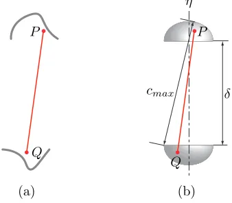
5.2 (a) The planar view showsP andQcontained in the curved effectors.
(b) A cage of two hemispherical effectors. . . 39
5.3 (a) The planar view shows the red cone in Figure 5.1b is containted
between the two parallel planar effectors. (b) The curved and
pla-nar effectors are caging the cone. (c) A cage of the hemispherical
and planar effectors. The hemispherical effector is only allowed to
5.4 (a) The planar view shows the red tetrahedron in Figure 5.1c is
con-tained between the two parallel planar effectors. (b) The planar
effector at the bottom and the curved effector are caging the
tetrahe-dron. (c) A cage of the two half-cylindrical effectors. They are only
allowed to translate along their common perpendicular, η. . . 42
5.5 Establishing cages in an empirical manner. (a), (b) Caging on a
vertex-vertex pair. (c), (d) Caging on a vertex-face pair. (e), (f)
Caging on an edge-edge pair. . . 44
6.1 The label for the edge-edge pair, (P Q, RS). . . 50
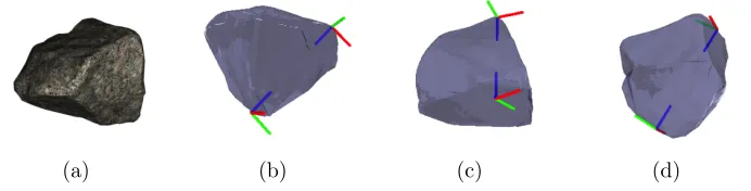
6.2 (a) A polyhedral rock model with 1,000 faces (courtesy: Malcolm
Lambert, Intresto Pty Ltd.). (b), (c), and (d) respectively show a
vertex-vertex pair, a vertex-face pair, and an edge-edge pair found
by running our algorithm. The reference frames are positioned and
oriented such that the origin is at the contact position and thez-axis
is along the contact normal, according to the label of each element
pair. . . 51
7.1 (a) An immobilizing grasp at an antipodal vertex-edge pair with the
cone- and V-shaped effectors. The vertex, O, is the origin of the
reference frame whosex-axis is parallel to the edge AB andy-axis is
collinear to ξ. (b) An immobilizing grasp at an antipodal edge-face
7.2 The polygon is immobilized by (a) two point contacts at the
vertex-vertex pair determining the diameter (b) a point and a line contact at
the vertex-edge pair determining the width. (c) The polygon is caged
by two point effectors. If the effectors were contacting the concave
vertices, the polygon would be immobilized. . . 57
8.1 Two whole-arm grasps by the PR2. . . 60
8.2 At the configurationcp (in grey), the curved end-effectors of the
arm-chain are caging the object. The wireframe shows the configurations
of the end-effectors at cs, after the squeezing motion. . . 62
8.3 (a) Two types of CKbot modules providing one rotational degree of
freedom. The left one (swivel joint) provides continuous rotation;
the right one (elbow joint) is limited to 180 degrees rotation. (b)
Two 3-d.o.f. planar arms and a 3-d.o.f. spine between them. (c) A
finished two-armed robot. (d) 3D printed end-effectors that can be
docked to the robot. . . 65
8.5 (a) The planar armchain is composed of two planar 3R manipulators
connected to the base (the longest link). At the configuration cp
(in grey), the end-effectors are caging the object. cs shows a target
configuration which a squeezing motion can aim at. (b) Around each
link pxpy of the planar 2R manipulator, two level sets of d(x,pxpy)
are shown. Such a level set allows us to model the actual collision
hull of a link that may not be a line segment. . . 68
8.6 The figure illustrates the results of Experiments 1, 2, and 3. In (a),
(b), and (c), the simulated robot in the upper panel shows the target
configuration for Experiments 3, 1, and 2, respectively; the real robot
was controlled to the targets as shown in the lower panels. The ‘4’,
‘’, and ‘’ marks represent data points showing the actual, final
positions of the tip of the right arm in Experiments 3, 1, and 2,
respectively, with respect to the reference frame attached at the tip
of the right arm of the simulated robots (the red, green, and blue
axes are the x-, y-, and z-axis of the frame). In principle, the data
points were expected to coincide with the origin of the frame (see the
‘∗’ mark at the top of the graph). . . 71
8.7 (a) A torus-shaped end-effector. (b) A cylindrical end-effector; in
the model, material usage was minimized to reduce weight and cost.
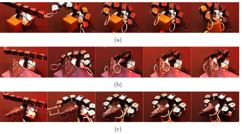
8.8 (a) The robot is grasping the box with the two torus-shaped
end-effectors that can cage and grasp the vertex-vertex pair. (b) The
robot is grasping the tetrahedral object also with the two
torus-shaped end-effectors that can cage and grasp the vertex-face pair;
one of the torus-shaped effectors was used to contact the face. (c)
The robot is grasping the tetrahedral object with the two cylindrical
end-effectors that can cage and grasp the edge-edge pair. . . 74
9.1 (a) The left panel shows two robots floating on water in a swimming
pool. The right panel shows the bottom of the robot having four
waterjet nozzles at the four corners. (b) Robot “He” is docking to
another robot (from left to right). (c) Lego bricks can only dock on
top of (or under) other bricks, in the same way that our robots dock. 78
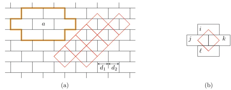
9.2 (a) The plane is tessellated with congruent rectangles to form the
common brick wall pattern, where d1 =d2. Each of the red rhombi
represents the lattice unit of the pattern. In the assembled structure
of robots, each robot has the potential of having six adjacent robots
in its one-hop neighborhood (imagine a robot occupying the site a
and its potential six neighbors inside the orange polygon). (b) Each
of the lattice units involves four rectangular areas, denoted as i, j,
9.3 (a) A target structure. Each rectangle represents a site, to be
occu-pied by a robot. (b) GraphC represents the mechanical connectivity
of the finally assembled structure. (c) The faces of C, f1 and f2
(except for the smallest faces), are free from narrow corridors. . . . 83
9.4 (a), (b) The gap between robots a and b can essentially block the
incoming robot. (c) The gap between a and b can affect assembly
that happens at a distance spatially. (d) If we want robots to occupy
the seven open sites, at least the last robot has to pass through a
gap just as large as its side. . . 85
10.1 A target structure T, which can be represented as a sequence of the
coordinates of the centroids (shown as the black dots) of the member
sites, with respect to the xy-frame that is oriented as the grid of the
lattice units (Figure 9.2). Although the order of the sequence does
not matter, the site numbers are labeled to help explain the progress
of the algorithm. . . 88
10.2 (a) The target structure shown in Figure 10.1 has been decomposed
into the cells in the left panel. The right panel showsC0, representing
the mechanical connectivity among the cells. (b) The seeds of the
cells are colored red, green, or blue. C0 can be turned into a tree
10.3 (a) GA returned by Algorithm 3. (b) The same graph as (a), but
topologically sorted. The sites grouped in each dotted boundary can
be occupied simultaneously once the preceding groups are occupied. 92
10.4 Some possible snapshots when we assemble the example shape
ac-cording to GA shown in Figure 10.3. Each panel shows the most
populated structure that can be obtained without having s
occu-pied. s can be accessed by an incoming robot through the empty
space at least as wide as two rows of sites. . . 96
11.1 A target structure T, which can be represented as a sequence of the
coordinates of the centroids (shown as the black dots) of the member
sites, with respect to the xy-frame that is oriented as the grid of the
lattice units (Figure 9.2). . . 100
11.2 C, the graph representing the mechanical connectivity ofT, and ∂C,
the subgraph of C that is the frontier of the outer face. . . 102
11.3 Since∂C has a vertex of degree 1,s, the vertex is to be disassembled.
11.4 (a) ∂C currently has two blocks that are cycles, denoted as B1 and
B2. Each red vertex is a cutvertex of ∂C that belongs to B1 or B2.
(b), (c) Suppose that we picked B1. si, sj, and sk can potentially
be disassembled from the structure; C will then be updated as the
graph shown below. In case we picked B2, (d) si can potentially be
disassembled from the structure; (e) because sk is the cutvertex, the
sequence hsi, sj, ski will not be returned. . . 104
11.5 Each panel is zooming in on some part of C shown in Figure 11.2
along with the rhombus, as appeared in Figure 9.3c, translating along
the frontier of ∂C; the centroid of the rhombus follows the dotted
lines. The panels (a), (b), and (c) show what happens to the path of
the rhombus after sites are removed from C according to Algorithm 4. 108
12.1 (a) The right panel shows a target structure composed of 207 member
sites, which looks like the continental United States. Choosing the
red site as the seed can minimize the assembly time by maximizing
parallelism. (b) Six snapshots showing how the given seed grows into
the target structure. In each panel, the gray sites are to be occupied
12.2 (a) The right panel shows a target structure composed of 435 member
sites, which looks like the harbor on the left panel. Choosing the
red site as the seed can minimize the assembly time by maximizing
parallelism. (b) Six snapshots showing how the given seed grows into
the target structure. In each panel, the gray sites are to be occupied
in the next snapshot around the current structure colored black. . . 113
12.3 The Assembly Planner computed the optimal assembly plans for the
structures, starting from the seeds colored red. The minimum heights
of (a) and (b) were 3 and 4, respectively. . . 115
12.4 Assembling congruent lego blocks into the four letters with holes, ‘R’,
‘O’, ‘B’, and ‘O’. . . 116
12.5 Structures autonomously constructed with our robotic boats that are
0.5m in length. (a) A landing platform for an aerial vehicle. (b) A
bridge for a ground vehicle. (c) For the bridge, we had the Assembly
Planner compute a plan starting from one end (the site colored red).
The snapshots show how the bridge grows. . . 117
13.1 Six symmetric patterns that can be generated by congruent
13.2 A target structure of type cmm with the graph C (in the center)
and the equivalent ones of other types in the sense of geometric
adja-cency/mechanical connectivity. Also shown in the block arrows are
modes of docking between two robots sufficient to assemble the
struc-tures (symmetric cases are omitted); then, the strucstruc-tures of types
cmm, p2, pmg, pgg, and pmm have the same mechanical
con-nectivity represented as C. The structure of type p4g is composed
of the meta modules, each of which is composed of two rectangles. . 120
13.3 Corridors as wide as two contiguous cells are navigable for all the
patterns: (a) cmm, (b) p2, (c) pmg, (d) pgg, and (e) pmm. It
can be seen that the robot, colored black, can navigate the corridors
at least by omnidirectional translation. . . 122
13.4 Disassembling si, sj, and sk one at a time in the order enumerated
guarantees easy accessibility (a robot does not have to pass through
a gap as wide as its side) for not only (a) type cmm but also (b)
Part I
Chapter 1
Introduction
The early 1960s saw Unimate, the first industrial robot created by George Devol,
working on an automobile assembly line. Since this installation of Unimate, a wide
variety of robot technologies have been developed to perform various manipulation
tasks that can help or completely replace humans in environments ranging from
a manufacturing plant to outer space or the bottom of the sea. For example, a
robot played an important role in capturing the Boston Marathon bombing suspect
in 2013 by helping law enforcement authorities remove the tarpaulin of the boat.
The DARPA Robotics Challenge1 reflects growing interest in developing robots that
can physically assist humans with challenging manipulation tasks, particularly for
responding disasters.
The work presented in this thesis contributes to two of the most fundamental
problems in robotic manipulation: robotic grasping and assembly. The capability
to grasp or assemble objects can provide a sufficient functional basis for a wide
variety of tasks which robots can contribute to, for example, manufacturing, disaster
response, space exploration, assisted living, and medical operation.
The two problems are closely related to each other. According to Mason (2001),
grasping an object is a kind of assembly if we consider assembly as a fundamental
process employed in manipulation tasks; assembly is an application task that builds
on a wide range of subtasks including grasping. In the literature, the problems
are indeed sharing many common issues; for example, contact analysis has been
important in both problems.
Our approach to robotic grasping and assembly takes account of modular robot
systems. For grasping, we consider a modular manipulator whose arms are
recon-figurable by attaching or detaching modular links and end-effectors as needed. For
assembly, we consider modular units with identical geometry that can collectively
be assembled into various target structures. The theories and algorithms we present
here are suitable for the modular frameworks. In fact, the tasks of grasping and
assembly can benefit from such modular systems. For example, the modular
manip-ulator can easily adapt to the sizes and shapes of various objects; the parallelism
of the multiple modular building blocks makes the system robust to failures. In
addition, mass production of standardized modules can make individual modules
Section 1.1 formally defines our research problems. Section 1.2 enumerates the
contributions of the thesis. Section 1.3 describes our research vision based on the
thesis. Section 1.4 gives an outline of the thesis.
1.1
Problem Statement
This thesis addresses two central problems in robotic manipulation.
First, we are concerned with developing a theoretical framework for robotic
grasping using effectors (or “fingers”) with curved contact surfaces; we also present
one application of the idea to a scenario of grasping objects with a modular robot
system. Effectors with appropriate curvature properties can be effective for
re-straining the mobility of an object. For example, consider the two grasps shown in
Figures 1.1a and 1.1b, each of which has one point and one planar contact; the grasp
of Figure 1.1b is more restrictive in that the object cannot actually escape from the
effectors due to the concavity of the effector contacting the vertex. Figure 1.1c
illustrates a grasp by a modular manipulator equipped with two end-effectors with
curved contact surfaces.
Most practical solutions in robotic grasping involve specially-designed hardware
and control algorithms that are tailored only to a couple of objects to be handled
or grasped. A robot system that can grasp a wide variety of object shapes without
many different types of effectors or complex multi-fingered hands can save time
(a) (b) (c)
Figure 1.1: The tetrahedron is grasped by (a) the two planar effectors, (b) the planar and concave effectors, and (c) the modular manipulator.
clearing rubble in an unstructured environment. In addition, it is imperative to
develop planning algorithms that can guarantee the stability of the process of grasp
acquisition and robustness to sensing/positioning errors.
Second, we address the development of planning algorithms for assembling
ar-bitrary planar target structures with congruent, rectangular building blocks, which
can be applied to constructing floating structures on water with modular, robotic
boats. Figure 1.2 illustrates the scenario we are concerned with: in Figure 1.2a,
the rectangular mobile units are being assembled into the growing structure, which
locally looks like the common brick wall (Figure 1.2b), in a parallel manner.
Fig-ure 1.2c shows an example target structFig-ure assembled with physical robots.
We seek to create efficient algorithms guaranteeing complete, correct assembly
and supporting parallel execution, mimicking the process seen in human workers
collaboratively constructing a brick wall. Prior works on assembly planning (see
Sec-tion 2.2) discussed automated geometric reasoning based only on local informaSec-tion.
(a) (b) (c)
Figure 1.2: (a) Robots, depicted as solid, black rectangles, are being assembled into the planar structure, which locally looks like the common brick wall shown in (b). (c) A landing platform autonomously assembled with robotic boats.
example, parts may have to pass through narrow corridors on the way to their
tar-get positions, which may necessitate difficult maneuvers. Decentralized approaches
to robotic self-assembly (see Section 2.3) presented planning algorithms that scale
well; however, it can be hard to guarantee completeness with such algorithms.
1.2
Thesis Contributions
The main contributions of this thesis fall into two distinct areas.
First, we present a novel theory of three types of immobilizing grasps and cages
that can effectively restrain the mobility of any object modeled as a polyhedron. The
grasps and cages are formed by at most three effectors with appropriate geometry,
which can simply be a planar, cylindrical, or spherical surface. We apply the theory
to implement hardware and software for stable object grasping with a modular
robot system, which can adapt to the sizes and shapes of a wide variety of objects.
Our work is based on a conservative assumption that two bodies in contact can only
contact. The conservativeness can be seen clearly if we consider how the octopus
firmly grasps a prey by virtue of the frictional, soft, bilateral contacts made by the
tentacles. The conservativeness will allow us to apply our approach to a wide range
of scenarios without such capable hardware like the tentacles of the octopus.
Second, we present two novel planning algorithms that can be applied to
con-structing planar structures with congruent, rectangular mobile robots, which
col-lectively form the brick wall pattern. The algorithms can address arbitrary target
structures2; moreover, target structures without internal holes can be assembled
in a parallel manner. It takes O(m) time to run the algorithms where m is the
number of the modular units constituting the structure. Following the resultant
assembly plan guarantees easy accessibility: each robot is guaranteed a path with
a finite clearance between itself and the growing structure. We also show that the
algorithms can be extended to assemble structures of other symmetric patterns that
can be formed with congruent rectangles.
1.3
Vision
In order to illustrate the applications of the ideas in this thesis, we present two
vignettes.
Vignette 1: Modular robot system for disaster response A team of
au-tonomous boats sails for an island that has just been struck by an earthquake and
the resultant tsunami. After anchoring off the coast of the island, some of the boats
unload a swarm of small modular robots. While the boats form an emergency
land-ing strip on the water, the robots assemble themselves into a team of spider-like
robots, which can move around the island cluttered with rubble. The multi-limbed
robots remove obstacles, search for survivors, and build temporary ground shelter
with bricks scattered over the ground.
Vignette 2: Modular robot system for space exploration Another group
of the same modular robots deployed from a lunar lander forms a three-armed
torso that is to be mounted on a rover. The three-armed rover performs sample
acquisition and coring with two of the arms immobilizing a rock sample and the
remaining one operating a tool.
The vignettes may sound far-fetched, but this thesis can be the first step toward
the vision; in Chapter 14, we propose possible 5-, 10-, and 15-year milestones that
can be reached by extending the ideas described in this thesis.
In addition, we also envision industrial applications. For example,material
han-dlingis defined as the movement, storage, control and protection of materials, goods
and disposal3. According to the U.S. Roadmap for Material Handling & Logistics4
published in January, 2014, all that movement and handling accounts for 8.5
per-cent of gross domestic product (at least $1.33 trillion) in the United States and
the total continues to grow at roughly 4 percent annually. Robotic grasping and
assembly, the topic of the thesis, provide a sufficient functional basis for automating
many tasks involved with material handling.
1.4
Organization of This Work
The thesis is organized as follows. In the following chapter, we review relevant
literature in the areas of robotic grasping, robotic assembly, and modular robotics.
Part II presents our work on robotic grasping with modular robots. This part
builds on our previous work presented in Seo et al. (2012), Seo and Kumar (2012),
Seo et al. (2013b). Chapter 3 introduces concepts and terminology necessary to
develop our theory and algorithms. Chapter 4 discusses three types of immobilizing
grasps using curved effectors that can be applied to a wide range of objects including
polyhedra. Chapter 5 discusses three types of cages derived from the immobilizing
grasps and explains how to establish sufficient conditions for caging. Chapter 6
presents an algorithm for synthesizing the immobilizing grasps and cages. Chapter 7
extends our theory by adding more types of grasps and cages. Chapter 8 discusses
3
http://www.mhi.org
the implementation of our approach on a modular robot system, with experiments.
Part III is concerned with developing assembly planning algorithms for
con-structing modular structures. This part builds on our previous work presented in
Seo et al. (2013a), O’Hara et al. (2014). Chapter 9 describes our approach to
design-ing the algorithms. Chapter 10 presents our first algorithm that supports parallel
assembly and discusses its correctness. Chapter 11 presents our second algorithm,
which can address target structures with internal holes, and discusses its
correct-ness. Chapter 12 discusses the implementation of the algorithms, with experiments.
Chapter 13 addresses how to extend the algorithms to more general patterns.
Chapter 2
Literature Review
This chapter outlines literature on robotic grasping, robotic assembly, and modular
robotics that is relevant to this thesis.
2.1
Robotic Grasping
Robotic grasping has been an active research area over the past few decades. We
here divide the prior work into two categories: one focusing on immobilizing objects
by making contacts (prehensile approach) and the other based on caging
(non-prehensile approach). For each approach, we introduce theoretical aspects and
examples of robotic systems. See Bicchi and Kumar (2000) for a more general
2.1.1
Prehensile Approach
We begin with discussing the closure properties of grasps. A grasp is defined as
force closed (Nguyen 1988) if and only if it can resist any external wrench. If a
grasp is force closed with frictionless contacts, it is said to be form closed
(Lak-shminarayana 1978) or immobilized (Rimon and Burdick 1998a). Trinkle (1992)
proposed a quantitative test formulated as a linear program for detecting form
closure. Markenscoff et al. (1990) showed that it is possible to immobilize a
three-dimensional object with seven frictionless point contacts, using first-order theories
based on contact normals. Algorithms for synthesizing force or form closed grasps
were presented by Ponce et al. (1997), Borst et al. (1999), Van der Stappen et al.
(1999). Rimon and Burdick (1998a,b) developed a second-order mobility theory
for rigid bodies in contact where the curvature properties at the contacts are taken
into account. Czyzowicz et al. (1991) showed that n+ 1 frictionless point contacts
suffice to immobilize a general n-dimensional polytope by using the effects of
rela-tive curvature; thus, for a three-dimensional object, four frictionless point contacts
suffice for immobilization.
It has been discovered that the stability of a grasp depends on the geometry
of the grasp, contact forces, and material properties. Mason and Salisbury (1985)
established a framework for testing the stability of a grasp: a grasp is stable if its
stiffness matrix is positive definite. Cutkosky and Kao (1989) showed that grasp
the fingers. Nguyen (1989) proved that all force closed grasps can be made stable.
Howard and Kumar (1996) established a framework for analyzing grasp stability
that takes compliance, contact forces, and the local curvature properties of the
bodies in contact into account. It was shown that immobilization implies dynamic
stability with elastic contacts (Rimon and Burdick 1998a,b).
In practice, having a large number of contacts can be beneficial to grasp
stabil-ity; however, synthesizing such a grasp can be computationally intractable. Pollard
(2004) presented an efficient algorithm for synthesizing many-contact grasps based
on user-provided examples. Similar approaches can also be seen in the literature on
whole-body grasping (Hsiao and Lozano-Perez 2006) and enveloping grasping
(Trin-kle et al. 1988). Napier (1956) showed that there are two approaches to achieving
stability in human grasping: power grip and precision grip. Whole-body grasps and
enveloping grasps are in the same vein of the human power grip, where an object
is held by a large number of contacts between the flexed fingers and the palm.
Since Hanafusa et al. (1977) presented one of the earliest examples of robotic
hands, various robotic hands have been developed. Our work is relevant with the
approach to building simple yet versatile end-effectors that can be seen in Jacobsen
et al. (1986), Ulrich et al. (1988), Dollar and Howe (2010), Kragten et al. (2011),
Mason et al. (2012). Another relevant approach can also be seen in the literature
on modular fixturing (Brost and Goldberg 1996, Ponce 1996). Recently, there has
ob-jects with some autonomy. Saxena et al. (2008) presented a vision-based approach
to robotic grasping and demonstrated real systems that can grasp previously
un-known objects using two-dimensional images; similar approaches can be seen in
Morales et al. (2002), Bowers and Lumia (2003). Hudson et al. (2012) developed
an autonomy system that can perform dexterous, high-precision tasks such as key
insertion.
2.1.2
Non-Prehensile Approach
In contrast to the prehensile approach, the literature on caging investigates how
to arrange “obstacles” (that is, robotic fingers or effectors) around an object so
as to bound its mobility without necessarily making contact. Caging allows us
to sidestep some difficult issues such as modeling contacts or optimizing contact
forces although the caged object may have some freedom to move. Rimon and
Blake (1999) formulated a technique for computing cages of two-fingered hands;
Davidson and Blake (1998a) extended the result to three-fingered hands. Vahedi
and van der Stappen (2008a,b,c, 2009) provided an algorithm for synthesizing cages
of two and three fingers around polygonal objects and formalized the concepts of
squeezing and stretching cages for polygonal objects, which were generalized by
Rodriguez and Mason (2009) to address objects in Euclidean spaces of arbitrary
dimension. Allen et al. (2012) presented a simpler algorithm for computing
proposed a solution to synthesizing three-finger cages on the plane where two of the
fingers are fixed. Other interesting approaches include Zamfirescu (1995), Maehara
(2011), Fruchard (2012) where they investigated how to cage objects with just a
single circle. Rodriguez et al. (2012) discussed the relationship between caging and
grasping: they investigated when a cage can be a useful waypoint to an equilibrium
grasp.
Recently, there have been efforts to take advantage of caging to robustify robotic
tasks. Davidson and Blake (1998b) presented error-tolerant, vision-based planar
grasping by closing fingers that form a cage. Gopalakrishnan and Goldberg (2002)
presented a simple gripper with two vertical, parallel cylindrical jaws that can
sta-bly grasp objects by forming a cage on concavities. Diankov et al. (2008) proposed
a motion planning algorithm for performing manipulation tasks with cages,
relax-ing task constraints. Yokoi et al. (2009) presented an approach to transportrelax-ing
objects using cages formed by not only robots but also the environment such as
walls. Cappelleri et al. (2011a,b) employed cages formed by micro-manipulators
for transporting and manipulating micro-scale polygonal parts. Dogar and
Srini-vasa (2011) showed that simple manipulation such as quasi-static pushing can help
robots stably cage and grasp objects even in clutter. There is a body of literature
2.2
Assembly Planning
Robotic assembly is a broad topic that is involved with a wide variety of issues
in manipulating objects, which include grasping, caging, fixturing, pushing, and
part orienting. See Mason (2001) for a general introduction. We here focus on
the literature on assembly planning. According to Halperin et al. (2000), assembly
planning is defined as the problem of finding and sequencing the motions that
put the initially separated parts of an assembly together to form the assembled
product. Lozano-Perez (1976) is one of the earliest works that focus on specific
issues in planning mechanical assembly. The problem is generally approached by
considering how to establish a disassembly plan from a final product.
2.2.1
Assembly Sequencing
Assembly sequencing is a variant of assembly planning that received early
atten-tion. In assembly sequencing, the parts of an assembly are often assumed to be
free-flying, sidestepping issues such as how to physically perform assembly
oper-ations and focusing on the geometric constraints imposed by the product itself.
However, Assembly sequencing is a hard problem; Natarajan (1988), Kavraki and
Kolountzakis (1995) discuss the PSPACE-hardness or NP-completeness of instances
of assembly sequencing. De Fazio and Whitney (1987) presented a method for
generating all valid assembly sequences based on a user input on the geometric
hypergraph representation of assembly plans that combines all feasible assembly
sequences for a given product; the representation enables the selection of the best
assembly plan and parallel execution of assembly operations. Ko and Lee (1987),
Arkin et al. (1989), Wilson and Rit (1990) also presented similar approaches.
Wil-son and Latombe (1994) presented the notion of a non-directional blocking graph,
representing the geometric interferences among the parts in an assembly, which
allows assembly sequences to be computed in polynomial time.
2.2.2
Beyond Traditional Assembly Sequencing
The traditional approach to assembly sequencing has been generalized in many
directions. Latombe et al. (1997), Thomas et al. (2003), Ostrovsky-Berman and
Joskowicz (2006) investigated assembly planning for toleranced parts. Halperin
et al. (2000) presented a general framework for assembly planning that can address
additional constraints such as toleranced parts, stability, and tool use. Romney
(1997) presented a method to concurrently generate an assembly sequence and
de-sign a fixture to hold intermediate subassemblies. Mosemann et al. (1998), Rakshit
and Akella (2014) presented assembly/disassembly sequencing that takes part
sta-bility into account in the presence of external forces such as gravity and friction.
Assembly planning can also be understood as a variant of robot motion planning
where the goal is to assemble robotic parts into one coherent structure (LaValle
based on sampling-based robot motion planning. Similar approaches can also be
seen in Ferre and Laumond (2004), Le et al. (2009).
2.3
Modular Approach to Robotic Tasks
According to Yim et al. (2009), modular (self-reconfigurable) robots are robots
composed of a large number of repeated modules that can rearrange their
connect-edness to form a large variety of structures. Modular robots promise to be versatile,
robust, and cost-efficient (Yim et al. 2009), but the advantages may compromise
performance as observed by Yim et al. (2007b). We here review the applications of
modular robotics to self-assembly, locomotion, and manipulation tasks.
2.3.1
Self-Assembly
There is extensive literature on modular self-assembly; here the focus is on
generat-ing a wide range of structures with possibly congruent modules arranged in a
two-or three-dimensional grid structure. Murata et al. (1994) presented a mechanical
system composed of repeated modular units and a decentralized software system
for self-assembly. Kotay et al. (1998) proposed Molecule, a robotic module that
can self-reconfigure, along with an efficient motion planning algorithm. Yim et al.
(2001) defined a class of metamorphic robotic system capable of approximating any
three-dimensional shapes and presented distributed control algorithms for
general model of self-reconfigurable robots, with applications to real systems. There
is a body of literature addressing cube style modular systems with a wide variety
of modes of locomotion between voxels (pixels); examples include Hosokawa et al.
(1998), Kurokawa et al. (1998), Rus and Vona (2001), Vassilvitskii et al. (2002),
Gilpin et al. (2008), Romanishin et al. (2013).
Difficulties in fabricating small modules with onboard sensing, computation, and
actuation often result in outsourcing some functions. White et al. (2004) proposed
a self-reconfigurable robotic system where simple modules, without moving parts,
exploit Brownian motion in their environment for locomotion. Bishop et al. (2005)
introduced a self-organizing modular robotic system where each module floats
pas-sively on an air table and docks to others upon random collisions. Werfel and Nagpal
(2008) presented a decentralized algorithm for constructing three-dimensional
tar-get structures with a bipartite system comprising passive, cubic blocks and mobile
robots that move the blocks. White et al. (2009) presented a chain of
tetrahedron-shaped modules that can be folded into three-dimensional target shapes by an
ex-ternal actuator. Petersen et al. (2011) presented a bipartite system for constructing
walls, composed of mobile robots and passive building blocks that can be
2.3.2
Locomotion
Modular robots have showed their versatility in locomotion. Yim (1994) presented
statically stable locomotion gaits with his modular robot system, Polypod. Yim
et al. (2000) presented PolyBot, a modular robot system that can locomote over a
variety of terrain and switch between two locomotion modes by self-reconfiguration.
Yim et al. (2007a) implemented a simple robotic system that can recover after
disassembly from high-energy events. Sastra et al. (2009) implemented dynamic
rolling, which was proven to be a fast and energy-efficient way of locomotion, with
a modular robot system, CKbot. Burdick et al. (1994), Sfakiotakis and Tsakiris
(2007), Lipkin et al. (2007), Hatton and Choset (2010) investigated gait generation
for modular hyper-redundant (snake-like) robots.
2.3.3
Manipulation
The literature on multi-robot manipulation provides techniques for handling objects
in a cooperative manner. When multiple robots manipulate a common object, it is
necessary to control both the motion of the object and the internal forces exerted
on the object (Murray et al. 1994). In addition, the dynamics of such systems is
typically subject to unilateral constraints: the robots can only push or pull (for
example, by cable tension) the object. Murray (1996), Sugar and Kumar (1999),
Cheng et al. (2009), Fink et al. (2011), Bernard et al. (2011), Sreenath and Kumar
trans-port. A group of literature shows that robotic object handling can be facilitated by
caging with a team of multiple robots: Kosuge et al. (1999), Pereira et al. (2004),
Montemayor and Wen (2005), Fink et al. (2008) presented approaches to
develop-ing decentralized control algorithms. Some literature on cooperative transport took
inspiration from the behaviors of social insect colonies (Kube and Bonabeau 2000,
Part II
Chapter 3
Preliminaries: Caging and
Grasping
This chapter introduces concepts and terminology relating caging and grasping that
we use in developing our theory and algorithms.
3.1
Caging
Acage around an object bounds its mobility (Figure 3.1a): the caged object cannot
be moved arbitrarily far from its original position without penetrating the
surround-ing effectors formsurround-ing the cage. Equivalently, a cage can also be defined in terms
of the mobility of the surrounding effectors by regarding the object as an obstacle:
according to Rodriguez et al. (2012), a cage is a configuration of effectors that lies
of the effectors (note that the system is assumed to move as a single rigid body).
Rodriguez et al. (2012) formalized the concept of an F-cage, which is generally
stricter than that of a cage. Let F be a scalar function defined on effector
config-urations. Then an F-cage is a configuration of the effectors that cages an object
even if they have freedom to move while maintaining the value of F. An F-cage is
anF-squeezing(stretching) cage if it still cages the object even if the effectors have
freedom to move while decreasing (increasing) the value of F.
(a) (b) (c)
Figure 3.1: (a) Caging the triangle with the three point effectors. (b) Immobilizing the regular triangle with the three point effectors located at the center of each edge. (c) Clamping the tetrahedron with the two planar effectors contacting the vertex-face pair. The red arrows are involved unit contact wrenches under the assumption of frictionless, rigid, unilateral contact in (b), (c), and all upcoming figures.
3.2
Contact
We are mainly concerned with an object modeled as a polyhedron in contact with
effector surfaces. There can then be three types of contact geometry: point,line, and
planar contact (Mason and Salisbury 1985, Mason 2001). For example, Figure 3.1c
shows one point and one planar contact between the two planar effectors and the
contact force/moment pair, given by the positive linear combinations ofunit contact
wrenches that are normalized, linearly independent vectors that span the vector
space of the contact wrenches (see Figures 3.1b and 3.1c). Our work is based on an
assumption that all contacts are frictionless, rigid, unilateral (unilateral contacts
can only push an object); then, the unit contact wrenches are the vectors of the
normalized screw coordinates only of the inward-pointing contact normals (Mason
2001). If we assume frictional, soft, bilateral contacts, more types of unit contact
wrenches should be considered (Murray et al. 1994); this shows the conservativeness
of the assumption.
P Q
R
Figure 3.2: The plane is contacting the virtual edge P Q between the two “real”
vertices P and Q.
A line contact can be made on avirtual edge(Peshkin and Sanderson 1986) that
is composed only of the vertices delimiting the edge without the interior (Figure 3.2).
It can be seen that a “real” edge and a virtual edge are indistinguishable in terms
of their ability to produce contact wrenches, under the assumption of frictionless,
rigid, unilateral contact, if we are given a sufficiently large effector surface that can
is, two. Similarly, a planar contact can also be made on a virtual face.
3.3
Grasping
To grasp an object is to restrain its mobility by making contacts with effectors.
A grasp can be in equilibrium if the net contact wrench, the sum of all contact
wrenches, can be made zero in such a way that not all contact wrenches are equal
to zero (Rimon and Burdick 1998a). If there is no object twist, linear/angular
velocity pair (Murray et al. 1994), consistent with the contacts of an equilibrium
grasp, the object is said to be immobilized to the first order (Rimon and Burdick
1998a) (or form-closed (Mason 2001)), that is, the configuration of the object is an
isolated point in the free space. Even if such a twist exists, any finite motion may
be restricted by considering surface curvature effects. For example, in Figure 3.1b,
the object may instantaneously rotate about its centroid (so a first-order kinematic
analysis does not predict immobility), but any finite rotation results in penetrating
the effectors. This idea is formalized using the concept of second-order immobility
(Rimon and Burdick 1998a,b). Seven (four) point effectors are required to
immobi-lize a polyhedral object to the first (second) order with frictionless, rigid, unilateral
contacts (Markenscoff et al. 1990, Czyzowicz et al. 1991). Such immobility
con-ditions are purely geometric; information on contact geometry is thus sufficient to
investigate first- or second-order immobility. An equilibrium grasp is called a
necessarily an immobilizing grasp.
3.4
Clamping
Clamping(Bose et al. 1996), also known asparallel-jaw grasping, is one way to realize
equilibrium grasps by holding an object between two parallel planar “jaws.” An
object that is clamped can only move on the plane of the jaws, without penetrating
them. If the jaws can exert frictional forces, the grasp can be force closed: an
arbitrary contact wrench can be applied. Consider the antipodal pair of a convex
polyhedral object, which is the intersection of the object with a pair of parallel
support planes; an antipodal pair can thus be a vertex, edge,
vertex-face, edge-edge, edge-vertex-face, or face-face pair. According to Bose et al. (1996), all
convex polyhedra can be clamped with parallel-jaw grippers. The grippers are then
on one of the last four types of antipodal pairs, that is, vertex-face, edge,
edge-face, or face-face; such an element pair can determine the width of a polyhedron,
the minimum distance between two parallel supporting planes. Figure 3.1c shows
Chapter 4
Immobilizing Objects with Curved
Effectors
In this chapter, we discuss how to immobilize a three-dimensional object using at
most three contacts, each of which can be a point, line, or planar contact made
with a curved effector that can be represented as a two-dimensional manifold with
boundary. In Sections 4.1, 4.2, and 4.3, we present three types of immobilizing
grasps that can be applied to objects modeled as polyhedra; we also discuss the
geometry of effectors that can realize the grasps. In Section 4.4, we show that any
polyhedron can be immobilized by the grasps and discuss how the assumption of
4.1
Immobilizing with Three Point Contacts
In this section, we show that it is possible to immobilize a polyhedron with three
point contacts. We begin with choosing three vertices where the contacts can be
made. See Figure 4.1a. Let P andQbe two vertices of the given polyhedron where
two point contacts can be made with a pair of parallel planes perpendicular to P Q;
the inward-pointing (toward the interior of the polyhedron) contact normals at P
and Qpoint toward each other. LetR be a vertex, not onξ(the line ofP Q), where
a point contact can be made with a plane such that the ray of the inward-pointing
contact normal intersects ξ.
(a) P Q R ξ (b) P Q R ξ (c) P Q R ξ (d) P Q R ξ
Figure 4.1: (a) (P, Q, R) is a vertex-vertex-vertex triple where three point contacts
immobilizing the octahedron can be made. (b) The front view of the octahedron
with the two curved effectors contacting P and Q. The effectors can locally be
embedded inside the ball whose diameter has endpoins P and Q, except for the
points contacting P and Q. (c) An immobilizing grasp by the effectors with a
spherical surface. (d) An immobilizing grasp by the cone-shaped effectors.
Three point contacts on P, Q, and R made by curved effectors can immobilize
the polyhedron if (1) a neighborhood of the effector surface around the point
con-tacting P (Q), except for the point itself, can be embedded inside the ball whose
surface around the point contacting R, except for the point itself, can be embedded
inside the cylinder of radius d(R, ξ) with axisξ, where d(R, ξ) denotes the shortest
distance betweenRandξ. If condition (1) is satisfied, as can be seen in Figure 4.1b,
the polyhedron cannot move at all except for rotating about ξ because P Q is at a
configuration that is isolated in the free space: any finite displacement ofP Qresults
in penetrating the effectors atP orQ. Furthermore, if condition (2) is satisfied, the
polyhedron cannot rotate about ξ because the rotation results in penetrating the
effector at R. Two example grasps are shown in Figures 4.1c and 4.1d: effectors
with a spherical surface of a sufficiently small radius (Figure 4.1c) or effectors with
a cusp (Figure 4.1d) can satisfy the two conditions.
4.2
Immobilizing with a Point, a Line, and a
Pla-nar contact
We here show that it is possible to immobilize a polyhedron with one point, one
line, and one planar contact. We begin with choosing a vertex, an edge, and a face
where the contacts can be made. See Figure 4.2a. At P and QRST, a point
and a planar contact can be made with a pair of parallel planes. The ray of the
inward-pointing contact normal at the vertex intersects the interior of the face; the
inward-pointing contact normals at the face point toward the vertex. Among the
that is, P S. (a) P Q R S T ξ (b) P P0 ξ (c) P Q R S T ξ (d) P Q R S T ξ
Figure 4.2: (a) (P, P S,QRST) is a vertex-edge-face triple where a point, a line,
and a planar contact immobilizing the pyramid can be made. (b) The front view of the object with the two effectors contacting the vertex and the face. The curved
effector contacting the vertex, P, can locally be embedded inside the space between
the two supporting planes, except for the point contacting P. (c) An immobilizing
grasp by the effectors with a spherical, a cylindrical, and a planar surface. (d) An immobilizing grasp where the point (line) contact is made by the cone-shaped (V-shaped) effector.
Three (one point, one line, and one planar) contacts on the vertex (P), edge
(P S), and face (QRST) by curved effectors can immobilize the polyhedron if (1)
the contact area of the planar contact contains a neighborhood of P0, the foot of
perpendicular from P to the face (Figure 4.2b), (2) a neighborhood of the effector
surface around the point contacting P, except for the point itself, can be embedded
inside the half-space below (toward the interior of the polyhedron) the plane
con-tacting P (Figure 4.2b), and (3) a neighborhood of the effector surface around the
line segment contacting P S, except for the line segment itself, can be embedded
inside the cone formed by rotating P S about ξ (the line of P P0). If conditions (1)
and (2) are satisfied, as can be seen in Figure 4.2b, the polyhedron cannot move at
(3) is satisfied, the polyhedron cannot rotate about ξ because the rotation results
in penetrating the effector at P S. Two example grasps are shown in Figures 4.2c
and 4.2d.
4.3
Immobilizing with Two Line Contacts
We here show that it is possible to immobilize a polyhedron with two line contacts.
We begin with choosing two edges where the contacts can be made. See Figure 4.3a.
P Q and RS are two skew edges of the given polyhedron where two line contacts
can be made with a pair of parallel planes that are perpendicular to ξ, the common
perpendicular of the edges. ξand the two edges intersect in the interior of the edges.
The inward-pointing contact normals at one edge point toward the other edge.
(a) P Q R S ξ (b) P R S ξ (c) P Q R S ξ (d) P Q R S ξ
Figure 4.3: (a) (P Q, RS) is an edge-edge pair where two line contacts immobilizing
the tetrahedron can be made. (b) The front view of the object with the two curved effectors contacting the edges. The curved effectors can locally be embedded inside the space between the two supporting planes (except for the line segments contacting the object). (c) An immobilizing grasp by the effectors with a cylindrical surface. (d) An immobilizing grasp by the two V-shaped effectors.
Two line contacts on the edges by curved effectors can immobilize the polyhedron
(RS), except for the line segment itself, can be embedded in the half-space below
(above) the plane contacting it (Figure 4.3b). Note that the two contact areas (the
line segments) and ξshould intersect. If the condition is satisfied, as can be seen in
Figure 4.3b, the effectors are not only clamping the polyhedron but also restricting
any planar motion: one of the effectors only allows the object to translate along
the line of its contact, but such motion is not allowed by the other effector. Two
example grasps are shown in Figures 4.3c and 4.3d.
4.4
Analysis
This section presents an analysis showing that the three types of grasps discussed
in Sections 4.1, 4.2, and 4.3 are complete: every polyhedron can be immobilized by
applying at least one of the grasps. We break the analysis into two theorems.
First, we show that the grasp of three point contacts discussed in Section 4.1
suffices to immobilize all polyhedra.
Theorem 1. Every polyhedron can be immobilized by three frictionless, rigid,
uni-lateral point contacts made by appropriately concave effectors.
Proof. Every polyhedron has a vertex-vertex pair (P, Q) that admits two parallel
supporting planes perpendicular to P Qand contacting only P and Q, respectively,
in such a way that the interior of the polyhedron is between the planes. Consider
determining the maximum distance between two vertices of the collection.
Con-sider two planes ΠP and ΠQ perpendicular to P Q and contacting the polyhedron
respectively at P and Q. No other vertex of the polyhedron can be located on ΠP
and ΠQ because (P, Q) determines the maximum distance: ΠP (ΠQ) is supporting
the polyhedron only at P (Q). Therefore, (P, Q) is a desired vertex pair.
Next, we can find an additional vertex, not onξ (the line ofP Q), which admits
a supporting plane whose inward-pointing normal at the vertex directly points to
ξ. Consider one vertex that is the most distant from ξ and denote the vertex as
R; let ξ0 be a line parallel to ξ and passing through R. If R is the only vertex of
the polyhedron on ξ0, R must be a pointed vertex that admits a supporting plane
whose inward-pointing normal at R directly points toward ξ. R is then the desired
vertex. In case there are multiple vertices lying on ξ0, first choose a point on ξ0 as
its origin, then pick the vertex that is the most distant from the origin, and denote
the vertex as R. It can be seen that R is the desired vertex.
We finally get immobility with three appropriately concave effectors respectively
contacting P, Q, and R as explained in Section 4.1. Note that P, Q, and R are
on the convex hull of the polyhedron; otherwise, P and Q do not determine the
maximum distance and R is not the most distant from ξ, either.
We now show that other two types of grasps discussed in Sections 4.2 and 4.3
are also complete in the sense that every polyhedron whose vertices are in general
parallel, can be immobilized by at least one of those grasps.
Theorem 2. Every polyhedron whose vertices are in general position such that there
is no pair of either two planes or a line and a plane that are parallel, where each
line (plane) is determined by a distinct collection of two (three) vertices, can be
immobilized by either (1) one point, one line, and one planar contact or (2) two
line contacts made by appropriately concave effectors; the contacts are frictionless,
rigid, unilateral.
Proof. Consider the convex hull of the given polyhedron. Because the convex hull
does not have any pair of either two faces or an edge and a face that are parallel, it
can be clamped at one of its antipodal vertex-face or edge-edge pairs. The convex
hull (and thus the original polyhedron) can then be immobilized using the pair by
applying the grasp discussed in Section 4.2 or 4.3.
Note that the grasps employed in Theorem 2 might have contacts on virtual edges
or faces that are on the convex hull, but not belonging to the original polyhedron.
Remark : The three types of grasps can actually be applied to immobilizing a
wider range of objects in addition to polyhedra. Essentially, if there is a set of the
right contacts made with effectors having the right curvature properties, as discussed
in Sections 4.1, 4.2, and 4.3, then the object is immobilized. First, the place where
a point contact is made does not have to be actually pointed like a polyhedron
effectors to immobilize the object, it is only required that the actual geometry of
the object around P, Q, or R does not intersect the effector surface, whether the
actual geometry is smooth or pointed. Similarly, the place where a line (planar)
Chapter 5
Caging Objects with Curved
Effectors
Based on the three types of immobilizing grasps discussed in Chapter 4, it can be
seen that every polyhedron can be caged by two curved effectors.
Corollary 1. Every polyhedron can be caged by two appropriately concave effectors,
each of which is accommodating a single vertex, edge, or face.
Proof. According to Section 4.1, 4.2, or 4.3, it is possible to cage a polyhedron
with two curved effectors making contacts at a vertex-vertex, vertex-face, or
edge-edge pair. For example, Figure 5.1 shows three types of cages obtained by the
two effectors at the antipodal pairs in Figures 4.1c, 4.2c, and 4.3c, respectively.
(a) P Q (b) P Q R S T (c) P Q R S P0 Q
0
R0 S0
Figure 5.1: Cages of two curved effectors. The inscribed shapes colored red (the line segment in (a), the right circular cone in (b), and the tetrahedron in (c)) are used to establish sufficient conditions for caging in Section 5.1.
Although the effectors are contacting the objects in Figure 5.1, a cage does not
necessarily have to make contacts with the object. In order to see if an object is
caged, it is necessary to take overall effector geometry into account because it is
required to verify the compactness of the component of the free space to which the
configuration of the object belongs, which is a nonlocal property. For example, the
“depth” of a curved effector is critical in our discussion on caging here. In contrast,
recall that we need only local curvature properties in establishing the immobilizing
grasps in Chapter 4.
In this chapter, we address how to establish sufficient conditions for caging
three-dimensional objects in analytical (Section 5.1) and empirical (Section 5.2) manners.
In Section 5.3, we present a theoretical analysis on how to acquire stable grasps from