539 | P a g e
A VARIABLE REACTOR BASED INTEGRATED
POWER QUALITY CONTROLLER FOR MICROGRID
Sushma Gundu
1,
Rajesh Thota
2,
T.Venugopal
3ABSTRACT
A novel variable reactor based on magnetic flux control is proposed in this paper. The system configuration of
the novel variable reactor is presented, while its operational principle is analyzed. Based on the developed
variable reactor, a novel integrated power quality controller (IPQC) suitable for microgrid is proposed, which
can cater for the peculiar requirements of microgrid power quality, such as the harmonic high penetration,
frequent voltage fluctuation and overcurrent phenomenon, and bidirectional power flow and small capacity. For
the fundamental, the equivalent impedance of the primary winding is a variable reactor or capacitor. For the
nth-order harmonic, the equivalent impedance is very high impedance and acts as a “harmonic isolator.” The
system control strategy is also analyzed in detail. A set of three-phase IPQC has been constructed. The
simulation results verify the validity of the novel variable reactor and the IPQC.
Keywords
:- Microgrid, overcurrent, power quality, transformer, variable reactor.
I. INTRODUCTION
Distributed power generation has been emerged as a promising option to meet the growing customer needs for
electric power with an emphasis on reliability and environmentally friendly renewable energy. In this context, in
order to maximize the operational efficiency of the distributed energy resources (DERs) and take full advantage
of distributed power generation, as an effective means of integrating DERs into the traditional power grid,
microgrid is presented, which can enhance the local customer power supply reliability and system performance,
reduce the impact on large power grid, and minimize the system losses. Microgrid has good environmental and
economical benefits and has attracted more and more attentions of power researchers [1]-[6]. However, the
power quality problem of microgrid is much more serious than that of the traditional grid because of the
intermittency and randomness of DERs, the high penetration between conventional grid and microgrid, the
diversity of DERs, load, energy conversion unit, storage, and operating state. Microgrid power quality has the
following unique features compared with the conventional power grid [7].
1) Background harmonic of DERs and harmonic high penetration are more serious than those of the traditional
grid [17]. The traditional grid has less system background harmonic, and the harmonic is mainly from the
nonlinear load. However, in microgrid, in addition to the nonlinear load, DERs and energy storage converter
system access to microgrid may also generate harmonics.
2) Bidirectional power flow control is much more challenging [8]. Traditional distribution network is with the
540 | P a g e
3) Voltage fluctuation and sag often happen in microgrid [9]. In microgrid, except the voltage fluctuation andsags from the load change, most kinds of DERs, which are intermittent and random, will cause significant
voltage fluctuations in distribution network.
4) The overvoltage and overcurrent phenomena are more frequent [10]. In general, microgrid is comparatively
small in capacity, and the effect of load fluctuation on microgrid is more than that on the traditional power grid.
In addition to this, control mode switching of many converters connecting in parallel to bus bar and the seamless
state transition may produce overvoltage and overcurrent. So far, relevant research studies on microgrid power
quality controllers can be sorted into two types: unifunctional controllers and multifunctional controllers.
Unifunctional power quality controllers aim at a specific power quality issue in microgrid. Multifunctional
power quality controllers generally combine the power quality controller with the grid interfacing converter
through special control scheme [11], [12] or topology [13]. However, these multifunctional power quality
controllers do not take into account all of the aforementioned features of microgrid.
To date, there is less research on integrated power quality controller (IPQC) particularly suitable for microgrid
with the aforementioned features. In addition, the microgrid capacity is comparatively small, and it is not cost
effective to install various types of power quality controller. In order to solve these problems, a novel variable
reactor based on magnetic flux control is first proposed. In order to cater for the peculiar requirements of
microgrid of harmonic high penetration, frequent voltage fluctuation and overcurrent phenomenon, and
bidirectional power flow and small capacity, a novel IPQC suitable for microgrid is proposed based on the novel
variable reactor. The IPQC is characterized by mitigating the harmonic penetration, controlling the bidirectional
power flow, limiting the fault current and compensating the voltage fluctuation, and being a variable reactor.
Finally, simulation results are Provided to validate the analysis.
II. PRINCIPLE OF THE VARIABLE REACTOR
2.1. System Configuration
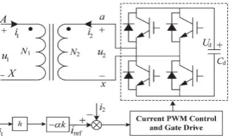
Fig. 1shows the single-phase system configuration of the novel variable reactor based on magnetic flux control.
Suppose that the turns of primary and secondary winding of the transformer are N1 and N2, respectively. The
turns ratio is represented by k = N1/N2. A transformer with air gap is selected, and its primary winding AX can be
connected in series or in parallel with power utility. The secondary winding ax is not connected with a normal
load but a voltage-sourced inverter. The voltages of the primary and secondary windings are u1 and u2,
respectively. The primary winding current i1 of the transformer is detected and functions as the reference signal
iref . h is the gain of the current sensor. Ud is the voltage of dc side of the inverter. Cd stands for the capacitance
of the dc capacitor. α is a controllable parameter, which will be explained later. The voltage-sourced inverter
and the current control are applied to yield a controlled current i2, which has the same frequency as i1. i2 is
541 | P a g e
Fig 1: System Configuration of the Novel Variable Reactor2.2. Equivalent T-Circuit of the Transformer
The magnetically coupled circuit of the transformer is central to the operation of the novel variable reactor,
which is shown in Fig. 2. The flow of currents in the two windings produces magneto motive forces (MMFs),
which, in turn, set up the fluxes.
Fig 2: Magnetically Coupled Circuit of the Transformer
The total flux linking each winding may be expressed as
Φ1 =Φl1 +Φm1 +Φm2 = Φl1 +Φ m (1)
Φ2 =Φl2 +Φm2 +Φm1 = Φl2 +Φ m. (2)
Herein, Φl1 and Φl2 are the leakage fluxes of the primary and secondary windings. Φm1 is the magnetizing flux
produced by the primary winding, and it links all turns of the primary and secondary windings. Φm2 is the
magnetizing flux produced by the secondary winding, and it links all turns of the primary and secondary
windings. Φmdenotes the resultant mutual flux.
The voltage equations of the transformer can be expressed as
u1 =r1i1 + dλ1/dt. (3)
u2 =r2i2 + dλ2/dt (4)
where r1 and r2 are the resistances of the primary and secondary windings, respectively. λ1 and λ2 are the flux
linkages related to the primary and secondary windings, respectively. If saturation is neglected and the system is
linear, the following equations can be achieved:
λ1 =Ll1i1 + Lm1(i1 +N2/N1i2) (5)
λ2 =Ll2i2 + Lm2(N1/N2i1 + i2) (6)
Herein, Ll1 and Ll2 are the leakage inductances of the primary and secondary windings, respectively. Lm1 and Lm2
are the magnetizing inductances of the primary and secondary windings, respectively. Lm1/N12 = Lm2/N22.when
the quantities of the secondary winding are referred to the primary winding, (3) and (4) become
u1 =r1i1 + Ll1di1/dt+ Lm1d/dt(i1 + i2 1
) (7)
542 | P a g e
Here, the prime denotes referred quantities of secondary winding to primary winding. Equations (7) and (8) canbe expressed as the following equations in phasor form:
U1 =r1I1 + jωLl1I1 + jωLm1 (I1 + I21) (9)
U21 =r21I21 + jωLl21I21 + jωLm1 (I1 + I21) (10)
The voltage equations in (9) and (10) with the common Lm1 suggest the equivalent T-circuit shown in Fig. 3 for
the two winding transformer.
Fig 3: Equivalent T-Circuit of the Transformer
Note that, in some equivalent T-circuit of the transformer, a core loss resistance rm, which accounts for the core
loss due to the resultant mutual flux, is connected in parallel or in series with the magnetizing inductance Lm1 (in
the later analysis, a series core loss resistance rm is taken into account in the equivalent T-circuit of the
transformer).
Let Z1 = r1 + jωLl1, which is the leakage impedance of the winding. Z21 = r21 + jωL1l2, which is the leakage
impedance of the secondary winding ax referred to the primary winding. Zm = rm + jωLm1, which is the
magnetizing impedance of the transformer. Here, ω is the fundamental angular frequency. Then, (9) and (10)
become
U1 =Z1I1 + Zm(I1 + I21) (11)
U21 =Z21I21 + Zm (I1 + I21) (12)
2.3. Principle of the Variable Reactor
In Fig. 1, the primary winding current is detected and functions as the reference signal, and the voltage-sourced
inverter is applied to track the reference signal to yield a controlled current i2.When controlled current i2
and the primary current i1 satisfy
I
2 1=
−αI
1(i.e.
, I
2=
−αkI
1)
.
(13)
Herein, α is a controllable parameter. The transformer is double side energized, and then, the following
equations can be obtained :
U1 =Z1I1 + (1 − α)ZmI1 (14)
U2
1
=Z2
1
I2 1
+ (1 − 1/α) ZmI2 1
. (15)
In terms of (14), from the terminals AX, the equivalent impedance of the transformer can be obtained, i.e.,
ZAX=U1/I1= Z1 + (1 − α) Zm. (16)
In terms of (16), the equivalent impedance of the primary winding of the transformer is a function of the
controllable parameter α. When α is adjusted, the primary winding exhibits consecutively adjustable impedance.
Equation (16) can be also achieved in terms of the resultant MMFs of the two windings acting around the same
path of the core. When a controlled current i2 produced by a voltage sourced inverter is injected into the
543 | P a g e
resultant flux set up by the MMF of the two windings is (1 − α) Φm. Then, the induced voltage produced by theresultant flux can be expressed in phasor form as
E1 = (1 − α) jωLmI. (17)
The primary voltage equation can be achieved as (14).In terms of (16), the relation between the equivalent
impedance of the primary winding and the parameter α is shown in Table I.
Table 1 : Equivalent Impedance of the Primary Winding of the Transformer
The variable reactor features hardly producing harmonics, simple control scenario, and with consecutive
adjustable impedance. Many flexible ac transmission systems (FACTS) devices can be implemented in terms of
the novel principle [38]. The variable reactor can be used in unified power flow controller to change the line
impedance between the sending and receiving ends to control the power flow; it can also substitute the
thyristor-controlled reactor of the thyristor-thyristor-controlled series capacitor; however, the proposed variable reactor does not
produce any harmonics; fault current limiter can be also implemented. In terms of the novel principle of the
variable reactor. Reactive power compensation can be all realized by the novel variable reactor. In addition, it
has been successfully applied the hybrid series active power filter based on fundamental magnetic flux
compensation.
2.4. DC-Link Voltage Control of the Variable Reactor
There must be some losses when the novel variable reactor system with inverter operates normally, and the
inverter will absorb active power to maintain the dc voltage constant. Fig.4 shows the dc-link voltage control
schematic of the variable reactor system. Herein, Ud∗and Ud represent the inverter dc reference and practical
voltage, respectively. An active current reference ip is added to the reference signal iref1 to achieve a new
reference signal iref2. A dc-link voltage PI controller is applied to make the inverter dc practical voltage Ud
follow the dc reference voltage Ud*. The output of the voltage PI controller is multiplied by the phase-locked
loop (PLL) output of u2 to yield the active current reference ip.
544 | P a g e
III. PRINCIPLE OF THE IPQC
3.1. System Configuration
The novel IPQC can be installed in series and parallel in microgrid or point of common coupling (PCC). For
simplicity, the IPQC is installed in PCC. Fig.5 shows the three-phase detailed system configuration of the IPQC
with transformer and inverter. Us and Ls represent the source voltage and impedance of conventional power
supply, respectively. The passive filters, which have the function of absorbing the harmonics, are shunted in
both sides. The primary winding of a transformer is inserted in series between the conventional power utility
and the micro grid, whereas the secondary winding is connected with a voltage-source PWM converter. Ud is the
voltage of the dc side of the inverter. The micro grid contains a harmonic load, a photovoltaic cell system, a
battery storage system, and a normal load. The proposed IPQC has the following functions.
Fig 5: Circuit of Proposed IPQC
3.2. Power Flow Control
When the power flow control and the fault current limiter are of concern, only the fundamental is taken into
account. In terms of the preceding analysis, the primary winding exhibits adjustable impedance Z1 + (1 − α) Zm.
With the change in coefficient α, the equivalent impedance of the primary winding can be achieved, which is
shown in Table I. Therefore, when the primary winding is connected in series in circuit, it can be applied to
control the power flow between the conventional power utility and the microgrid or the internal power flow of
the microgrid. The schematic of power flow control is shown in Fig. 6 when the novel variable reactor is
connected in series between the sending and receiving ends. Suppose that the equivalent impedance Z1 + (1 − α)
Zm of the variable reactor is R + jX. In terms of the vector diagram in Fig. 6, the following equations can be
obtained:
Um cos ϕ =Us cos(ϕ − δ) + RI (21)
Um sin ϕ =Us sin(ϕ − δ) + XI. (22)
545 | P a g e
Multiply cos ϕ in both sides of (21) and multiply sin ϕ in both sides of (22), then the following equation can beobtained by adding them:
Um (Um − Uscos δ) = PR + QX. (23)
Multiply sin ϕ in both sides of (21) and multiply cos ϕ in both sides of (22), then the following equation can be
obtained by subtracting them:
Ussin δ = PX − QR. (24)
In terms of (23) and (24), the active and reactive power from Umto Usis
P = [R(Um − Uscos δ) + XUs sin δ] (25)
Q = [−RUssin δ + X (Um − Uscos δ)] (26)
In the power system with high voltage level, the inductive reactance component of the transmission line is much
more than the resistance component of the transmission line, (25) and (26) become
P =UsUm/X sinδ Q=Um/X (Um − Us cos δ) (27)
In microgrid with low voltage level, when the resistance component of the transmission line is much more than
the
Inductive reactance component of the transmission line, (25) and (26) can be expressed as
P =Um/R(Um − Us cos δ) Q = −UmUs/R sin δ (28)
In terms of (28), there is a striking difference in power flow control and voltage regulation between microgrid
and
Conventional power grid.
3.3. Fault Current Limiter
When the terminal AX is connected in series in circuit, in the normal operation state, the coefficient α can be
controlled as α = 1+Z1/Zm, and the equivalent impedance of the primary winding AX is zero. Hence, the series
transformer does not have any influence on the power system normal operation. The maximum system current
Ismax of the three phases is obtained by a current-detecting circuit and compared with a reference current. In case
of a short-circuit fault, maximum system current Ismax reaches the reference current, the coefficient α can be
controlled between −1 and 1 in terms of the requirement of fault current, and the equivalent impedance of the
primary winding AX is controlled between Z1 + Zmand Z1 to limit the system current to a desired value.
3.4. Voltage Compensation
In order to compensate the voltage fluctuation, the primary winding of the transformer is connected in series
between the power electric utility and the load. When the load voltage is higher than the desired voltage, the
coefficient α can be controlled between 0 and 1 + Z1/Zm, and the primary winding exhibits inductive impedance.
When the load voltage is lower than the desired voltage, the coefficient α is controlled more than 1 + Z1/Zm, and
the primary winding exhibits capacitive impedance. Therefore, the load voltage can be controlled as a stable
voltage.
3.5. Harmonic Isolation
The preceding function of power flow control, fault current limiter, and voltage compensation is concerned with
the fundamental. If there exits harmonic in the power utility, the primary current contains the fundamental
546 | P a g e
than harmonic is detected from the primary winding current i1 and functions as a reference signal. A voltagesource inverter is applied to track the fundamental reference signal i1 (1)
to produce a fundamental compensation
current i2(1) which has the same frequency as i1(1). i2 (1) is inversely in phase injected to the secondary winding
ax. When α=1+Z1/Zm, the fundamental equivalent impedance of primary winding AX is zero. Meanwhile, for the
nth-order harmonic, since only a fundamental current is injected to the secondary winding of the transformer, i2
does not include any order harmonic current other than the fundamental current, which means that the
transformer is open circuit to harmonic current. Then, the harmonic equivalent impedance of the transformer is
ZAX(n) = (r1 + jnx1) +jnxm ≈ nZm(1)
From the primary winding, the series transformer exhibits very low impedance at the fundamental and
simultaneously exhibits high impedance to harmonics to act as a ―harmonic isolator.‖ Then, the harmonic
currents are forced to flow into the passive LC filter branches in both sides.
3.6. Ipqc
When integrating the preceding functions of variable reactor, power flow control, fault current limiter, voltage
compensation, and harmonic isolation, a novel IPQC can be achieved. For fundamental and harmonic, the
primary winding of the series transformer exhibits the impedance of Z1 (1)
+ (1 − α)Zm
(1)
and nZm
(1)
, respectively.
That is to say, the primary winding of the series transformer exhibits adjustable impedance, which plays the role
of power flow control, fault current limiter, and voltage compensation to fundamental. Meanwhile, the primary
winding of the series transformer exhibits high impedance nZm(1) to harmonic, which can greatly improve the
source impedance to harmonics, and really acts as a harmonic isolator. Therefore, it can mitigate the harmonic
high penetration.
IV. CONTROL SYSTEM
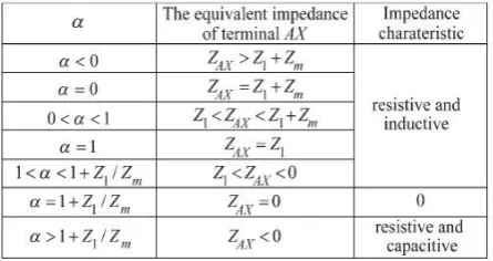
We have three cases here, in first case principle of variable reactor is verified, it means in place of microgrid we
employ two switches of impedance Z1 and Z2. Fig 8 record the transient current and voltage waveforms of the
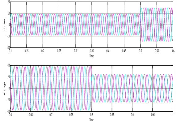
primary winding when α changes from 0.1 to 0.6 and from 0.6 to 1.In case-2 harmonic high penetration is
verified, here harmonics are injected at the supply side and a breaker is arranged with a timer of 1 minute and it
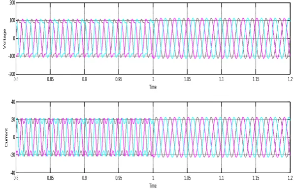
shows how harmonics are mitigated at supply side by using IPQC. In case-3 also harmonic high penetration is
verified, here harmonics are injected at the load side and a breaker is arranged with a timer of 1 minute and it
shows how harmonics are mitigated at load side by using IPQC.
Parameter Value
Ratio of series transformer 1:1
Magnetizing impedance Zm 16.309 ohm
Leakage impedance Z1 0.088 ohm
System voltage 172V
547 | P a g e
Passive filters (L3) 28.17mH
Capacitor(C3) 40 uF
Capacitor(C5) 20 uF
Inductor(L5) 20.28 mH
Table 2: System Parameters and Its Values
V. RESULTS
Discrete, Ts = 5e-005 s.
powergui v + -g A B C + -g A B C + -A B C
A B C a b c
A B C a b c
V
ab
c
Iab
c
A B C a b c Vabc Iabc A B C a b c Vabc IabcA B C a b c Vabc IabcA B C a b c Passive filters Subsystem3 microgrid Transformer Results Pulses V_conv Iabc Vabc V_mabc I_mabc Vdc I_Conv Isabc Vsabc gate
Fig 7: Simulation circuit to verify principle of variable reactor, harmonic isolation
0.1 0.15 0.2 0.25 0.3 0.35 0.4 0.45 0.5 0.55 0.6 -20 -10 0 10 20 Time C u r r e n t
0.6 0.65 0.7 0.75 0.8 0.85 0.9 0.95 1 -40 -20 0 20 40 Time V o lt a g e
Fig 8 :Current and voltage waveforms of the primary winding when α suddenly changes from 0.1 to 0.6 and 0..6
548 | P a g e
0.8 0.85 0.9 0.95 1 1.05 1.1 1.15 1.2
-200 -100 0 100 200 Time V o lt a g e
0.8 0.85 0.9 0.95 1 1.05 1.1 1.15 1.2
-40 -20 0 20 40 Time C u rr e n t
Fig 9 : Simulation waveforms when IPQC is not employed and after breaker applied and IPQC employed in
case-2
0.8 0.85 0.9 0.95 1 1.05 1.1 1.15 1.2 -200 -100 0 100 200 Time V o lt a g e
0.8 0.85 0.9 0.95 1 1.05 1.1 1.15 1.2 -40 -20 0 20 40 Time C u r r e n t
Fi
g 10:
Simulation waveforms when IPQC is not employed and after breaker applied and IPQC employed incase-3
VI. CONCLUSION
This paper presents a novel variable reactor based on the magnetic flux control. A transformer with air gap is
selected, and the primary winding current of the transformer is detected. A voltage-sourced inverter is applied to
follow the primary current to produce another current, which is injected to the secondary. When the injected
current is adjusted, the equivalent impedance of the primary winding of the transformer will change
continuously. The variable reactor features hardly producing harmonics, simple control scenario, and with
consecutive adjustable impedance. The ramp comparison current control with PI controller, which is suitable for
DSP microcontroller, is chosen as control current. In terms of the novel variable reactor, a novel IPQC suitable
for microgrid is proposed. The primary winding exhibits adjustable impedance, which plays the role of power
flow control, fault current limiter, and voltage compensation to fundamental. Meanwhile, the primary winding
exhibits high impedance to harmonic, which can greatly improve the source impedance to harmonics, and really
549 | P a g e
REFERENCES
[1] B. Lasseter, ―Microgrids [distributed power generation],‖ in Proc. IEEE Power Eng. Soc. Winter Meet.,
2001, vol. 1, pp. 146–149.
[2] C. Marnay, F. J. Robio, and A. S. Siddiqui, ―Shape of the microgrid,‖ in Proc. IEEE Power Eng. Soc.
Winter Meet., 2001, vol. 1, pp. 150–153.
[3] R. H. Lasseter et al., Integration of Distributed Energy Resources: The CERTS Microgrid Concept.
Berkeley, CA, USA: Consortium forElectric Reliability Technology Solutions, 2002.
[4] C. Marnay and O. Bailey, ―The CERTS microgrid and the future of the macrogrid,‖ Lawrence Berkeley
National Laboratory, Berkeley, CA, USA, Rep. LBNL-55281, Aug. 2004.
[5] N. Hatziargyriou, H. Asano, R. Iravani, and C. Marnay, ―Microgrids,‖ IEEE Power Energy Mag., vol. 5,
no. 4, pp. 78–94, Jul./Aug. 2007.
[6] R. H. Lasseter, ―Smart distribution: Coupled microgrids,‖ Proc. IEEE, vol. 99, no. 6, pp. 1074–1082, Jun.
2011.
[7] H. Akagi, E. H. Watanabe, and M. Aredes, Instantaneous Power Theory and Applications to Power
Conditioning. Piscataway, NJ, USA: IEEEPress, 2007, pp. 1–17.
[8] J. M. Guerrero, J. C. Vasquez, J. Matas, L. G. de Vicuna, and M. Castilla, ―Hierarchical control of
droop-controlled ac and dc microgrids—A general approach toward standardization,‖ IEEE Trans. Ind.
Electron., vol. 58, no. 1, pp. 158–172, Jan. 2011.
[9] M. Savaghebi, A. Jalilian, J. C. Vasquez, and J. M. Guerrero, ―Autonomous voltage unbalance
compensation in an islanded droopcontrolled microgrid,‖ IEEE Trans. Ind. Electron., vol. 60, no. 4, pp.
1390–1402, Jan. 2013.
[10] H. J. Laaksonen, ―Protection principles for future microgrids,‖ IEEE Trans. Power Electron., vol. 25, no.
12, pp. 2910–2918, Aug. 2010.
[11] J. M. Guerrero, P. C. Loh, T.-L. Lee, and M. Chandorkar, ―Advanced control architectures for intelligent
microgrids—Part II: Power quality, energy storage, ac/dc microgrids,‖ IEEE Trans. Ind. Electron., vol.
60, no. 4, pp. 1263–1270, Apr. 2013.
[12] T.-F. Wu, H.-S. Nien, C.-L. Shen, and T.-M. Chen, ―A single-phase inverter system for PV power
injection and active power filtering with nonlinear inductor consideration,‖ IEEE Trans Ind. Appl., vol.
41, no. 4, pp. 1075–1084, Jul./Aug. 2005.
[13] M. Azizi, A. Fatemi, M. Mohamadian, and A. Y. Varjani, ―Integrated solution for microgrid power