Pre-emptive Flow Installation for Internet of Things
Devices within Software Defined Networks
Peter Bull
Ron Austin
and Mak Sharma
School of Computing, Telecommunications and Networks
Birmingham City University Birmingham, UK Email: [email protected]
Abstract—The predicted prevalence of both Internet of Things
(IoT) based devices and the concept of Software Defined Net-working (SDN) as a new paradigm in netNet-working, means that consideration is required for how they will interact. Current SDN implementations operate on the principle that on receiving an unrecognised packet, a switch will query a centralised controller for a corresponding rule. Memory limitations within current switch devices dictate that this rule can only be stored for a short period of time before being removed, thus making it likely that the relatively infrequent data samples sent from IoT devices will have a transmission interval longer than this timeout.
This paper proposes a Pre-emptive Flow Installation Mecha-nism (PFIM) that dynamically learns the transmission intervals of periodic network flows and installs the corresponding rules within a switch, prior to the arrival of a packet. A proof-of-concept implementation shows this to have a significant effect on reducing the delay experienced by these flows.
I. INTRODUCTION
The Internet of Things (IoT) and Software Defined Net-working (SDN) have emerged in recent years as two areas of major research and development effort in the area of computer networking, and are set to change the way that networks function and interoperate. These two areas are often considered as separate entities, but their pervasive natures make the likelihood of their interaction at some levels to be certain. It is necessary to consider, therefore the implications of the characteristics of each and the affect of such interactions.
The concept of the Internet of Things refers to the net-working of a wide range of heterogeneous (often embedded) devices, to allow the sharing of data, and where appropriate, the reception of a data response, or actuating command. The exact nature of the data provided by these devices is likely to vary greatly, depending on the application in question (e.g. in room temperature sensors, industrial manufacturing process monitoring, etc.). This data will often have implicit perfor-mance requirements, including, but not limited to, ensuring that data samples are received in a timely manner. This places a requirement on the network and associated devices to support this performance.
Software Defined Networking differentiates from tradi-tional networking approaches through the separation of the data and control planes of the networks, thus allowing a greater
flexibility in network management and configuration. In an SDN based system, switches are essentially ’dumb’ devices that rely on a separate controller to provide rules for the way in which network flows should be handled. The switch and controller communicate via what is referred to as a southbound interface, with the majority of current implementations for this focusing on the Open Networking Foundation’s OpenFlow protocol standard. When a new packet arrives at a switch for which a rule does not exist, it is sent to the controller and a decision returned to the switch. These rules are held within the switch on either an Idle timeout (which will not expire while packets are still being received), or a Hard timeout (after which a rule will be deleted regardless of whether matching packets are still being received). These flow rules contain a large number of potential matching criteria (a maximum of 12 criteria in OpenFlow version 1.0 and 38 in version 1.5) and therefore require larger amounts of memory than a standard MAC address table. For this reason, idle timeout values for flow rules are often kept relatively short (in the region of sub-10 seconds), ensuring that memory is freed up once a flow has stopped transmitting.
As Software Defined Networking grows in prevalence it is increasingly likely that IoT gateway devices will function based on these principles. This will bring benefits in terms of flexibility in configuration and advanced Quality of Service management. The nature of current SDN devices may, how-ever, have a negative affect on the performance of IoT based devices, which are likely to send relatively small amounts of data at relatively infrequent intervals. Upon arrival of a new packet at a switch, the initial querying of a controller is subject to an additional delay, while a response is returned. If the Idle timeout period is smaller than the transmitting interval of the IoT device, then data packets will always be sent to the controller. If data samples are sent at regular periods, however, then this presents an opportunity to pre-emptively install flows before the sample arrives, thus reducing traffic sent to the controller and data packet latency.
performance characteristics. Section 6 concludes and discusses potential future work.
II. INTERNET OFTHINGSDEVICES ANDDATA CHARACTERISTICS
As noted by [1] and [2], the Internet of Things (IoT) has evolved from a large effort of research and development in previous projects, such as those focused on Wireless Sensor Networks, to recognise the fact that these networks cannot be seen as isolated islands, but should contribute, through the Internet, to a greater overall system infrastructure. Such an infrastructure provides greater opportunities for big data processing, intelligent control algorithms, and ultimately leads to systems that are more dynamic and responsive to changing conditions.
[3] discusses the range of pervasive devices or ’things’ that will contribute to the IoT, including, but not limited to embedded sensors, actuators, RFID tags, etc. The nature of these devices means that the traffic patterns that they create are inherently different than that currently seen across the majority of the Internet. As IoT devices are often battery powered, energy conservation is of high importance. For this reason, devices often spend large periods of time sleeping, waking only briefly to transmit, or receive data.
With the exponential rise in data traffic caused by the ever increasing number of IoT devices, the impact on the network architecture could be profound. Some sensors transmit data periodically, e.g. environmental sensors, whereas transport applications may require continuous transmission of engine data [4]. However, IoT devices in other scenarios (such as healthcare) have a wide and varied range and may require both quick burst and long burst data transmission.
Typically IoT devices access the Internet through a gate-way device. For those nodes not operating with standard IP addressing or associated protocols, this gateway can act as a translator between protocols. As the use of protocols such as 6LowPAN (IPv6 over Low power Wireless Personal Area Networks) expand, however, the role of the gateway reverts to that of a standard router.
Subsection II-A considers an example IoT scenario in further detail.
A. IoT Example Scenario
The Smart Care Spaces project, as proposed by [5], in-vestigates the use of IoT based technologies for the develop-ment of less formal environdevelop-ments for medical patient care. This is achievied through the use of sensors that monitor the patient’s environment and patient mounted sensors that monitor their physiological parameters, with an overall goal to providing physicians with data on which to base interventions or diagnoses. The devices used within this project range from wall mounted temperature and light sensors, to mobile phone based accelerometers and RFID based location tracking. Data samples from these devices are transmitted to a gateway device, which in turn forwards the data to a central point for cloud based decision making. This provides a good illustration of the variety of devices that could be in use within one small setting and the variety of data that would contribute to network
O N F W HIT E PA PER
Software-Defined Networking: The New Norm for Networks
7 of 12 © Open Networking Foundation. All rights reserved.
Introducing Software-Defined Networking
Software Defined Networking (SDN) is an emerging network architecture where network control is decoupled from forwarding and is directly programmable. This migration of control, formerly tightly bound in individual network devices, into accessible computing devices enables the underlying infrastructure to be abstracted for applications and network services, which can treat the network as a logical or virtual entity.
Figure 1 depicts a logical view of the SDN architecture. Network intelligence is (logically) centralized in software-based SDN controllers, which maintain a global view of the network. As a result, the network appears to the applications and policy engines as a single, logical switch. With SDN, enterprises and carriers gain vendor-independent control over the entire network from a single logical point, which greatly simplifies the network design and operation. SDN also greatly simplifies the network devices themselves, since they no longer need to understand and process thousands of protocol standards but merely accept instructions from the SDN controllers.
APPLICATION LAYER
CONTROL LAYER
INFRASTRUCTURE LAYER SDN Control Software
Network Device
Network Device Network Device
Network Device Network Device Business Applications
Network Services
Control Data Plane interface (e.g., OpenFlow)
API API
API
Perhaps most importantly, network operators and administrators can programmatically configure this simplified network abstraction rather than having to hand-code tens of thousands of lines of configuration scattered among thousands of devices. In addition, leveraging the SDN controller’s centralized intelligence, IT can alter network behavior in real-time and deploy new applications and network services in a matter of hours or days,
FIGURE 1 Software-Defined Network Architecture
Fig. 1. Software-Defined Network Architecture [10]
flows. When considering traffic patterns from these devices it is apparent that the majority of devices used in this scenario will likely be transmitting small and infrequent data samples. To take an example, a temperature sensor, such as the NXP LM75B temperature sensor [6] found on Arduino based sensor nodes has an output resolution of 11 bits. Data samples for temperature sensors also tend to be sent at relatively infrequent intervals as the overall temperature of a room will not change significantly in a small space of time.
To consider the healthcare scenario further, take the ex-ample of a major incident occurring on a motorway and all the emergency services are mobilised. All the vehicles on the motorway will have IoT type devices and passengers will have mobile devices connected to the internet by GSM or 4G. Now consider if a major accident had occurred, there will be an exponential change in data traffic as devices present at the scene will all be sending messages [7]. IoT enabled ambulances carrying patients to a nearby hospital could be be transmitting patient data from the incident to the hospital. In this scenario a wide variety of network traffic patterns are present and an adaptive network, capable of real-time response to changing network conditions is required.
III. SOFTWAREDEFINEDNETWORKING
When configuring traditional network devices (e.g. switches, or routers) the low level details of configuration and features etc. (referred to as the control plane) are dependent on the proprietary operating system of that device. This means that networks can be difficult to reconfigure in a dynamic manner, and complex to manage. Software Defined Networking (SDN), as discussed in [8], aims to address this through the decoupling of control and data planes to allow for the software based configuration of devices, illustrated in Figure 1. The high level architectural overview of SDN, provided by [9], goes on to detail how it consists of three main principles/components:
• Decoupling of controller and data planes
• Logically centralised control
These principles work together to facilitate the control and configuration of the network through a software based element, thus allowing all the associated advantages (such as dynamic control). A logically centralised controller provides a means of monitoring the overall network performance and dynamically adjusting configuration (be it re-routing traffic, or applying a new bandwidth rate limit to a greedy flow, etc.).
Implicit in a wide variety of SDN literature is the use of open standards as a means of facilitating greater interoperabil-ity. There are a small number of proprietary SDN implementa-tions, share the same architectural goals, but seek to leverage vendor-specific device capabilities to gain performance or functional advantages. Cisco, as an example, have proposed an Application Centric Infrastructure (ACI) [11]. Within an ACI based system, the network fabric consists of three major components: the Application Policy Infrastructure Controller, spine switches, and leaf switches. These components work together to manage both the application of network policies and the delivery of network traffic. Applications are specified with explicit performance requirements, for which it is the ACI networks responsibility to meet. Network applications can be developed through an open interface, however, device infras-tructure and low level network management is controlled by the Application Policy Infrastructure Controller. This approach leads to advantages in terms of network configuration and performance, however, limits the interoperability of devices. This paper will consider Software Defined Networks primarily from their more open standards based definition due to the wider overall applicability of developments in this area.
This section will consider aspects of SDN as they relate to the relevant Standards, Controllers, and Switch Devices. It concludes with a discussion of how these SDN principles relate to the Internet of Things.
A. SDN Standards
The abstraction of control and data planes found within Software Defined Networking means that standardised com-munication protocols are required. While a number of SDN standards have been proposed, the support within hardware has largely been found to be limited to two standards; OpenFlow and Cumulus Linux.
• The Open Networking Foundation (ONF) OpenFlow standard [12] defines the format of messages between the switch and controller. It also specifies a range of mandatory and optional network device features (e.g. flow matching criteria, VLAN tagging/detagging, ...). When a packet arrives at a switch it is checked against a flow table to identify the rules for how to treat that type of traffic. If a corresponding rule is not found in the flow table then the switch must communicate with a controller device using the OpenFlow protocol to request a rule for that flow.
The OpenFlow protocol has an active development community and user base, with new versions of the standard released periodically (version 1.5 being re-leased in December 2014). More recent versions (from 1.3 onwards) include additional Quality of Service based functionality (such as queue rate limiting) and provide a wider range of flow matching criteria.
• Cumulus Linux [13] is a network device Operating System, through which SDN objectives can be re-alised. Linux based applications can be built on top of this standard as a means of controlling the network behaviour. It is argued that the use of a Linux based Operating System for network devices provides a more open development environment, as device hardware does not need to be tailored towards a specific protocol (such as is necessary, for example, with OpenFlow).
As identified by [14], the current leading southbound inter-face in terms of wider community adoption and deployment is the Open Networking Foundation (ONF) OpenFlow standard. This is due to the fact that it is implementable on existing network switch hardware, whereas Cumulus Linux requires a different type of open platform based network device. Subsection III-C discusses the current implementation options for OpenFlow found within network switch devices.
B. SDN Controllers
An SDN controller is a logically centralised device that is capable of configuring network switches based on different flows observed within a network. This configuration tends to be sent as a reply to a query from a switch when it encounters a packet for which it does not currently have a corresponding rule. Messages between switch and controller must conform to a common standard, such as the previously mentioned OpenFlow. As the switch cannot perform any actions on incoming packets without having received a rule from the controller, the response time of the controller will have a large influence on overall network performance.
As identified by [14], there are a wide number of SDN controllers currently available (for example POX, NOX, Bea-con, Floodlight, Ryu), largely stemming from Open Source projects. These differ primarily in terms of choice of under-lying programming language and structure, and the effect that this has on performance (typically measured in number of flow installations per second).
As the control plane has been removed from SDN based network devices and placed within a software based controller, there is a need for replicating the advanced functionality of other network devices (e.g. routers, firewalls, load balancers). This has been termed Network Function Virtualisation (NFV). To implement the full range of network functionality solely within an SDN controller would be too complex to manage efficiently. To interface between the SDN controller and vir-tual network devices, another common interface is required, referred to as the Northbound Interface. Unlike the Southbound Interface, where a well-established standard (OpenFlow) ex-ists, work on a common Northbound Interface is ongoing.
space (or the same machine) as the controller. In addition, it offers the use of different southbound interfaces (for example OpenFlow, NETCONF, BGP, etc.) through plug-ins.
C. SDN Switch Devices
As SDN represents a new approach to networking, it follows that the switch devices that will form the major network component will also need adaptations to ensure their compatibility. There are currently three main options for switch devices, legacy switches running SDN enabled firmware, bare-metal switches, or fully virtualised switches.
• Traditional, legacy network switch devices (i.e. those supplied by the manufacturer with a custom, non-open source Operating System) are dependent on the switch manufacturer for software updates, and support for SDN based standards can therefore vary. Like-wise continued support for particular models is not guaranteed. There are, however, a number of switches commercially available through which support for OpenFlow can be enabled (usually through firmware update). As [14] notes, where support for SDN exists, the majority of current legacy devices support version 1.0 of the OpenFlow standard, with a growing number supporting version 1.3.
• Bare metal (otherwise referred to as white box) switches are supplied without an Operating System pre-installed. This allows the network designer to choose the Operating System that they will use. There are currently two major Operating Systems supported by bare metal switch manufacturers; PicOS (which supports OpenFlow) and Cumulus Linux.
• Virtualised SDN enabled switches allow for the con-struction of Software Defined Networks without a requirement for traditional networking hardware. Two common examples of these are OpenVSwitch and OFSoftSwitch (with OpenVSwitch also forming the basis of the support for OpenFlow within PicOS)
IV. SDNANDIOT
As mentioned in Section II, IoT devices typically commu-nicate through gateways, allowing access to other networks and the wider Internet. It is at these gateways that IoT traffic and SDN approaches will mix. The concept of SDN makes no requirements on the traffic sources within the network, and applications should therefore be able to remain agnostic to the underlying network infrastructure. This means that IoT devices would be able to send data through an SDN enabled device without any additional configuration required. This does not, however, place guarantees that all aspects of performance would be equivalent to that of a traditional network.
A major potential issue that presents is the delay introduced by an SDN enabled switch querying a controller for the installation of a corresponding rule. Within most traffic flows this additional delay would only be experienced in this initial setup process, while the rule is installed. The flow rules stored within a flow table on an SDN switch contain a large number of potential matching criteria (a maximum of 12 criteria in
OpenFlow version 1.0 and 38 in version 1.5) and therefore re-quire larger amounts of memory than a standard MAC address table. These rules could take between 12 and 243 bits to store for OpenFlow version 1.0 (assuming 6 bits are used for the port number, allowing up to 64 ports). This also assumes that a switch supports using a single bit to indicate wildcard matching criteria, as this is not mandatory within the OpenFlow standard, but dependent on vendor implementation. OpenFlow version 1.5 includes support for a wider range of criteria (including IPv6 addresses), resulting in a larger minimum of 38 bits and maximum of 1082 bits per rule. To address the potential memory issues that this creates, OpenFlow rules are typically set with a small Idle timeout value (in the region of below 10 seconds), meaning that if a flow has not transmitted within this time, then it is removed from the flow table.
Considering the relatively infrequent data sample transmis-sion found within IoT based devices discussed in Section II, and identified within the example scenario in Subsection II-A, it is likely that the Idle timeout value set at a switch will be smaller than common IoT device transmission intervals. This will result in an additional delay for the data packets every time that a data sample is sent, while the controller is queried for the matching rule. It will also place additional burden on the controller to deal with this request.
This additional delay for packets could have a serious impact on the performance of IoT systems. Taking the ex-ample of systems that contain both sensors and actuators, a finely balanced control algorithm, with soft or hard real-time deadlines, could malfunction given additional, unpredictable delays. If the TCP algorithm was used for transmissions then additional, excessive delay could be interpreted as loss, causing unnecessary retransmissions in the network.
Subsection IV-A considers Idle timeout values in further detail.
A. Analysis of Varying Idle Timeout Values in a Software Defined Network
A simple network simulation was created using Python scripting to allow an examination of the effect of varying Idle timeout on flow table sizes and the number of flow rules prematurely removed, before transmission has finished. Flow installations and removals are simulated based on the char-acteristics of network traffic being transmitted. Three traffic classes are used for this simulation; Continuous, Bursty, and Periodic.
• Continuous traffic transmit for a set period, with no breaks in transmission.
• Bursty traffic flows have periodic pauses for between 1 and 5 seconds (such as might be experienced with buffering data flows).
• Periodic flows have long breaks between transmission of between 5 and 30 seconds, such as is common with IoT sensor based devices.
0 10 20 30 40 50 60 70 N um ber of Flow R ul es Time (ms)
N u m b e r o f F l o w R u l e s I n s t a l l e d w i t h V a r y i n g I d l e T i m e o u t I n t e r v a l s ( O p e n F l o w 1 . 0 )
1 Second 3 Seconds 5 Seconds 10 Seconds 20 Seconds 0 1000 2000 3000 4000 5000 6000 7000 8000 Me m or y U se d (bi ts) Time (ms)
A m o u n t o f M e m o r y U s e d b y F l o w R u l e s w i t h V a r y i n g I d l e T i m e o u t I n t e r v a l s ( O p e n F l o w 1 . 0 )
1 Second
3 Seconds
5 Seconds
10 Seconds
20 Seconds
Fig. 2. Number of Flow Rules Installed - OF 1.0
display the more complex behaviours that would be found within real network traffic. For the purpose of this experiment the exact amount of data transmitted is not relevant, just the length of time that the flow is active for. Flow rule sizes are assigned pseudo-randomly between the minimum and maximum allowed for OpenFlow versions 1.0 and 1.5, as detailed in Subsection IV. This reflects the fact that both general and specific rules may be required.
The simulation ran for 120 seconds, with values taken at 1ms intervals. Idle timeout values of 1, 3, 5, 10, 15, and 20 were used for separate iterations of the simulation (note that a seed value was set to ensure that the pseudo-random values created for flow were maintained the same for each iteration).
Figure 2 shows the number of flow rules installed for each Idle timeout value using OpenFlow 1.0. From this it is clear that once a number of flows have begun starting and stopping transmission (as seen around 45 seconds into simulation), smaller intervals result in a much reduced number of flows in the flow table (with 43 rules installed with a 1 second Idle timeout, and 66 rules with a 20 second timeout at the end of the simulation). This is similarly evidenced in Figure 3, which gives an indication of the difference in memory usage these number of flow rules could make. Note that while a relatively small difference in overall size is observed here (between 4945 bits and 7402 bits after the simulation has completed), this would have a significant effect in real switches where flow count would be orders of magnitude larger than used in this simulation.
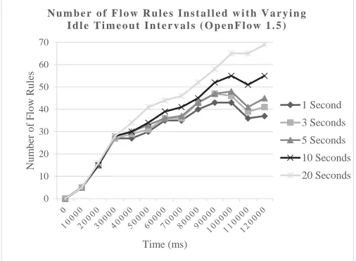
Figure 4 and Figure 5 show that the larger flow rule sizes found within OpenFlow 1.5 exacerbate this problem further, within an even greater difference between the size of flow tables with the different Idle timeout values.
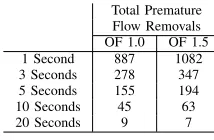
Table I shows the negative effect of the shorter timeout values, with a 1 second timeout resulting in 887 premature flow removals (using OpenFlow 1.0), and only 9 removals with a 20 second timeout. Each of these premature flow removals will result in additional delay for the packets involved and additional load on the controller. It is clear from this that
0 10 20 30 40 50 60 70 N um ber of Flow R ul es Time (ms)
N u m b e r o f F l o w R u l e s I n s t a l l e d w i t h V a r y i n g I d l e T i m e o u t I n t e r v a l s ( O p e n F l o w 1 . 0 )
1 Second 3 Seconds 5 Seconds 10 Seconds 20 Seconds 0 1000 2000 3000 4000 5000 6000 7000 8000 Me m or y U se d (bi ts) Time (ms)
A m o u n t o f M e m o r y U s e d b y F l o w R u l e s w i t h V a r y i n g I d l e T i m e o u t I n t e r v a l s ( O p e n F l o w 1 . 0 )
1 Second
3 Seconds
5 Seconds
10 Seconds
20 Seconds
Fig. 3. Amount of Memory Used by Flow Rules - OF 1.0
0 10 20 30 40 50 60 70 N um ber of Flow R ul es Time (ms)
N u m b e r o f F l o w R u l e s I n s t a l l e d w i t h V a r y i n g I d l e T i m e o u t I n t e r v a l s ( O p e n F l o w 1 . 5 )
1 Second 3 Seconds 5 Seconds 10 Seconds 20 Seconds 0 5000 10000 15000 20000 25000 30000 35000 40000 Me m or y U se d (bi ts) Time (ms)
A m o u n t o f M e m o r y U s e d b y F l o w R u l e s w i t h V a r y i n g I d l e T i m e o u t I n t e r v a l s ( O p e n F l o w 1 . 5 )
1 Second
3 Seconds
5 Seconds
10 Seconds
20 Seconds
Fig. 4. Number of Flow Rules Installed - OF 1.5
0 10 20 30 40 50 60 70 N um ber of Flow R ul es Time (ms)
N u m b e r o f F l o w R u l e s I n s t a l l e d w i t h V a r y i n g I d l e T i m e o u t I n t e r v a l s ( O p e n F l o w 1 . 5 )
1 Second 3 Seconds 5 Seconds 10 Seconds 20 Seconds 0 5000 10000 15000 20000 25000 30000 35000 40000 Me m or y U se d (bi ts) Time (ms)
A m o u n t o f M e m o r y U s e d b y F l o w R u l e s w i t h V a r y i n g I d l e T i m e o u t I n t e r v a l s ( O p e n F l o w 1 . 5 )
1 Second
3 Seconds
5 Seconds
10 Seconds
20 Seconds
selecting an appropriate timeout value will need to be balanced based on application requirements and switch device memory resource availability. This is not an ideal solution, however, and thus an alternative mechanism that would support both the lower memory utilisation of the small timeout values, and the low number of premature flow removals found with larger timeouts is required.
TABLE I. TOTALPREMATUREFLOWREMOVALS
Total Premature Flow Removals
OF 1.0 OF 1.5
1 Second 887 1082
3 Seconds 278 347
5 Seconds 155 194
10 Seconds 45 63
20 Seconds 9 7
V. A PROPOSEDPRE-EMPTIVEFLOWINSTALLATION MECHANISM(PFIM)
The problems identified in Subsection IV relate to the fact that flow rules are not present within the flow table at the time in which packets arrive. If data samples are being transmitted at regular periods, however, then it should be possible to pre-emptively install the flow prior to the packets arrival.
[16] uses pre-emptive flow installation as a means of ensuring that real-time applications are scheduled appropri-ately within the network, allowing them to complete within the deadlines required (and not scheduling tasks that will miss deadlines and waste network resources). This approach, however, requires explicit knowledge of the application perfor-mance requirements/characteristics, thus is not readily appli-cable to IoT based systems as it would hinder their dynamic construction.
A Pre-Emptive Flow Installation Mechanism (PFIM) is thus proposed that will dynamically learn the periodic patterns of IoT based traffic and install flows within an SDN based switch, prior to the arrival of packets. This mechanism is formed of three main components; flow monitoring, flow periodicity checking, and flow installation.
Flow monitoring requires that the controller monitors and records the time of arrival of packets, or more specifically, the request from a switch to a controller for a rule associated with a packet. A flow should be identified here, as shown in Algorithm 1, based on source IP address, port number and switch identification.
On packet in;
flow = SourceIPAddress:SourcePortNumber:SwitchID; ifflow is new then
create flow record; record packet arrival time; else
flow record exists;
append packet arrival time to flow record; end
Algorithm 1: PFIM Flow Monitoring
Flow periodicity checking is necessary to establish whether packets from a flow are arriving at regular intervals. While
it may be possible to establish complex patterns through a pattern recognition algorithm, this work focuses on those flows that transmit at regular intervals. This will help to reduce the computational load on the controller, and therefore limit associated effects on delay. Algorithm 2 shows how periodicity is established once a sufficient number of samples has been observed, and if a baseline standard deviation threshold not exceeded. The exact value used for this threshold will be dependent on the timing accuracy of the devices generating traffic within a particular system.
foreach record in flow recordsdo
ifnumber of times observed >minimum number of samplesthen
Calculate mean of times;
Calculate standard deviation of times; ifstandard deviation <thresholdthen
Store flow installation timing requirements; end
end end
Algorithm 2: PFIM Flow Periodicity Check
Algorithm 3 details the flow installation procedure, whereby flows are installed at a pre-set amount of time before they are due to arrive at the switch. Note that the amount of time prior to packet arrival that a flow is installed could be calculated based on the maximum variance in packet arrival times, and the maximum delay in transmitting and installing the flow within the switch, but that is outside the scope of this work. For the purposes of later experimentation, this is taken as a fixed value.
On timer expiration;
foreach record in flow recordsdo
if(current time + pre-empt value) - previous flow installation time>= flow meanthen
Send flow installation message to switch; end
end
Algorithm 3: PFIM Flow Installation
OpenFlow protocol version 1.5 introduces the concept of scheduled bundle messages. These are messages that can be sent to a switch to be activated at a specific time. This could allow the PFIM to send scheduled flow installation messages for periodic flows at any time before installation is required, without the flow being installed and expiring prematurely. As mentioned in Section III, however, support for implementations of the OpenFlow protocol is currently limited to versions 1.0 and 1.3, so this is not currently possible to implement.
0 5 10 15 20 25 30
0 5
10 15 20 25 30 35 40 45 50 55
R
T
T
D
el
ay
(m
s)
Data Sample Number
R T T D e l a y o f P F I M v s S t a n d a r d L 3 L e a r n i n g C o n t r o l l e r
Standard L3 Learning Controller
L3 Learning Controller with PFIM
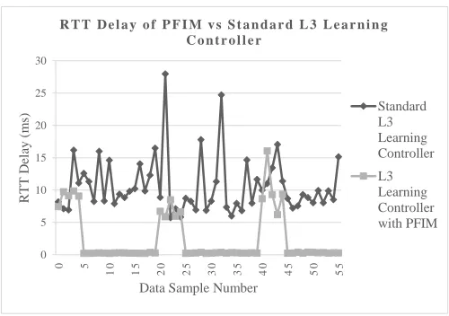
Fig. 6. RTT Delay of PFIM vs Standard L3 Learning Controller
for all complex network topologies, simpler topologies, such as used here, have been successfully validated. Additionally results can be taken as general indications of performance, rather than strict identifiers of values that can be observed from a real hardware-testbed.
For the purposes of this experimentation the ping tool was used to generate packets from Host 1 to send to Host 2 at a period of once every 5 seconds and measure the total Round Trip Time (RTT). This generates a single flow, which can then be clearly analysed for performance. The Idle timeout value for flow rules was set to 1 second, as this was observed in Subsection IV-A as providing the best performance in terms of memory utilisation.
For this experiment, 5 occurrences of a flow installation request were observed before deciding whether a flow was transmitting periodically. In a real implementation, experimen-tation would be required to determine the minimum number of packet instances received in order to determine accurately whether a flow was periodic.
Flows were installed 500ms before a packet was due to arrive at a switch to allow for variations in packet arrival times. In further implementation this could be refined further based on the jitter tolerance allowed for flows to be considered periodic.
Flows stopped being installed pre-emptively after 15 in-stallations, to allow for the fact that the source may have stopped transmitting, after which, the controller started the packet observation process from the beginning. The number of pre-emptive installations performed will be system dependent, but could also increase the longer that a flow remains active.
Figure 6 shows a comparison between using a standard L3 learning controller, and the controller using the proposed PFIM. Clear patterns can be seen where the controller is observing the packet arrivals, and once pre-emptive flow instal-lations begin, the RTT delay experienced drops significantly, from around 10ms to less than 1ms. Likewise the variation in delay can be seen to reduce as the controller is not needing to be queried upon every packet arrival at the switch.
VII. CONCLUSION ANDFUTUREWORK
This paper has presented a discussion of potential per-formance issues that may arise from the combination of IoT device traffic patterns and current SDN implementations. Through the introduction of a proposed Pre-emptive Flow Installation Mechanism it has been shown that the patterns of periodic data transfers can be observed by a controller and flow rules installed prior to the arrival of packets at a switch, thus negating the added delay that comes from querying a controller. This has been demonstrated through a proof of concept implementation within the POX controller framework. Future work will focus on testing within larger topologies, across multiple switches, and within a hardware-based test-bed. This will include the mixing of IoT device traffic with other real network traffic as a means of observing the resulting behaviour and adapting the proposed mechanism accordingly.
REFERENCES
[1] L. Mainetti, L. Patrono, and A. Vilei, “Evolution of wireless sensor networks towards the Internet of Things: A survey,” in2011 19th Inter-national Conference on Software, Telecommunications and Computer Networks (SoftCOM), 2011, pp. 1–6.
[2] J. Gubbi, R. Buyya, S. Marusic, and M. Palaniswami, “Internet of Things (IoT): A vision, architectural elements, and future directions,” Future Generation Computer Systems, vol. 29, no. 7, pp. 1645–1660, 2013.
[3] L. Atzori, A. Iera, and G. Morabito, “The Internet of Things: A survey,” Computer Networks, vol. 54, no. 15, pp. 2787–2805, 2010.
[4] W. He, G. Yan, and L. D. Xu, “Developing vehicular data cloud services in the IoT environment,”IEEE Transactions on Industrial Informatics, vol. 10, no. 2, pp. 1587–1595, 2014.
[5] A. Thomas, P. Moore, C. Evans, H. Shah, M. Sharma, S. Mount, F. Xhafa, H. Pham, L. Barolli, A. Patel, A. Wilcox, C. Chapman, and P. Chima, “Smart care spaces: pervasive sensing technologies for at-home care,” International Journal of Ad Hoc and Ubiquitous Computing, vol. 16, no. 4, pp. 268–282, 2014.
[6] NXP, “LM75B - Digital temperature sensor and ther-mal watchdog,” Tech. Rep., 2015. [Online]. Available: http://www.nxp.com/documents/data sheet/LM75B.pdf
[7] M. P. R. S. Kiran, P. Rajalakshmi, K. Bharadwaj, and A. Acharyya, “Adaptive rule engine based IoT enabled remote health care data acquisition and smart transmission system,” in2014 IEEE World Forum on Internet of Things, WF-IoT 2014, 2014, pp. 253–258.
[8] Y. Jarraya, T. Madi, and M. Debbabi, “A Survey and a Layered Taxonomy of Software-Defined Networking,” IEEE Communication Surveys & Tutorials, vol. 16, no. 4, pp. 1955–1980, 2014.
[9] Open Networking Foundation, “SDN Architecture Overview version 1.1,” Tech. Rep., 2014.
[10] Open Networking Foundation, “Software-Defined Networking: The New Norm for Networks,” Tech. Rep., 2012.
[11] Cisco, “Application Centric Infrastructure Overview: Implement a Ro-bust Transport Network for Dynamic Workloads,” Tech. Rep., 2013. [12] Open Networking Foundation, “OpenFlow Switch Specification version
1.0,” Tech. Rep., 2009.
[13] Cumulus Linux, “Cumulus Linux 2.5.1 - User Guide,” Tech. Rep., 2015. [14] D. Kreutz and F. Ramos, “Software-Defined Networking: A Comprehensive Survey,” arXiv preprint arXiv: . . ., p. 49, 2014. [Online]. Available: http://arxiv.org/abs/1406.0440
[15] Linux Foundation, “OpenDaylight - An Open Source Community and Meritocracy for SoftwareDefined Networking,” Tech. Rep., 2013. [16] L. Liu, J. Li, and J. Wu, “TAPS: Task-aware preemptive flow
schedul-ing,” in IEEE 20th International Workshop on Local & Metropolitan Area Networks (LANMAN), 2014, pp. 1–2.
![Fig. 1.Perhaps most importantly, network operators and administrators can Software-Defined Network Architecture [10]](https://thumb-us.123doks.com/thumbv2/123dok_us/1015920.1601551/2.612.321.571.55.220/importantly-network-operators-administrators-software-dened-network-architecture.webp)