[Okoye et al., 5(12): December, 2018]
ISSN 2349-0292
Impact Factor 3.802
GLOBAL JOURNAL OF ADVANCED ENGINEERING TECHNOLOGIES AND
SCIENCES
DEVELOPMENT AND TESTING OF THREE-PHASE AUTOMATIC PHASE
DISCRIMINATOR
Olowofela, S. S., Okoye, C. U. and Lawal, A. S
*Department of Electrical / Electronics Engineering
The Federal Polytechnic Ilaro, Ogun State. Nigeria
Corresponding Author: Olowofela, S.S.
DOI: 10.5281/zenodo.2449317
ABSTRACT
Power supply in Nigeria has degraded to a level that many residential buildings now have three or two power supply lines connected to each building(big or small) at the usual nominal 240V a.c supply. The standard practice in a developed country where there is stable and reliable power is to have one single phase line in a typical small building. Usually, a Nigerian consumer in this setting connected to three phase manually transfers the fuse to an active line or phase where there is quality power. This manual engagement, though unacceptable is dangerous to life and property. It is also time-wasting. A better work can be done by using a three phase automatic phase discriminator. The device displays the voltage level available on each of the phases connected to the house and then switches on to the one with high quality power output. A programmed intelligent microcontroller PIC16F877A was used. The device was also subjected to continuity test during which contactors and relay coils showed low resistances at their terminals. Finally, the circuit was simulated on Proteus and Electronics Software to further confirm its workability and efficiency. The overall performance was very good.
KEYWORDS: Micro-controller, PIC16F877A, Proteus, Relay, Contactors.
INTRODUCTION
Constant reliable and quality power supply is the desire of an average consumer anywhere. This is because, the development of any nation depends so much on availability and reliability of electricity in that nation. Unfortunately, Nigeria and many African countries are under-developed because electricity supply to them is quite poor in quality and quantity. (Harpuneet & Harjeet, 2012). All over the world studies (Nweke & Iwu, 2005; Adebayo & Yusuf, 2013) have shown that economy of a nation grows in unison with growth in electricity production and use.
However, since constant, good quality power supply to all classes of consumers in Nigeria is very uncertain, most consumers have devised some means of optimizing the electricity or power made available in a given locality. It is a common knowledge that even very small consumers connect three phases of supply to as small as a room apartment with a view to manually transferring the fuse to any one phase that is alive with good quality power or voltage at any particular time. This, however is an unacceptable practice in a developed world because, apart from causing system voltage imbalance, it could also pose some danger to lives and property (Adedokun & Osunpidan, 2010; Oduobuk, et al, 2014).
An automatic phase discriminator was developed and deployed to select a suitable phase out of the three phases of the power supply having suitable voltage level. The voltage level in each phase is displayed on the Liquid Crystal Display (LCD) and the phase with the most suitable phase voltage is engaged automatically. In this way, the consumer is switched to the supply with better power quality without the use of mere hand.
METHODOLOGY
[Okoye et al., 5(12): December, 2018]
ISSN 2349-0292
Impact Factor 3.802
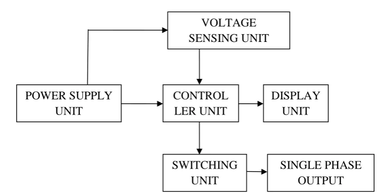
The hardware part of the work involves the circuitry design that senses signals from the supply and acting on it to switch the supply to the output load from one phase to another, depending on the availability and signal quality. However, the circuit design comprises of the following units as shown in the block diagram below. Power supply unit Voltage sensing unit Controller unit Switching unit Display unit
Figure 1.0: Block diagram of the automatic phase discriminator
DEVELOPMENT PROCEDURE
Power Supply UnitThe power supply unit serves as the input unit to the system. It converts the A.C input to D.C and it comprises of the following components.
Transformer: It steps down or step up A.C input signal. It is used in this project to step down 220v to 15v A.C by the principles of electromagnetic induction. (Oduobuk et al 2014).
Bridge rectifier (diode): It converts an alternating voltage to a direct voltage. It performs a full wave rectification of output voltage from the transformer.
Capacitor: It stores charges. It filters the output of bridge diode to eliminate ripples in the output signal. Regulator: This component regulates the input signal to a stable unchanging voltage. It has 3 terminals.
For this work, the regulator converts the input voltage to a constant 5v that is eventually connected to the controller. (Stan,2002).
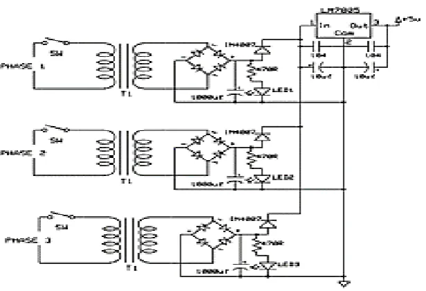
The circuit diagram of the regulated power supply is shown in Fig. 2.0 below.
The alternating input signal (220V ac) is fed into the primary side of the transformer and the voltage is stepped down to 15V which is the required voltage for the circuit. This 15V (an alternating voltage) is then rectified using a full wave rectifying device (i.e. the bridge diode); capacitor is used to remove ripples in the output voltage. The essence of this is to convert the AC voltage from the main source to DC voltage because the micro-controller, the power relay, the LCD and some other component are powered by a DC source. The microcontroller requires just 5V for its operation and hence, a regulator is required. The filtered output is then supplied to the regulator that gives a constant output of 5V required by the microcontroller. (Khairul & Husnain, 2011).
[Okoye et al., 5(12): December, 2018]
ISSN 2349-0292
Impact Factor 3.802
Figure 2.0: Circuit diagram of the power supply unit
The step-down transformer reduces the AC input from 220V to 15V. The 15V A.C is then rectified using bridge rectifier to convert it to DC. After the conversion, the DC value is as given below:
If 𝐴𝐶 𝑣𝑜𝑙𝑡𝑎𝑔𝑒 = 𝑉𝑎𝑐 = 15𝑣 (secondary voltage)
& 𝐷𝐶 𝑉𝑜𝑙𝑡𝑎𝑔𝑒 = 𝑉𝑑𝑐
& 𝐷𝑖𝑜𝑑𝑒 𝑣𝑜𝑙𝑡𝑎𝑔𝑒 = 𝑉𝑑 (Constant 0.7v, Forward bias voltage)
𝑡ℎ𝑒𝑛, 𝐷𝑐 𝑣𝑜𝑙𝑡𝑎𝑔𝑒 𝑉𝑑𝑐 = 𝑉𝑎𝑐√2 − 2𝑉𝑑(Stan, 2002)
𝑓𝑟𝑜𝑚 𝑡ℎ𝑒 𝑐𝑖𝑟𝑐𝑢𝑖𝑡 𝑑𝑖𝑎𝑔𝑟𝑎𝑚 𝑖𝑛 𝑓𝑖𝑔𝑢𝑟𝑒 2, 𝑉𝑎𝑐 = 15𝑣 𝑎𝑛𝑑 𝑉𝑑 = 0.7𝑣 𝑉𝑑 𝑖𝑠 𝑡ℎ𝑒 𝑑𝑖𝑜𝑑𝑒 𝑓𝑜𝑟𝑤𝑎𝑟𝑑 𝑏𝑖𝑎𝑠 𝑣𝑜𝑙𝑡𝑎𝑔𝑒
𝐼𝑛 𝑓𝑜𝑟𝑤𝑎𝑟𝑑 𝑏𝑖𝑎𝑠 𝑎𝑛𝑑 𝑟𝑒𝑣𝑒𝑟𝑠𝑒 𝑏𝑖𝑎𝑠 𝑜𝑓 𝑡ℎ𝑒 𝑏𝑟𝑖𝑑𝑔𝑒 𝑑𝑖𝑜𝑑𝑒, 𝑜𝑛𝑙𝑦 𝑡ℎ𝑒 𝑡𝑤𝑜 𝑜𝑓 𝑡ℎ𝑒 𝑓𝑜𝑢𝑟 𝑑𝑖𝑜𝑑𝑒𝑠 𝑐𝑜𝑛𝑑𝑢𝑐𝑡. 𝐻𝑒𝑛𝑐𝑒, 2𝑉𝑑 𝑖𝑠 𝑢𝑠𝑒𝑑
𝑉𝑑𝑐 = 15√2 − 2(0.7) 𝑉𝑑𝑐 = 19.81𝑉
Also, 1000μF capacitor is used to produce a large and fairly steady dc voltage. It charges up to the peak value of the applied ac voltages and then discharges slowly depending on the time-constant. The value of this capacitor is chosen based on the calculation below.
𝑅𝑒𝑐𝑎𝑙𝑙, 𝐼 = 𝐶𝑑𝑣 𝑑𝑡⁄
∴ 𝐶 = 𝐼𝑑𝑡 𝑑𝑣⁄
𝑇 = 1 𝑓⁄
𝐼𝑓 𝑓 = 50𝐻𝑧, 𝑡ℎ𝑒𝑟𝑒𝑓𝑜𝑟𝑒, 𝑇 = 0.02𝑠(𝑇 𝑖𝑠 𝑡ℎ𝑒 𝑡𝑖𝑚𝑒 𝑡𝑜 𝑐𝑜𝑚𝑝𝑙𝑒𝑡𝑒 𝑜𝑛𝑒 𝑐𝑦𝑐𝑙𝑒)
𝑑𝑡 𝑖𝑠 𝑡ℎ𝑒 𝑡𝑖𝑚𝑒 𝑓𝑜𝑟 𝑡ℎ𝑒 𝑐𝑎𝑝𝑎𝑐𝑖𝑡𝑜𝑟 𝑡𝑜 𝑑𝑖𝑠𝑐ℎ𝑎𝑟𝑔𝑒 𝑢𝑝 𝑡𝑜 𝑤ℎ𝑒𝑛 𝑖𝑡 𝑤𝑖𝑙𝑙 𝑠𝑡𝑎𝑟𝑡 𝑡𝑜 𝑐ℎ𝑎𝑟𝑔𝑒 𝑢𝑝 𝑎𝑔𝑎𝑖𝑛.
𝐻𝑒𝑛𝑐𝑒, 𝑑𝑡 = 10𝑚𝑠 = 0.01𝑠( 𝑖𝑠 𝑡ℎ𝑒 𝑡𝑖𝑚𝑒 𝑡𝑜 𝑐𝑜𝑚𝑝𝑙𝑒𝑡𝑒 ℎ𝑎𝑙𝑓 𝑐𝑦𝑐𝑙𝑒)
𝑑𝑣 = 𝑉𝑑𝑐 − 𝑒𝑥𝑝𝑒𝑐𝑡𝑒𝑑 𝑣𝑜𝑙𝑡𝑎𝑔𝑒
𝑐ℎ𝑜𝑜𝑠𝑖𝑛𝑔 15𝑣 𝑎𝑠 𝑡ℎ𝑒 𝑒𝑥𝑝𝑒𝑐𝑡𝑒𝑑 𝑣𝑜𝑙𝑡𝑎𝑔𝑒 𝑡𝑜 𝑡ℎ𝑒 𝑟𝑒𝑔𝑢𝑙𝑎𝑡𝑜𝑟, 𝑡ℎ𝑒𝑛
𝑑𝑣 = (19.81 − 15)𝑣 𝑑𝑣 = 4.81𝑣
𝐼 𝑖𝑠 𝑡ℎ𝑒 𝑡𝑜𝑡𝑎𝑙 𝑐𝑢𝑟𝑟𝑒𝑛𝑡 𝑟𝑒𝑞𝑢𝑖𝑟𝑒𝑑 𝑏𝑦 𝑡ℎ𝑒 𝑐𝑖𝑟𝑐𝑢𝑖𝑡 𝑡𝑜 𝑝𝑜𝑤𝑒𝑟 𝑡ℎ𝑒 𝑟𝑒𝑙𝑎𝑦𝑠, 𝑚𝑖𝑐𝑟𝑜𝑐𝑜𝑛𝑡𝑟𝑜𝑙𝑙𝑒𝑟, 𝐿𝐶𝐷, 𝑟𝑒𝑔𝑢𝑙𝑎𝑡𝑜𝑟 𝑎𝑛𝑑 𝑜𝑡ℎ𝑒𝑟 𝑐𝑜𝑚𝑝𝑜𝑛𝑒𝑛𝑡.
𝑐𝑢𝑟𝑟𝑒𝑛𝑡 𝑓𝑜𝑟 𝑚𝑖𝑐𝑟𝑜𝑐𝑜𝑛𝑡𝑟𝑜𝑙𝑙𝑒𝑟 = 100𝑚𝐴 𝑐𝑢𝑟𝑟𝑒𝑛𝑡 𝑓𝑜𝑟 𝑟𝑒𝑔𝑢𝑙𝑎𝑡𝑜𝑟 = 10𝑚𝐴
[Okoye et al., 5(12): December, 2018]
ISSN 2349-0292
Impact Factor 3.802
𝑇𝑜𝑡𝑎𝑙 𝑐𝑢𝑟𝑟𝑒𝑛𝑡 = 1660𝑚𝐴
For the capacitor, 1000μF was chosen to cater for any exceptional condition that can be caused by the manufacturer, temperature and others. The LM7805 regulator is chosen so as to provide a perfect steady 5V to the microcontroller. The microcontroller uses 5V voltage to work effectively.
When only one of the phases is available, the system is powered from the supply attached to the phase. But, if more than one phase is available, the supply is connected in parallel to the system, thereby selecting the most suitable phase.
Voltage Sensing Unit.
The microcontroller senses/monitor the input AC voltage from the three phase power supply. The microcontroller senses these voltages through its analog-to-digital converter port (ADC port).
An Analog to Digital Converter (ADC) is a very useful feature that converts an analog voltage on a pin2, 3 & 4 to a digital signal. By converting the analog signal to digital signal, analog input is converted into a digital signal that can be stored and processed in the microcontroller.
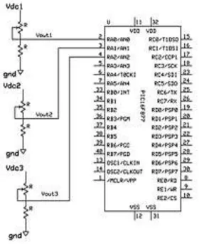
Figure 3 below shows the circuit diagram of the voltage sensing unit.
The unit consists of two resistors (a fixed and a variable resistor) connected in series across the rectified voltage from each phase.
Vdc = 15v, and Vdc corresponds to the AC input voltage.
𝑅1 = 10𝐾, 𝑅2 = 4.7𝐾
𝑉𝑜𝑢𝑡 = 𝑉𝑑. 𝑅2
𝑅1 + 𝑅2
𝑉𝑜𝑢𝑡 = 15 . 4.7𝑘
10𝑘 + 4.7𝑘 ∴ 𝑉𝑜𝑢𝑡 = 4.8𝑣
The maximum dc voltage equivalent to the AC input voltage that will be connected to the ADC ports of the microcontroller is 4.8v.
Note: Vin = Vdc
[Okoye et al., 5(12): December, 2018]
ISSN 2349-0292
Impact Factor 3.802
Figure 4.0: connection of the voltage sensing unit to the ADC ports of the microcontroller
Control Unit
Microcontrollers (also known as embedded controllers) are microcomputers. Unlike personal computers, microcontrollers are computers that are designed to carry out a specific function. However, microcontrollers are not used on their own; they are embedded in other computer or machine. They carry out their functions by taking inputs from the devices they are incorporated into.
PIC16F877A is one of the most popular PIC micro-controllers. It comes in a 40-pin dual in-line package (DIP) with internal peripherals. The 40 pins make it easier to use the peripherals as the functions are spread out over the pins. PIC16F877A is a powerful (200 nanosecond instruction execution) easy-to-program (only 35 single word instructions) CMOS FLASH-based 8-bit micro-controller. It is upward compatible with the PIC16C5X, PIC12CXXX and PIC16C7X devices.
The PIC16F877A is characterized by 256 bytes of EEPROM data memory, self-programming, an ICD, 2 comparators, 8 channels of 10-bit Analog-to-Digital (A/D) converter, 2 capture/compare/PWM functions, the synchronous serial port which can be configured as either 3-wire Serial Peripheral Interface (SPI) or the 2-wire Inter-Integrated Circuit (PC) bus and a Universal Asynchronous Receiver Transmitter (USART). All of these features make it ideal for more advanced level A/D applications: automotive, industrial, appliances and consumer applications. One of the main advantages is that each pin is only shared between two or three functions although an external crystal oscillator chip is required to generate the required clock signal.
[Okoye et al., 5(12): December, 2018]
ISSN 2349-0292
Impact Factor 3.802
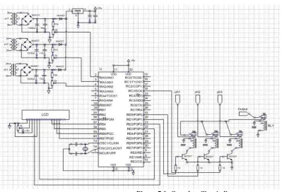
It senses and monitor the input voltages of a three phase power supply through its ADC Ports (pin 2,3and 4)
It acts as a switch to ON or OFF devices connected to the output in response to the quality of the phases. This control is done through digital pin RD0, RDI and RD2 (pin 19,20 and 21).
Switching Unit.
The switching unit comprises of transistor used as a relay driver and the relay.
Relay is an electrically operated switch. Many relays use an electromagnet to operate a switching mechanism. Relay is applicable where it is necessary to control a circuit requiring a low power signal or where several circuits must be controlled by one signal.
The parts of every relay include the following:
Electromagnet which becomes a magnet when it receives an electric signal. Armature that can be attracted by the electromagnet.
Spring which pulls the armature when the electromagnet is demagnetized. Sets of electrical contacts
The relay is used to isolate both the controlling and the controlled device. The relay is an electromagnetic device, which consists of solenoid, moving contacts (switch) and restoring spring. Hence it is possible for the interface IC to drive the relay satisfactorily. To enable this, a driver circuitry is employed which act as a buffer circuit. The driver circuitry senses the presence of a “high” level at the input and drives the relay from another voltage source. Hence the relay is used to switch the electrical supply to the appliances.
A transistor (BC547) is used as a buffer to drive the relay. Since microcontroller can provide only 25mA at its output, it cannot provide sufficient supply for a relay coil which is approximately 500mA; a transistor is used for adjustment purposes. The signal from the microcontroller output is used to bias the transistor through 4.7kΩ resistor.
Display Unit
The LCD module acts as textual information to the user. It is like a monitor hooked to the gadget to show textual information on the operation of the device. A 16 by 2 LCD type is used in this work. It has two rows and sixteen columns. It is used to show information on the operation and status of the controller and the controlled device. The LCD is connected to port B of the microcontroller which sends information to be displayed through its PGD and PGC pins (pin 39 and 40). It is put into operation by a regulated 5V as well as its backlight. The backlight contrast is controlled through pin 3 of the LCD via a variable resistor of 10kΩ.
The pin connection of the 16*2 LCD is as follows and is shown in Fig.5 below. Pin 1 GND
Pin 2 +5V Pin 3 VEE Pin 4 RS Pin 5 RD Pin 6 EN Pin 11 D4 Pin 12 D5 Pin 13 D6 Pin 14 D7
[Okoye et al., 5(12): December, 2018]
ISSN 2349-0292
Impact Factor 3.802
Figure 5.0: LCD circuit diagram
Single Phase output
This is a section of the system where the Load is connected. It comprises four different 15V coil-electromagnet controlling 250V A.C relays. The relay has a current rating of 120A since it is designed to carry a maximum Load of 100A.They were all connected to the micro-controller through the base of the Transistors.
Figure 6.0: Relay circuit diagram.
[Okoye et al., 5(12): December, 2018]
ISSN 2349-0292
Impact Factor 3.802
RESULTS AND DISCUSSION
Figure 8.0: Output wave form Oscilloscope
Figure 8.0 above displays the output to scenario (1 1 0), that is the Red phase is set high, Yellow phase is also set high and Blue phase is set low as depicted in figure 9.0, at 50Hz, 20ms.
Figure 9.0: Displayed value for logic Output 1 1 0
The L.C.D display in figure 9.0, describes the logic state of three different phases, red phase with 255V at logic 1, Yellow phase, 249V at logic 1 and Blue phase with 054V at logic 0. However, the controller selects the best available which is Red phase (PHS 1: 255V) to switch on the load circuit.
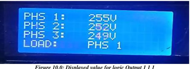
Figure 10.0: Displayed value for logic Output 1 1 1
[Okoye et al., 5(12): December, 2018]
ISSN 2349-0292
Impact Factor 3.802
Figure 11.0: Output wave form Oscilloscope
Figure 11.0, is the sinusoidal waveform displayed by the oscilloscope on connecting it to the load circuit as supplied by the Yellow phase of figure 12.0 The wave is not a perfect sine wave due to fluctuation from the supply.
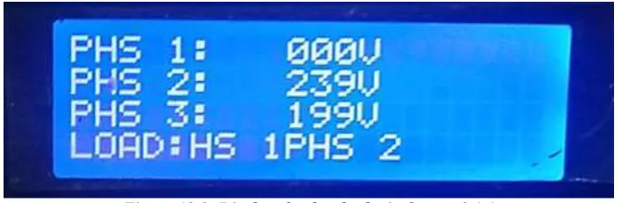
Figure 12.0: Displayed value for logic Output 0 1 1
Figure 12.0 shows another scenario in which the Red phase is Off, Yellow phase is 239V and Blue phase is 199V. The controller selects the Yellow phase to supply the load circuit as earlier started.
Figure 13.0: Output wave form Oscilloscope
[Okoye et al., 5(12): December, 2018]
ISSN 2349-0292
Impact Factor 3.802
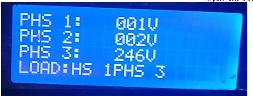
Figure 14.0: Displayed value for logic Output 0 0 1
Figure 14.0 is another scenario of Red phase being 0 or low (001V), Yellow phase being 0 or low (002V) and Blue phase being high at 246V. The controller is able to compare and select the best which is the blue phase (PHS 3: 246V) to supply to the output load. However, the truth tables below show cases the result of all other scenarios at a glance.
Table 1: Summary of the Output results
CONCLUSION
The development and testing of a three-phase automatic phase discriminator was carried out which is capable of automatically switching on to any one phase of the three phases alive with suitable power quality. The device auto-monitors each of the three phases sequentially and switches over to the phase with the required voltage level (without human effort). The performance test on the device was carried out in the laboratory. The output voltage as displayed on the oscilloscope was sinusoidal in shape. Due to fluctuations in supply, the relay rapidly selected the most desirable voltage for display. This, it did, by comparing the output of the three phase supply fed into it from public utility and switching on automatically to the phase with the highest (suitable) voltage for use by the load.
[Okoye et al., 5(12): December, 2018]
ISSN 2349-0292
Impact Factor 3.802
Journal of Engineering and Technology Research Vol. 2, No. 4, April 2014, pp. 1 - 15, ISSN: 2327 - 0349 (Online) Available online at www.ijeatr.org[3] Harpuneet Singh and Harjeet Singh Manga (2012), Impact of Unreliable Power on a Paper Mill: A Case Study of Paper Industry of Punjab, India. Proceeding of the International Multi Conference of Engineers
and Computer Scientist. Retrieved: 08/06/2013.
http://www.journal.au.edu/au_techno/2007/oct07/auJournalV11N2_article07.
[4] Khairul A. and Husnain-Al-Bustam (2011). Power Crisis & Its Solution Through Renewable Energy in Bangladesh. Journal of Selected Areas in Renewable and Sustainable Energy. 1-15
[5] Nweke F.U and Iwu R.C (2015) “Design and Construction of Automatic Three Phase Power System Selector” IOSR Journal of Applied Physics (IOSR-JAP) e-ISSN: 2278-4861.Volume 7, Issue 6 Ver. I, PP 11-14.