Impact Factor 2.675
GLOBAL JOURNAL OF ADVANCED ENGINEERING TECHNOLOGIES AND
SCIENCES
CASE STUDY & TESTING OF AUTO ELECTROPLATING IN DIFFERENT
CODITIONS
Ravi Chahal*, Kuldeep Malik
*
M.Tech In Mechanical Engineering (2013-2015)
Assistant Professor,Department of Mechanical Engineering
Department of Mechanical Engineering sat priya institute of engineering & technology, rohtak (May,
2013-15)
ABSTRACT
AEP means auto electro plating. Auto electro plating is used to increase the gorgeous look and also the life of component. Electro plated products are used for wide variety of applications in many industries. Nickel chrome plating is used in automobile industry for increased the product life and gives a bright look. Different plating materials are used on the basis of their properties and conformity for example Gold plating is used for ornaments, copper plating is used for PCB’s, Palladium plating is used in catalytic converters so that they can absorb excess of oxygen that results commonly during the manufacturing of the catalytic converters.
KEYWORDS:.
INTRODUCTION
AEP means auto electro plating. Auto electro plating is used to increase the gorgeous look and also the life of component. Electro plated products are used for wide variety of applications in many industries. Nickel chrome plating is used in automobile industry for increased the product life and gives a bright look. Different plating materials are used on the basis of their properties and conformity for example Gold plating is used for ornaments, copper plating is used for PCB’s, Palladium plating is used in catalytic converters so that they can absorb excess of oxygen that results commonly during the manufacturing of the catalytic converters.
FEATURES OF AEP
Table 1 Features of auto electro plating [1]
Feature Description Benefit
Forms a Protective Barrier
Many types of electroplating create a barrier on the substance that protects it against atmospheric conditions such as corrosion.
Plated parts can last longer and need to be replaced less frequently, and are more likely to hold up under extreme conditions.
Reduces Friction
Nickel plating can reduce the build-up of friction in certain materials such as electrical connectors..
Nickel plating improves performance and reduces untimely wear and tear.
Enhances Appearance
Jewelry is often plated with a thin layer of a precious metal to make it more lustrous and attractive to potential buyers
Manufacturers have a cost-effective way to make products more
aesthetically appealing. Jewelers can sell products that look like pure gold or other expensive metals at a much lower price.
Absorbs Excess oxygen
Plating with palladium can absorb excess oxygen that commonly results during the manufacturing of catalytic converters for automobiles.
Conducts Electricity
Plating with silver or tin-lead alloys can increase electrical conductivity, making it a highly-effective process for the manufacturing of electronics and electrical components.
It is a cost-effective and efficient conductivity solution.
Prevents Formation of dents
A tin-lead alloy or a zinc-nickel alloy can prevent the formation of sharp protrusions known as dents that can occur during certain types of manufacturing operations.
Damage caused by arcing and shorts in electrical parts and components due to dents breaking away from materials can be significantly reduced.
Increases Thickness
Palladium plating is becoming an increasingly popular choice in manufacturing processes where extreme thickness is required.
It improves overall quality and increases longevity of the substance.
Increases Hardness
Electroplating is sometimes used to make the materials stronger and more durable.
Plated surfaces are less sensitive to damage when struck or dropped, which can increase their lifespan.
Promotes Adhesion
Copper plating is an ideal solution for providing an undercoating that facilitates adhesion with additional coatings.
It provides a smooth and uniform surface finish.
Resists Heat
Plating processes such as gold or zinc-nickel are capable of withstanding extremely high temperatures.
Plating with these metals protect engine parts and components from damage caused by extreme
temperatures, which can increase their lifespan.
WHAT IS MUDA
Any activity in your process that does not have any value in the process is a muda. Muda does not create any value for the customers. In short MUDA stands for the WASTE.
Type I muda: Non-value-added tasks which seem to be essential. Business conditions need to be changed to eliminate this type of waste.
Impact Factor 2.675
Figure 1The seven type of wastes [2]
CHAPTER 2
TESTING OF PLATED MATERIALS
Natural environments are of many kinds and contain many types of corrosive chemicals. If a metal part is to be finished for a specific service, then it should be tested for corrosion resistance in as near a facsimile of that service environment as possible for example corrosion may be accelerated by heat so while testing for a material that is to be in contact with heat while in use that factor of heat should also be considered.
Many electroplated items, however, are designed for service in various environments whose nature is not known at the time of manufacture. The best example of this type of service is provided by the bright work on automobiles; bumper bars, grilles, hubcaps, door handles, and other decorative trim. The product may be used in any one or a combination of several types of atmospheres, which differ greatly in their aggressiveness toward electroplated coatings and substance.
Many industrial organizations and testing societies maintain outdoor exposure stations where metals and other materials can be exposed to the elements continuously and note can be taken of their behavior by inspecting them at suitable time intervals.
Many accelerated laboratory tests whose aim is to provide answers to the question "how well does the finishing system resist corrosion? - have been developed and are in general use. However, how well such accelerated tests predict actual behavior under service conditions is an unanswered question. Such tests include the following:
2.1 Types of Test:
Neutral Salt Spray (Fog) Test: Widely used and specified, the test consists of spraying the specimens with a mist of 5% or 20% sodium chloride solution in a closed cabinet, under strictly specified conditions of temperature and spray rate. Many standardizing bodies, including ASTM, offer detailed directions for running the test: ASTM B 117[3].
Copper-accelerated Acetic Acid Salt Spray (CASS) Test: Similar, but with the addition of copper salts to the mist solution; ASTM B 368[3].
Acetic Acid Salt Spray (Fog) Test: Similar to the above, with the mist solution acidified with acetic acid for faster action. ASTM B 287[3].
Corrodkote Test: The specimen is coated with slurry of kaolin containing copper nitrate, ferric chloride, and ammonium chloride. The slurry is allowed to dry and the coated Metals-specimen is placed in a humid chamber; it is removed, cleaned, and examined after stated intervals of time; ASTM B 380 [3].
Electrochemical Corrosion Test (ECT): The specimen is made anodic in a specified electrolyte; under carefully controlled conditions corrosion is stated to occur within a few minutes[3].
Sulfur Dioxide Test: The specimen is suspended in a closed chamber in the presence of sulfur dioxide gas[3].
CHAPTER 3
ENVIRONMENTAL IMPLICATIONS
In every part of world the authorities set acceptance standards for the discharge of industrial waste into sewers and water courses. It is usually necessary to obtain the approval of the appropriate authority in the form of a 'consent to discharge' before a discharge can be made or alterations are made in the concentration or volume of an existing discharge.
There are very few metal finishing plants from which the rinse waters can be discharged directly to the sewers as the contaminant concentrations are outside the limits set by local authorities. With the majority of instillations, therefore, effluents treatment is necessary.
In effluents treatment the usual practice is to separate the acidic discharge, together with those containing nickel or chromium from alkaline and cyanide discharges which may contain metals such as zinc, cadmium or copper. First cyanide is decomposed in the alkaline stream in a two stage process. It is treated with chlorine at pH > 10. Here chlorine is present as hypochlorite, ClO- ion and the reaction is:
CN-(aq) +ClO-(aq) → OCN-(aq) + Cl-(aq)
Impact Factor 2.675
H2O + 2OCN-(aq) + 3ClO-(aq) → 2CO2 + N2 + 3Cl- +2OH-
Hexavalent chromium, Cr2O72-, is reduced within the acid stream with sodium metabisulfite:
5H+(aq) + Cr
2O72-(aq) + 3HSO3- → 2Cr3+ + 3SO42- + 4H2
The two streams are then combined and the pH adjusted to the optimum value for the precipitation of the metals as hydroxides:
for Cr3+ Cr3+(aq) + 3OH-(aq) → Cr(OH) 3(s)
If the pH is too high amphoteric hydroxides will dissolve again:
for Cr3+ Cr(OH)
3(s) + OH-(aq) → Cr(OH)4-(aq)
These are then separated out in the form of a sludge. Depending on the consent conditions the clarified effluent may then be discharged to waste or it may be necessary to re-adjust the pH to an acceptable value. It may also be necessary to filter the effluent before discharge [3][5].
CHAPTER 4
LITERATURE REVIEW
Modern electrochemistry was invented by Italian chemist Luigi V. Brugnatelli in 1805. Brugnatelli used his colleague Alessandro Volta’s five years earlier invention of, the voltaic pile, to facilitate the first electro deposition. Brugnatelli’s inventions were suppressed by the French Academy of Sciences and did not become used in general industry for the thirty years.
By 1839, scientists in Britain and Russia had independently invented metal deposition processes similar to Brugnatelli’s for the copper electroplating of printing press plates. Soon after, John Wright of Birmingham, England discovered that potassium cyanide which was a suitable electrolyte for gold and silver electroplating. Wright’s associates, George Elkington and Henry Elkington were awarded the first patents for electroplating in 1840. These two then founded the electroplating industry in Birmingham from where it spread around the world.
The Norddeutsche Affinerie in Hamburg was the first modern electroplating plant starting its production in 1876.
As the science of electrochemistry grew, its relationship to the electroplating process became understood and other types of non-decorative metal electroplating processes were developed. Commercial electroplating of tin, brass, nickel and zinc were developed by the 1850s. Electroplating baths and equipment based on the patents of the Elkingtons were scaled up to accommodate the plating of numerous large scale objects and for specific manufacturing and engineering applications.
The plating industry received a big boost with the arrival of the development of electric generators in the late 19th century. With the higher currents available, metal machine components, hardware, and automotive parts requiring corrosion protection and enhanced wear properties, along with better appearance, could be processed in bulk.
The 2nd World War and the growing aeronautics industry gave encouragements to further developments and refinements including such processes as hard chromium plating, bronze alloy plating, nickel plating, along with numerous other plating processes. Plating equipment evolved from manually operated tar-lined wooden tanks to automated equipment, capable of processing thousands of kilograms per hour of parts.
One of the American physicist Richard Feynman’s first projects was to develop technology for electroplating metal on to plastic. Feynman developed the original idea of his friend into a successful invention [4][6].
CHAPTER 5
PRINCIPLE OF ELECTROPLATING
Example of electroplating
At cathode Mz+(aq) +ze- → M(s) At anode M(s) →Mz+(aq) + z
e-Faraday's laws of electrolysis govern the amount of metal deposited.
FARADAY’s LAW OF ELECROLYSIS
Michael Faraday, perhaps the greatest experimental scientist in history, enounced his laws of electrolysis in 1833, and these laws have remained unchallenged ever since. They are basic to both the understanding and the practical use of electrolytic processes. They may be stated as follows:
1. The amount of chemical change produced by an electrical current is proportional to the quantity of electricity that passes.
2. The amounts of different substances liberated by a given quantity of electricity are inversely proportional to their chemical equivalent weights. Equivalent weight is an older term, but still used widely in analytical and electrochemistry. In redox chemistry it is the molar mass divided by the number of electrons in the balanced redox half-equation. Mathematically Faraday's laws of electrolysis can be expressesed as:
Q ∝ zm/M Q = It = zFn
where Q is the charged passed, I is the current passed, t is the time the current is passed, z is the change in oxidation state, m and M are the mass and molar mass respectively of oxidized or reduced species, F is the Faraday constant and n is the amount of substance oxidized or reduced.
NICKEL CHROME PLATING PROCESS STUDY
1. POLISHING -This involves the rubbing of the work piece on carbon black. 2. LOADING- After that the work piece is loaded on flight bars.
3. SOAP CLAENING- This is to remove the greasy material sticking on the work piece surface. 4. WATER RINSE-This is simply a normal water bath.
5. CATHODIC CLEANING-This is to remove negative ionic impurities. 6. WATER RINSE - Normal water bath.
7. ANODIC CLEANING-This is to remove positive ionic impurities. 8. WATER RINSE- Normal water bath
9. ACID DIP- To produce an itching action on the surface of the work piece. 10. WATER RINSE-Normal water bath.
11. SEMI BRIGHT NICKEL-First layer of nickel. 12. TRI NICKEL -Second layer of nickel.
13. BRIGHT NICKEL-Third layer of nickel. 14. NICKEL DRAG OUT-Normal water bath. 15. CHROME PLATING-Chrome plating. 16. HOT WATER BATH - Normal hot water bath.
CLASSIFICATION OF PLATING DEFECTS: 1. Production defects
2. Polishing defects 3. Plating
Impact Factor 2.675
CHAPTER 6
TIME STUDY AND ITS COMPARISON WITH STANDARD TIME (To find muda in time)
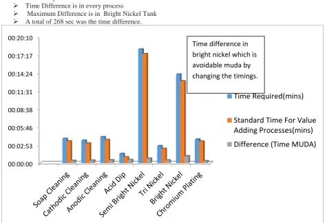
While going through the time study of all the lines in the AEP plant, there were 8 lines out of which 7 lines time was comparable to standard time but on one line there was a difference of time in bright nickel tank (fig.2 shows the standard time, actual time and their differences.)
Result of time study-
Time Difference is in every process
Maximum Difference is in Bright Nickel Tank
A total of 268 sec was the time difference.
Figure 2 Comparison of actual time of dip with std. time
00:00:00 00:02:53 00:05:46 00:08:38 00:11:31 00:14:24 00:17:17 00:20:10
Time Required(mins)
Standard Time For Value
Adding Processes(mins)
Difference (Time MUDA)
Calculation in Time Muda In Case Of Bright Nickel of AEP- 7
Time wastage/ flight bar - 67 sec
Transporter speed delay 20% - 54 sec
The total time required for an individual Flightbars - 5076 sec~ (1 hr 25 min) Thus, from the unity rule,
Time Muda for a Flight Bar in Process Having a Cycle Time of 282 sec (4.9mins) = ~ 3 sec Now,
Average Flight Bars/ day - 196
Time savings/ day - 196x3= 588 sec ~ 10 Flightbars
CHAPTER 7
PDI DATA ANALYSIS (PRE DESPATCH INSPECTION)
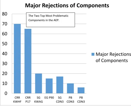
While analyzing the PDI data, two products named CRR KWHF and CRR P17 were the products where the maximum proportion of defects was occurring. These products were making almost more than 50% of the total defects ( fig 3 shows the rejections of components in PDI) So by using 80:20 approach these are the products which are to be analyzed first.
Figure 3 Rejections in PDI
0
10
20
30
40
50
60
70
80
CRR
KWHF
CRR
P17
SG
KWAG
EG P90
SG
CDN3
PB
CDN3
PB
CDN3
Major Rejections of Components
Major Rejections
of Components
Impact Factor 2.675
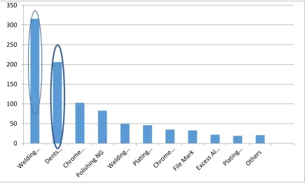
DEFECTS STUDY Defects study of CRR P17
Fig 4Defects Study of CRR P17
Figure 5 Defects Study of CRR kwhf
Conclusion of graphs: In the first graph major defective components are identified and in the Fig4 and Fig5 the defects having major proportion in these products are identified, so that to identify major proportion of PDI defects.
So spatter and dents are major defects.
0 50 100 150 200 250 300 350
To find the probable causes for spatter Reasons for spatter:
Low Voltage
Oil or dust on welding surface
Welding environment
Shielding Gas
No Metal to metal contact
Welding Speed
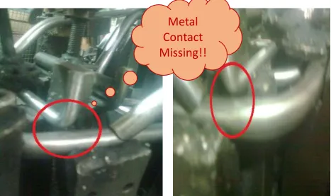
Observation in welding plant:While observing the welding parameters like voltage and current, both these parameters are found to be comparable to standard current and voltage also the proper supplies of shielding gas were there. But the metal to metal contact was missing as shown in the fig6.
Figure 6 Gaps in welding fixtures
TO FIND THE PROBABLE CAUSE FOR DENTS Reasons for dents:
Material handling
Lacking Of Standard Trolleys
Hammering to Fit The Work piece in Gauge
Not proper polishing after Welding
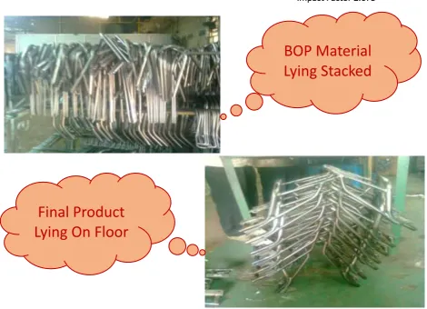
Observation at supplier end: Over loading in the trolleys and storage of material on floor.(As shown in the fig7.)
Metal
Impact Factor 2.675
Figure 7 Over loading of material and poor material handling
CHAPTER 8
CASE STUDY
A case study for the CDN 3 saree guard: A lot of fifty pieces is checked for production, polishing and plating defects alternately (Fig8 shows production defects, Fig9 shows polishing defect, Fig 10 shows plating defects).
Production defects
BOP Material
Lying Stacked
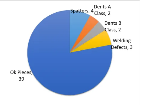
Figure 8 Production defects for CDN 3
Total pieces-50 Ok pieces-39 Spatters-4 Dent A-2 Dent B-2
Welding defects-3
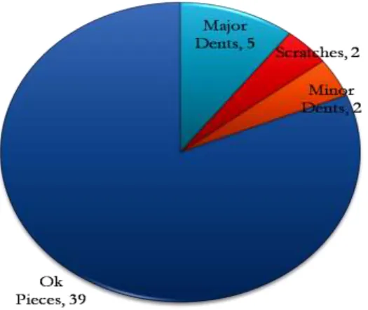
Similarly for plating defects and polishing defects 50 pieces are studied PLATING DEFECTS
Spatters, 4
Dents A
Class, 2
Dents B
Class, 2
Welding
Defects, 3
Impact Factor 2.675
Figure 9 Plating defects for CDN 3
POLISHING DEFECTS
Figure 10 Polishing defects for CDN 3
Analysis of Ishikawa Diagram:
CHAPTER 9
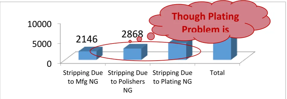
9.1 STRRIPPING DATA ANALYSIS:
Stripping process is used for customer’s rejection for rework. Material which is rejected by customer is stripped (means plating is removed by the use of thinner). This saves the material cost for the company (fig 11 shows the stripping data 17 days).
After that analysis of various defects is done and on the basis of that plating defect comes to be the major defect (as shown in fig 12).But polishing faults is stricken first as it beings an avoidable muda (Fig 12 & 13 shows the polishing defects).
Impact Factor 2.675
Figure 11 Stripping defect analysis
Figure 12 Analysis of trending
DAY WISE POLISHING DATA ANALYSIS:
Analysis Of The Trending
0
5000
10000
Stripping Due
to Mfg NG
Stripping Due
to Polishers
NG
Stripping Due
to Plating NG
Total
2146
2868
4272
9286
Figure 13 day wise polishing faults
Figure 14 product wise faults
REASONS FOR POLISHING FAULTS IN THE MAJOR DEFECTS OCCURING COMPONENTS: 1. Improper material handling
2. Lack of standard Trolleys 3. Improper light.
0 50 100 150 200 250 300 01 -J an 02 -J an 03 -J an 04 -J an 05 -J an 06 -J an 07 -J an 08 -J an 09 -J an 10 -J an 11 -J an 12 -J an 13 -J an 14 -J an 15 -J an 16 -J an 17 -J an Rusty Dents lustre Carbon
Product Wise Study Of Defects
Impact Factor 2.675
Figure 15condition at supplier end
FISHBONE DIAGRAM
Improper
Material
A Day Scene
At the
ISHIKAWA DIAGRAM
Machine
Material
Method
MAN
AESTHET
ICS
Poor
Inspection
Improper
Heating
Process
Non-Std Trolleys
Improper Material
Handling
Rusty Material
Unskilled Labour
CHAPTER 10
PRODUCTIVITY INCREASE:
Using a machine below its capacity and also the above its capacity both includes in muda. Each line in this AEP plant is designed to do a plating of 300 dm2 for each hanger loaded. But the full capacity is not utilized. For this idea of improvement in hangers was suggested which also increased the plating capacity.
Before After Figure 16 Modification in hanger
Analysis Of Ishikawa
Diagram
Impact Factor 2.675
Figure 17 & 18 modified hanger Increase In dm² By This Combination Plating:
• Area of P muffler is 120 dm²/f bars.
• In the place of that 120 dm² we are going to use 240 dm² /f bar.
Figure 9 & 10 combination plating in gear shifter
CONCLUSION
Nothing is perfect but there is always a scope for improvements. Same with manufacturing processes, there is always a scope for improvements.
The tools and techniques used here like cause and effect diagram and 80:20 approach are universal as they have their application not in this AEP but can be applied in almost every manufacturing process.
In AEP, it has helped in identifying major causes of wastes thereby process of elimination can be initiated after going for root cause analysis.
Further, validation can be performed on steps taken for elimination of wastes and results.
Before
Engine guard
CDN
Now with
P.Muffler
which also
saves a
manpower!
REFERENCES
[1] http://www.sharrettsplating.com/electroplating-benefits.html Accessed on 18 November 2014. [2] http://leanmanufacturingtools.org/71/muda-mura-and-muri-lean-manufacturing-wastes/ accessed on 18
November 2014.
[3] http://nzic.org.nz/ChemProcesses/metals/8G.pdf Written by Ken Osborne, Metal Protection Ltd, Auckland, with editing by John Packer.
[4] http://en.wikipedia.org/wiki/Electroplating accessed on 17 November 2014 accessed on 15 November 2014.
[5] Metal Finishing Guidebook And Directory Issue ’93k, Volume 91, Issue 1A, Elsevier Science Publishing Company, Inc., New York, NY, January 1993.
[6] Boulanger, Clotildein. "Thermoelectric material electroplating: a historical review."Journal of electronic
![Table 1 Features of auto electro plating [1]](https://thumb-us.123doks.com/thumbv2/123dok_us/8683523.1734059/1.595.71.531.440.766/table-features-auto-electro-plating.webp)
![Figure 1The seven type of wastes [2]](https://thumb-us.123doks.com/thumbv2/123dok_us/8683523.1734059/3.595.76.523.72.583/figure-the-seven-type-of-wastes.webp)