NUMERICAL SIMULATION OF 3D
KIRLOSKER TV-1 MODEL ENGINE
CYLINDER FOR COLD FLOW
S. SIVA1
Assistant Professor, Department of Mechanical Engineering, SKP Institute of Technology Tiruvanamalai, Tamilnadu-606611, India
Dr.M.SUBRAMANIAN2
Professor, Department of Automobile Engineering, Hindustan Institute of Technology and Science Padur, Chennai, India
K.SIVANESAN3
Assistant Professor, Department of Mechanical Engineering, SKP Institute of Technology Tiruvanamalai, Tamilnadu-606611, India
[email protected] Abstract :
The definition of an efficient optimization methodology for internal combustion engine design using computational fluid dynamic simulation models is presented. This paper aims at validating the fundamental numerical and computational fluid dynamic aspects which can lead to the definition of following models. The models used for analysis of Standard k-ε model, Realizable k-ε model, V2F k-ε model, AKN k-ε model, and Standard k-ω (Wilcox) model. For these reasons, both single-and multi-objective problems will be addressed, where the former are still of relevant interest (i.e. optimization of engine performances), while the later have a much wider range of applications and are often characterized by conflicting objectives.Modeling of the KIRLOSKER OIL ENGINE TV1 will be done using GAMBIT. Flow inside the engine is to be the analysis and validation various turbulence models using STARCD. This is used to find the model which predicts the engine performance better.
Keywords: Cold flow; Turbulence models; Pressure coefficient; Temperature coefficient. 1. Introduction
Experimental studies are more expensive than computational studies. Also using computational techniques allows one to obtain all the required data for the cylinder, some of which could not be measured. In this study, KIRLOSKER OIL ENGINE TV1 engine will be model. Fluid motion and combustion process will be investigated numerically CFD plays an important role in determining how turbulence happening inside a reciprocating engine cylinder during suction, compression, and combustion and exhaust process. These processes have a major influence in engine efficiency and power output. Using CFD these processes can be improved extensively. In order to find optimum condition, it is essential to obtain a good approximation of in cylinder turbulence. One of the major challenges in CFD is that several models need to be combined in order to simulate a complete engine cycle. Among these models k-ε turbulence is the most commonly used turbulence in CFD. For doing the simulation work we will use the STAR CD software.
The KIVA code has been modified to include the Reynolds stress turbulence model (RSTM) by SatpreetNandaet al. [1]. In this study the existing RSTM in the KIVA code has been modified to resolve the flow better in the engine. The flow inside the engine has high bulk velocities in the vertical plane and the flow in the horizontal plane is slow and influenced by shear and pressure effects. K. Anandaveluet al.[3] Improved study flow diesel fuel with eucalyptus oil and experimentally determines their effects on the engine performance, combustion and exhaust emissions such as brake specific energy consumption (BSEC), brake thermal efficiency (BTE), heat release rate, cylinder pressure and emissions. P.N. Shriraoet al. [2] used MAT LAB software has been used to simulate the combustion characteristics of direct injection diesel engine. The result shows increase in the brake thermal efficiency and decrease in the specific fuel consumption for LHR engine
2. Numerical Methodologies
3. Grid Generations
The grids can be classified in to two type’s unstructured and structured grids. Each structured block of coordinate transformation into a cube or square in two dimensional. Most practical flow configuration is obtained using block structured meshes. Arbitrary geometry can be meshed better using unstructured meshes. However, at the cost of same penalties for this flexibility, both in terms of solution algorithms. Generating grid and plots for these meshes are also very complex.
Structured grids are of two types, either Cartesian grid; the grid lines are always parallel to the co-ordinate axis. In curvilinear grids the co-co-ordinate surfaces are curved to fit boundaries. Alternatively grid can be divided into orthogonal and non-orthogonal grids. All grid lines cross at 90˚ for orthogonal grids. For this problem 0.27 million cells 0.79 million faces and 0.29 million vertices are used and showed in fig. 1 then the sectional view of grid is shown in fig. 2.
5. Cold Flow Simulations
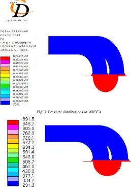
The cold flow simulation is carried out with various turbulence models under adiabatic wall boundary condition. Thus, the results are quantified according to the basic adiabatic relations. The pressure distribution and temperature distribution contours of the cold flow simulations for Standard k-ω (Wilcox) model are shown in the given below Fig. 3 and Fig. 4. It clearly explains about the pressure and temperature distribution inside the cylinder during cold flow simulation and combustion simulation during engine running with conventional mode.
Fig. 3. Pressure distributions at 3600 CA
Fig. 4. Temperature distributions at 3600 CA
Table 1. Comparison of simulated and calculated pressure and temperature values
Variable Simulated Calculated Error (%)
Pressure (bar) 52.14 54.98 5.16
Temperature (K) 871.5 920.6 5.33
6. Combustion Simulation of Biodiesel HCCI Model
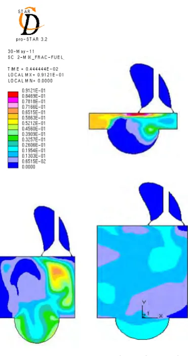
Fig. 5. In-Cylinder fuel fractions at 400CA, 900 CA, 1800 CA
The mixture formation process can be performed inside the cylinder or externally. In the direct injection process the limited amount of time is available for the charge to mix, it depends on engine speed which limits the degree of homogeneity. With respect to the experimental setup where the fuel is vaporised using a fuel vaporiser in the intake system, the fuel input to the CFD model is given in the vapour form which is injected directly in the intake port during suction stroke at 5°CA and stopped at 163.5°CA. When compared to the conventional mode, it is evident from fig. 5 that the fuel is more evenly distributed throughout the cylinder before the compression process is started.
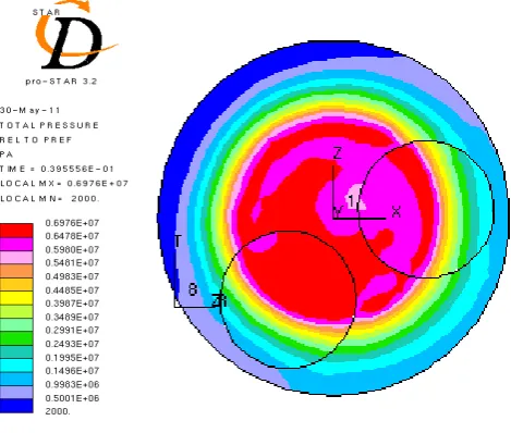
Fig. 7. Pressure distribution at 3600 CA for 75% load
Fig. 8. Pressure distribution at 3700 CA for 75% load
From the above pressure contours it is clearly indicates the pressure distributions inside the cylinder during ignition starting period, peak pressure period and after peak pressure occurrence at 75% load.
7. Validations
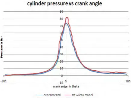
Fig. 9. In-cylinder Pressure comparisons at 75% load
Table 2. Comparison of simulated and experimental pressure values for Standard k-ω (Wilcox)
Variable Simulated Calculated Error (%)
Pressure (bar) 82 72.11 9.86
Conclusion
The cold flow simulation is carried out with various turbulence models under adiabatic wall boundary condition.The pressure distribution and temperature distribution and contours of the cold flow simulations for Standard k-ω (Wilcox) model is nicely match with the experimental results.
Reference
[1] Anandavelu, K; Alagumurthi, N; Saravannan, C. G.(2011) “Experimental Investigation of Using Eucalyptus Oil and Diesel Fuel
Blends in Kirloskar TV1 Direct Injection Diesel Engine”, MRK Institute of Technology, India. Journal of Sustainable Energy & Environment.
[2] Benny Paul; Ganesan, V.(2010) “Flow field development in a direct injection diesel engine with different manifolds”, Indian Institute
of Technology Madras, Chennai, International Journal of Engineering, Science and Technology Vol. 2, No. 1.
[3] NureddinDinler; NuriYucel.(2007) “Numerical Simulation of Flow and Combustion in an Axisymmetric Internal Combustion
Engine”, World Academy of Science & Engineering and Technology.
[4] Satpreet Nanda; Yang, S. L. (2003) “IC Engine Flow Simulation Using Kiva Code And A Modified Reynolds Stress Turbulence
Model”, Michigan Technological University Houghton, Michigan.
[5] Shrirao, P. N; Pawar, A. N.(2011) “Performance Evaluation of Single cylinder Diesel Engine with Mullite as Thermal Barrier Coating
and its Validation using Mat lab”.J.D College of Engineering and Technology, Yavatmal, INDIA. International Journal of Emerging trends in Engineering and Development. Issue1, Vol. 3.
[6] Zhao Zhang.(2007) “Evaluation of Various Turbulence Models in Predicting Airflow and Turbulence in Enclosed Environments by