©2013 JNAS Journal-2013-2-8/289-295 ISSN 2322-5149 ©2013 JNAS
Analysis And Decrease of Electromagnetic
Interference In Diode Bridge Rectifier
Ehsan Hosseini
School of Railway Engineering, Iran University of Science & Technology, IUST, Tehran, Iran
Corresponding author:Ehsan Hosseini
ABSTRACT: Electromagnetic Interference (EMI) refers to the undesired radiated or conducted energy in
some type of electrical systems. Semiconductors are applied in power electronic converters to increase efficiency (Mohan, Undeland and Robbins, 2003).But switching leads to generation of interference over a wide range of frequency and causes radio frequency interference (10KHz to 30MHz). EMI is an inevitable problem in modern power electronic circuits. Modeling and simulation of EMI is the first step in EMC evaluation to help power electronics designers get an estimate on the status of EMC in their designs. Modeling and simulation of diode bridge rectifier are studied in this paper from the EMC point of view. Simulation results demonstrated noncompliance behavior of this rectifier in terms of EMC standards. At the end, by using suitable filters, we can preclude or minimize any undesired effects to meet the standards of acceptable conditions.
Keywords: Electromagnetic interference, LISN, Differential Mode, Common Mode, EMI filter, conducted emissions.
INTRODUCTION
Semiconductor devices, though, help reduce weight and volume of equipments; they can cause some unwanted effects such as Radio Frequency Interference (RFI) emission (Moy, 1989). EMC regulatory Compliance is a problem for manufacturers to bring their products to the market cost-effectively. Post-development modifications would be too costly; therefore it is important consider EMC standards prior to the design phase (Nave , 1986). Modeling and simulation is the most cost-effective way to analyze EMC considerations before developing the products. Most of the previous studies concerned the low frequency analysis of power electronics components (Henderson and Rose, 1994), (Kasikci, 2000). However, different types of power electronics converters are capable to be considered as EMI sources. They could propagate the EMI in both radiated and conducted forms. Line Impedance Stabilization Network (LISN) is required to measure and calculate the interference level (Nave, 1985). Interference spectrum measurement at the output of LISN will be introduced as the criteria of EMC evaluation (Williams, 2001), (Keisier, 1987).
National or international regulations are the references to the evaluation of equipments from the EMC point of view (Williams, 2001), (Keisier, 1987). This paper studies the interference spectrum and its reduction in the radio frequencies range. The simulation of a typical single-phase and three-phase diode rectifier was carried out using equivalent circuit approach with ORCAD9.2 software, bothwith and without EMI filters. The simulation results have been compared with the regulatory limitations indicating noncompliance behavior of power electronic converters from EMC point of view.
SOURCE, PATH AND VICTIM OF EMI
290
elements, source lines and cabling provide paths for conducted noise or interference. Electromagnetic conducted interference has two components: differential mode and common mode (Fluke, 1991).
Differential mode conducted interference
This mode is related to the noise imposed on different lines of a test circuit by a noise source. Deduced current path is shown in Figure 1 (Fluke, 1991). The interference source, path impedances, differential mode current and load impedance are also shown in Figure 1.
Zcir
ZRTN Chassis
Zload Idm
Vdm
Figure 1. Differential mode conducted interference path
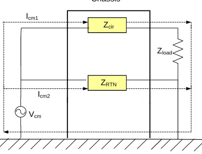
Common mode conducted interference
Noise or interference could appear and be imposed between the lines, cables or connections and common ground that is called common-mode interference. Any leakage current between load and common ground could be modeled by interference voltage source. Figure2 demonstrates the common mode interference source, currents, Icm1 , Icm2 and the related current paths (Fluke, 1991). The power electronic converters perform as the noise source
between lines of the supply network.
Zcir
ZRTN
Chassis
Zload
Icm1
Vcm
Icm2
Figure 2. Common mode conducted interference paths
ELECTROMAGNETIC COMPATIBILITY REGULATION
Electrical equipments especially static power electronic converters are being used more and more these days. As mentioned before, power electronics converters are considered as a significant source of electromagnetic interference and have corrupting effects on the electric networks (Moy, 1989). High levels of pollution reduce the quality of power resulting from various disturbances in electric networks. Some of the residential, commercial and especially medical consumers, on the other hand, are so sensitive to power system disturbances including voltage and frequency variations. The best solution to reduce corruption and improve power quality is to assure compliance with the national or international EMC regulations.
291
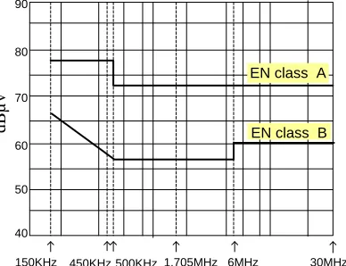
limited frequency ranges of IEC and VDE are different. They range from 150 kHz to 30 MHz and from 10 kHz to 30 MHz in IEC and VDE, respectively. Conforming to regulations is evaluated through comparing the calculated conducted interference level in the mentioned frequency range with the stated requirements in EMC regulations. In united European community, compliance with regulations is mandatory and products must have certified labels to confirm the fulfillment of requirements (Keisier, 1987).
90
80
70
60
50
40
d
B
µ
v
150KHz 450KHz 500KHz 1.705MHz 6MHz 30MHz
EN class A
EN class B
Figure 3. IEC conducted emission limits
Figure4. VDE conducted emission limits
ELECTROMAGNETIC CONDUCTED INTERFERENCE MEASUREMENT Line Impedance Stabilization Network (LISN)
LISN is an industrial element offered by standards to be placed between the supply and power electronics converter including load as an interface to make the measurement of conducted interference possible (Williams, 2001). The stated situation is shown in Figure 5 (Nave, 1985). LISN should have the following characteristics to satisfy measurement conditions (Nave, 1985). 1-Providing a low impedance path to transfer power from source to power electronics converter and load. 2-Providing a low impedance path from interference source, (diode bridge rectifier in here), to measurement port.
AC LISN
Converter
Source Load
Figure 5. LISN placement to measure conducted interference
Class A
292
LISN topology
The common topology for LISN is shown in Figure 6 (Williams, 2001). LISN elements quantity based on the common topology are classified as shown in Table I (Williams, 2001).
R3 C3
R2 C2
R1 C1
L2 L1
Power supply EUT
Figure 6. LISN common topology
Table 1. LISN Elements Quantity
L1 L2 C1 C2
50μH 250μH 250nF 8 μF
C3 R1 R2 R3
4 μF 50Ω 5 Ω 10 Ω
Variation of the signal level versus frequency at the LISN output is the interference spectrum. The electromagnetic compatibility of a device can be evaluated by comparison of its interference spectrum with the standard limitations. The level of signal at the output of LISN in the frequency range of 10 kHz up to 30 MHz or 150 kHz up to 30 MHz is criteria of compatibility and should meet the standard limitations. In practice, the LISN output is connected to a spectrum analyzer and interference measurement is carried out. But for modeling and simulation purposes, the LISN output spectrum must be calculated using appropriate software.
SIMULATION OF EMI DUE TO DIODE RECTIFIER
Orcad 9.2 is the verified and conventional software for electrical and electronic circuits simulations. This software is used to analyze and calculate the conducted interference spectrum in this study. Non-ideal behavior of resistors, capacitors and inductors are taken into account in the simulations. The simulation results are presented in the following sections.
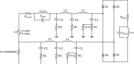
Single Phase Diode Rectifier EMI Simulation
The single-phase diode bridge rectifiers have industrial applications. Sample of such equipment including source, LISN, converter and load in accordance with the block placement of Figure 5. is shown in Figure 7. Common and typical parameters of the simulated circuit are presented in Table 2. and Figure8 illustrates the simulation results, which is the variation of V(R1) at LISN output versus frequency.
Rsource
R3
R=1000000MΩ
CparA
C3 C2
Lsource L2 L1
AC
D3 D1
D2 D4
R2 R1
C1
R=1k
R3
C3 C2
L2 L1
R2 R1
C1
R=1k
Rload
CparLLload
V=220v F=50hz
293 Figure 8. EMI simulation results of a Single-phase diode bridge rectifiers
Table 2. Typical Quantity for simulation elements 220V input voltage 2pF
parL
C
50Hz Frequency
1mΩ
sourceA
R
10mΩ load
R
100nH source
L
50mH load
L
2pF parA
C
Converting the results to dBµv makes it possible to compare them with standard requirements. It is seen in this sample that the level of conducted interference due to converter is not tolerable according to the regulations in Figure 3 and Figure 4. The maximum amplitude of conducted interference in rectifier is 39.177mv which is equal to 91.86dBμv. As a consequence this converter with the mentioned parameters does not comply with the regulations. It is possible to repeat the simulation with the other parameters. the performance may improve with just a few of them, but for the rest the results may become worse.
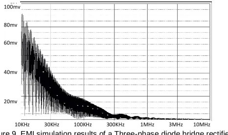
Three-phase Diode Bridge rectifiers EMI simulation
Figure 9. EMI simulation results of a Three-phase diode bridge rectifiers
The maximum amplitude of conducted interference in three-phase diode bridge rectifier is 91.18mv which is equal to 99.198dBμv. As a consequence this converter with the mentioned parameters does not conform to the regulations.
SIMULATION OF EMI DUE TO DIODE RECTIFIER WITH EMI FILTER Filtering Overview
The purpose of the EMI filter is to prevent the undesired electromagnetic energy from entering or exiting from the equipment, however, not without expense. This method uses EMI correcting filters that can be purchased in IC form or can be constructed via discrete components(by using a capacitor or inductor placed appropriately). EMI filters are single-section filters or several single-section filters cascaded together for more attenuation. It has been demonstrated that a two- section filter has less optimum weight than a single-section one; in spite of the fact that
10KHz 30KHz 100KHz 300KHz 1MHz 3MHz 10MHz
10KHz 30KHz 10KHz 300KHz 1MHz 40mv
30mv
20mv
10mv
0v
100mv
80mv
60mv
40mv
294
they both have identical filtering properties in design. The number of sections and configuration are not limited to this presentation. It is important to remember to isolate the input and output cables of the filter.
C O N V E R T E R INPUT P N L IS N LCM LCM LDM LDM CX CY CX CY
Figure 10.Proposed topology of EMI filter
Main harmonic filter should be rated for the switching frequency and its harmonics, i.e. it will absorb all harmonic multiples of the switching frequencies.
Determine filter component values LCM and LDM After determining the filter corner frequency, the filter
component values can be calculated using the equations given below. For CM Noise
) ) 2 ( 2 ( 1
,CM y CM
R C L
f
(1)
CM
leakage to L
L 0.5% 2%
(2) For DM Noise,
) ) 2 ( 2 ( 1
,DM x D
R C L
f
(3)
2 ) ( D leakage
DM L L
L
(4)
These capacitors and inductors are typically within the following values:
Cx = 0.1mF to 2mF
Cy = 2200pF to 33000pF
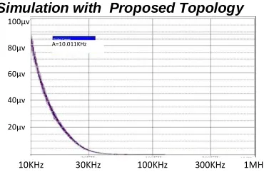
Single Phase Diode Rectifier EMI Simulation with Proposed Topology
Figure 11. EMI simulation results of a Single-phase diode bridge rectifiers with EMI filter
The maximum amplitude of conducted interference in the single-phase diode bridge rectifier is 37.41μv which is equal to 31.46dBμv. As a consequence this converter with the mentioned parameters, attenuates more than 60dBμv and complies whit the regulations.
Three Phase Diode Rectifier EMI Simulation with Proposed Topology
Figure 12. EMI simulation results of a three-phase diode bridge rectifiers with EMI filter
10KHz 30KHz 100KHz 300KHz 1MHz 40µv 30µv 20µv 10µv 100µv 80µv 60µv 40µv 20µv
10KHz 30KHz 100KHz 300KHz 1MHz
295
The maximum amplitude of conducted interference in this rectifier is 88.376μv which is equal to 38.92dBμv. As a consequence this rectifier with the mentioned parameters, attenuates more than 60dBμv and conform to the regulations.
CONCULSION
The appearance of electromagnetic interference due to the operation of diode bridge rectifier is introduced in this paper.Radiated and conducted interference coupling was introduced as the two major types of electromagnetic interference; however only the conducted type was studied in this paper.The Compatibility regulations and techniques of measuring conducted interference were explained. LISN, as an important part of measuring process, and its topology, parameters and impedance were described. Samples of two common power electronic diode rectifiers were considered and their EMI was simulated using orcad 9.2 software.The most important point of this study is that none of the mentioned rectifiers comply with the EMC standard regulations.It is necessary to apply hardware and software mechanisms to reduce the interference to the standard level. with design of suitable EMI filter and simulating the produced circuit, complied with the EMC standard regulations.
REFERENCES
Fluke J C. 1991. Controlling Conducted Emission by Design, Vanhostrand Reinhold.
Henderson R D, Rose P J. 1994. Harmonics and their Effects on Power Quality and Transformers, IEEE Trans. On Ind. App, 1994. pp 528-532. Kasikci I. 2000. A New Method for Power Factor Correction and Harmonic Elimination in Power System, Proceedings of IEEE Ninth
International Conference on Harmonics and Quality of Power, Oct.2000, Vol 3, pp 810 - 815. Keisier B. 1987. Principles of Electromagnetic Compatibility, 3rd edition ARTECH HOUSE.
Mohan N, Undeland T M, Robbins W P. 2003. Power Electronics: Converters, Applications and Design, 3rd edn. Wiley, New York. Moy P. 1989. Automotive Power Electronics: EMC Related Issues for Power Electronics, IEEE, 28-29 Aug. 1989 pp. 46 - 53.
Nave M J. 1986. Prediction of Conducted Interference in Switched Mode Power Supplies, Session 3B, IEEE International Symp on EMC. Nave M J. 1985. Line Impedance Stabilization Networks: Theory and Applications, RFI/EMI Corner, April 1985, pp 54-56.