A LOW COST BEAM STEERING LINEAR ARRAY ANTENNA
FOR SMALL CELL 5G MOBILE NETWORKS
Mohamed Shaik Honnurvali1, Need Nazeema2
1. INTRODUCTION
Millimeter-wave (mmW) technology for V-band (57-66GHz) has become exhilarating opportunities for circuit, antenna, and communication system engineers in next future technology. Crucially, recent improvements in incorporation of antenna and antenna arrays directly on-chip CMOS or in-packing have made the millimeter a low-cost possible technology for the future cellular communications [1]. The latest ITU report statistics showed that the global proportion of people using the internet services have rose to 38.1% of the global population in 2013, up from 23.2% as in 2008 [2].with the advent of new technology and features like multimedia applications and high quality video streaming have lead the service providers into saturation state with the current frequencies spectrum from 700 MHz and 2.6 GHz Globally [3].
To compensate the highlighted issues Millimeter-Wave (mmW) technology could be a promising future which is an unlicensed spectrum with huge available bandwidths in the order of 6-13 GHz. As the wavelength at these frequencies ranges in millimeter by which they face serious attenuation in their RSSI with respect to distance and due to atmospheric absorption and rain attenuation factors. Statistics show that the rain attenuation is 9dB/Km with a rainfall of 25mm/hr (about 1 inch per hour) and faces an atmospheric absorption of 20dB [4]. Future wireless technologies must be validated in the most populated urban environments. In order to enhance capacity and service quality, the cellular network architecture requires to support vast spatial reuse. Massive MIMO base stations (with hundreds or even thousands of antenna) and small-cell AP are two promising approaches for future cellular. Massive MIMO base consumption stations realized with antenna arrays at existing macro base stations, which can exactly concentrate transmitted energy to the mobile users located in such small cells [5]. The patch antenna has been an appropriate choice for linear antenna array design because of its low weight, low profile and lower transmission loss and to attain higher directivity at high frequencies. A Patch antenna is designed and modelled in matlab and simulated results showed a gain around 10 dBi. Further for enhancing the directivity and efficiency of the antenna a linear Patch array antenna has modelled with the designed patch antenna as an element. The modelled system is also fabricated using microstrip technology which is easy to integrate on printed circuit boards. For the fabrication of antenna and antenna array laser machine LPKF and photolithographic process is used.
2. ANTENNA DESIGN AND MODELLING
The antenna comprises of a rectangular patch mounted over RT/duroid 5880 dielectric board with a dielectric constant of 2.33 and a loss tangent of 0.0009. This printed circuit board (PCB) material has some advantages such as low dielectric tolerance and loss, to achieve higher bandwidth it is a better choice for high frequency operation. The width (W) and length (L) of the antenna can be realized by the below equations [6].
2
1
2
r of
c
w
1 Dept. of Telecommunication Engineering, SRM University, Chennai, India.
2 Dept. of Electronics and Communication Engineering, ITS Engineering College, India
DOI: http://dx.doi.org/10.21172/1.131.06
e-ISSN:2278-621X
Abstract- 5G with Millimeter Wave! The most anticipated future technology to be expected in the next decade for wireless communications. Demand for high data rates and large bandwidths and capacity took an insight focus at millimeter wave frequencies. However still several challenges need to be addressed to take live of this proposed system. One of such challenge is design of high gain and directive antenna with beam steering capabilities, In this paper we present designed, simulated and fabricated patch antenna and linear antenna array for V-band. The patch antenna and its linear array design is modeled and simulated in matlab and the results showed that the achieved gain is about 10 dBi with good directivity, and beam steering of ± 250 which can be appropriate model for 5G small cell cellular communications. The fabricated model also showed satisfactory matching results with the modeled and simulated design.
L
f
L
eff o
2
2
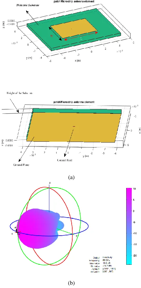
Based on above equations the rectangular patch antenna has a dimension of width (W) 0.40 and length (L) 0.38 and placed at a distance of h mm (substrate thickness) away from the ground plane as shown in figure. 1(a). The 3D Radiation pattern of the designed antenna is shown in figure. 1(b). and gain is observed as 10dBi. The input impedance of the antenna is shown in figure. 1(c). whose resonating frequency is achieved at 61.2GHz. Due to low attenuation, dispersion and easy fabrication process coplanar waveguide feed is chosen for exciting the antenna.
(a)
(c)
Patch antenna Element a) Top and Bottom 3D view. b) 3D Radiation Pattern simulation. c) Input Impedance curve and resonance at 61.2GHz.
3. LINEAR PATCH ANTENNA ARRAY DESIGN
Phased array toolbox has been used in designing linear array of size 4x1with each element as patch antenna which is designed earlier. Same as patch antenna, array is also required to resonate at 60 GHz.The distance between the array elements is an important consideration and it has to be selected accurately so that main lobe of radiation pattern is attained at 60 GHz. The array is series fed to make frequency sensitive and to acquire beam steering over the entire band of interest. The design is shown in figure. 2. the separation between the elements is chose to be 0.25 which projects the main beam direction into the broadside array at 60 GHz [7]. Change in frequency causes the change in electrical length de, which causes a change in phase
of each element byejde , causing the main beam to tilt.
3.1 Linear Patch Array design
It has been observed that decrease in frequency from 60GHz to 57 GHz has caused the main beam to shift to right direction and increase in frequency from 60GHz to 63GHz tilted to left accomplishing the beam steering by just varying the frequency.A beam steering of ±250 was achieved when frequencies are changed in v-band with a step of 1 GHz. The Normalized E Field radiation pattern with beam steering and gain patterns are shown in figure. 3(a). The array resonates at 59 GHz and the maximum radiation is at broadside (00) with a gain of 10dB as shown in figure. 3(b).
(b)
a) Normalized E-Field radiation pattern with beam steering b) Gain Pattern
4. FABRICATION OF PATCH ANTENNA AND LINEAR ARRAY
The equipment’s used for the fabrication of antenna is LPKF protoMat C100HF. The process of fabrication first involves designing the antenna dimensions and layout using Auto cad. These files are required to work on the LPKF photo-laser software that operates the LPKF machine and allows to print the design on the copper-substrate sample. The Laser machine make the contour lines on the substrate for the areas from where the copper is to be removed. The top view of the fabricated patch antenna, and array is shown in Figure 4(a) and 4(b).
(a) (b)
Fabricated prototypes of a) patch antenna and b) linear array antenna.
5. MEASUREMENT OF RADIATION PATTERNS
A block diagram of measurement of E-Field radiation patterns of antenna array at V-band Frequencies configuration is shown in Figure 5. Cascade Microtech system is used to test the antenna and is fed with the 150um pitch GSG probe which is connected to the VNA port 1. To the VNA port 2, an open waveguide WR15 is connected. Both the GSG probe and WR15 are connected using the cables that work up to 67GHz. The linear x-y stages allow the WR15 to scan antenna in x and y directions. The concept of 2D scan includes keeping first y constant and moving WR15 in x direction in steps and capturing all the E-Field values at these points. Then take a step forward in y-direction and repeat the process. By this way with the help of these stage movements, the 2D E-field calculation of antenna are captured in the VNA as S21 parameter. The obtained S21 values from VNA are imported into Matlab. By the help of Matlab routines, E-Field radiation pattern is obtained. The antenna array prototype is fed over a range of 57GHz to 63 GHz, for more clarity and observations.
The absorbers have been used across the probe and around the antenna under test in order to avoid the radiations from the probe and the surrounding elements. The E-Field radiating by the antenna array is been measured in the Near-Field at approximately 40mm from the antenna aperture. The real time measurement setup is shown in Figure 6.
Absorbers around antenna array to avoid spurious radiations,
The antenna array prototype is fed over a range of 57GHz to 63 GHz. The corresponding rectangular E-Field radiation patterns are shown in Figure 7. at phi 00 and 900. It can be seen that by increasing the frequency, the main beam shifts along the theta axis from ±25°.
(a) (b) E-Field Radiation pattern in polar coordinates a) phi = 00 and b) 900
6. OBSERVATIONS AND RESULTS
The Table 1 shows comparison of gain, beam steering angle and average side lobe level measures at different frequencies. The simulated resonant frequency is observed at 61 GHz where the achieved gain is also maximum which 10 dB is. The Side lobe level is observed to be lesser in the range of 61-62 GHz. The bandwidth for element patch antenna is observed to be 5GHz and the antenna array is 6 GHz. This increase in bandwidth was due to different substrates used. The measured values are also very much near with the simulated values. The Table 2 shows a brief comparison of the measured and simulated values of beam steering which is observed to be different. The cause for it was the gap of CPW feed for the array, it should be very thin but the chemical attack from the manufacturing process caused this gap to increase and reduce the feed line. However, this has been verified by performing the simulation of the array with the wider gap and thinner CPW feed line and the result obtained for beam steering are -25° to 10° as obtained with the measured array.
Parameters Comparision
Frequency Gain Angle of Direction SSL (GHz) (dB) (dB)
57 8.72 -250 11 58 8.52 -150 10 59 9.43 -50 10.2
62 9.32 120 7.4 63 8.02 2308.2
64 7.69 250 8.2
Measured And Simulation Comparision
Parameter Measured Simulated
Resonant Frequency 59 GHz 61.2GHz Beam Steering -250 to 250 -250 to 250 Avg side lobe Level ≈9.4 dB ≈8.1dB
7. CONCLUSION
A CPW fed Micro strip patch antenna and series fed antenna array has been designed at mm wave frequencies for Small cell 5G mobile communications [8]. The patch antenna element modelled and fabricated showed a gain of 10 dB with a bandwidth of 5GHz and a 6GHz for the antenna array. The linear array modelled and fabricated showed beam steering about ±250 which can be suitable antenna for small cell 5G cellular networks. Further to achieve higher directivity and beam scanning linear array can be used as feed to dielectric lens or concave lens. By varying the position of the lens as a feed with antenna array resulted in a higher beam steering up to 400. However, incorporation of such antenna with lens might be difficult in real scenarios. Researches are being carried to overcome this risks. The work presented in this paper serves as a valuable contribution to the antenna designers for the design and deployment of millimeter wave based small cell cellular 5G network and other applications such as Indoor location technologies which are expected to emerge across very wide variety of consumer devices over the next years.
8. REFERENCES
[1] Theodore S. Rappaport, Shu Sun, Rimma Mayzus, Hang Zhao, Yaniv Azar, Kevin Wang, George N. Wong, JocelyN K. Schulz, Mathew Samimi, And
Felix Gutierrez, “Millimeter Wave Mobile
[2] International Telecommunication Union (ITU), “Measuring the Information Society Report 2014,” ISBN 978-92-61-15291-8.
[3] Theodore S. Rappaport, James N. Murdock, and Felix Gutierrez, “State of the Art in 60-GHz Integrated Circuits and Systems for Wireless
Communications,” Proceedings of the IEEE. vol. 99, no. 8, pp.1390 - 1436, 2011.
[4] L. X. Cai, X. Shen and J. W. Mark, “Efficient Resource Management for mm Wave WPANs”. Wireless Communications and Networking Conference,
2007.WCNC 2007. IEEE, pp3816 - 3821, 11-15 March 2007.
[5] Z. Gao L. Dai ; D. Mi ; Z. Wang ; M. A. Imran ; M. Z. Shakir, “Mm Wave massive-MIMO-based wireless backhaul for the 5G ultra-dense network”.,
IEEE Wireless Communications Conference, Vol:22, No: 5., pp 13 - 21, October, 2015.
[6] Constantine A.Balanis, “Antenna Theory Analysis and Design”., John Willey & Sons, 2005, NJ: Prentice-Hall, 2005.
[7] R. C. Hansen, Phased Array Antennas, Wiley, New York, 1998.
[8] Volker Jungnickel, Konstantinos Manolakis, Wolfgang Zirwas, Berthold Panzner, Volker Braun, Moritz Lossow, Mikael Sternad, Rikke Apelfröjd,