Multipoint Multimedia Synchronization: A Petri Net Based
Approach
ANIMESHDUTTA1
KONINIKAPAL2
RANJANDASGUPTA3
SWAPANBHATTACHARYA4
12Department of Information Technology
National Institute of Technology Durgapur- 713209, India
3Department of Computer Science & Engineering
National Institute of Technical Teacher’s Training and Research Kolkata-700106, India
4Department of Computer Science & Engineering
Jadavpur University Kolkata-700032, India
12(animeshrec,koninikapal)@gmail.com
3[email protected],4[email protected]
Abstract. Maintaining the satisfactory QoS, synchronization is a big challenge to the researcher in the field of Information and Communication Technology (ICT). In this paper we address a multimedia syn-chronization issue called multipoint synsyn-chronization which is necessary in some distributed collaborative application like teleteaching, teleconferencing etc., involving the play out process of same media stream at different receivers at the same time to achieve fairness among the receivers. We found the incapability of existing petri net to model the above synchronization issue. Some new features are added in existing petri nets to increase its modeling and analyzing power, called self modifying stochastic color petri net (SMSCPN).Then the synchronization issue is modeled with the help of SMSCPN and an generalized algorithm is proposed to achieving multipoint synchronization in IP network. Also some metrics are defined that can measure the performance of the proposed synchronization algorithm.
Keywords: multimedia, multipoint, synchronization, petri nets.
(Received January 4th, 2012 / Accepted September 1st, 2012)
1 Introduction
The real time applications like video conferencing, tele-teaching, telemedicine etc. are increasing day by day, results a drastic change in mode of communication in society and also increase the use of IP network. The real-time distributed multimedia systems are charac-terized by one or several sources transmitting (unicast or multicast) multimedia streams to one or several re-ceivers, playing one or several of the streams at receiver
me-dia packet at receiver side. To maintain the order with temporal relationship between MDUs same as sender side, synchronization among the media packets at re-ceiver side is necessary. Different types of multimedia synchronization are described below.
1.1 Intrastream synchronization
Intra-stream synchronization [10], [1] refers to the tem-poral relationship between the MDUs of one time-dependent media stream. Different buffer control mech-anism [19], [24] are used for achieving such synchro-nization. Suppose a video sequence was captured at a generation rate of 25frames/s i.e. each frame has to be displayed for 40 ms in the visualization device. After reaching at the receiver, the frame will be stored in a reception buffer to guarantee the intra-stream synchro-nization.
1.2 Inter stream synchronization
Interstream synchronization [1] refers to the tempo-ral relationship between the MDUs of different (time-dependent or non-time (time-dependent) media streams. Lip synchronization is a common example of interstream synchronization between the audio stream and the asso-ciated lip movements in video stream [3]. Interstream synchronization can be classified in three ways- point synchronization, real time continuous synchronization and adaptive synchronization [13].
1.3 Multipoint synchronization
Multipoint synchronization [1],[16] refers the playout of media streams to all the receivers at the same time in multicasting scenario to achieve fairness among re-ceivers. We can cite an example of tele-quiz applica-tion where the same video frame is needed to display at same time to all the participating nodes. Other exam-ples of such applications are teleteaching, teleconfer-encing, e-meeting etc. There exist some protocols [4] that are proposed to support such type of application.
In our previous work [18] we have already proposed an algorithm to achieve multipoint synchronization for single media stream and also extended that work in [17] where we proposed an algorithm to achieve mul-tipoint synchronization for specifically one audio and one video stream. In the proposed study we extend our previous work.
1.4 Petri nets
Multimedia systems are very complex. Modeling is re-quired for effective implementation of it. A common
graphical tool used to model concurrent systems is a petri net [26]. To satisfy the requirement to model the system more specifically basic petri net definition is extended in Color petri net(CPN) [9], Dynamic petri net(DPN) [12], Stochastic Petri net [14], Generalized stochastic petri net [15] etc.
1.5 Organization of paper
In this paper, some related research papers is reviewed with their shortcomings in section 2, section 3 presents scope of our work in related research field, the problem statement of multipoint multimedia synchronization is explained formally in section 4. Some metrics are de-fined in section 5, section 6 represents the inter media specification, self modifying stochastic petri net tool is defined in section 7, the multipoint synchronization is-sue is modeledin section 8 and generalized algorithm is given in section 9, section 10 represents the simulation results with discussion and at last conclusion is drawn in section 11.
2 Related works
Instead of defining a new protocol, [22] authors have proposed an extension of RTP/RTCP to provide syn-chronization taking the advantage of feedback capa-bility of RTCP. In this paper group synchronization and inter-stream synchronization was discussed using sender as the Synchronizer Source. Using RTCP RR packet, synchronizer source is able to determine the playout point of the master stream at all the receivers. Authors have proposed swarm synchronization mech-anism in [20] using the PTP and RTP and forward er-ror control mechanism is introduced to prevent packet loss. Synchronization of multimedia stream with multi-ple participants has been addressed in this paper and also in [7]. All the papers discussed above, resolve the synchronization issue by skipping or pausing me-dia stream whenever the asynchrony arises that can lead to important data loss and source control mechanism is used.
have proposed a metric for measuring synchronization error and correction mechanism of synchronization er-ror. But they have not emphasized on the quality of the media.
Confort tool is proposed in paper [16] to achieve multipoint multiple stream synchronization by hy-bridization of TSPN and PNSVS model and use NTP for clock synchronization. A synchronization agency framework comprising of static and mobile agents and synchronization database is described in paper [13]. Adaptive synchronization mechanism is used in this pa-per. An algorithm for multipoint multimedia synchro-nization problems is presented in paper [27]. Effective-ness of algorithm with respect to packet loss is not ex-plicitely measured in all the above works.
Most comprehensive analysis and comparison of the most-known multimedia group and inter-stream syn-chronization approaches are presented in [1]. Several types of multimedia synchronization are identified and a classification of the main synchronization techniques included in most of the analyzed algorithms comple-ments the paper. Finally, a table is presented summariz-ing the main characteristics of each analyzed algorithm according to those techniques and other critical issues.
In [4] authors have proposed a protocol that works between session layer and application layer. Clock syn-chronization algorithm have also proposed using a ref-erence node in distributive manner. But authors have not discussed the synchronization mechanism for mul-tiple streams.
A receiver-based playout scheduling scheme is ex-plained to improve the tradeoff between buffering delay and late loss for real-time voice communication over IP networks in [11]. An important functionality has imple-mented at receiver is the concealment of lost packet but quality of presentation may compromise.
Virtual-time rendering (VTR) algorithm is intro-duced in [25] giving priority more on the intra-stream synchronization quality of voice over the interstream synchronization quality between haptic media and voice. Emphasizing on inter and intra stream nization Virtual timing model is proposed for synchro-nize media stream using virtual clock in [12] and adap-tive buffering scheme for real time multimedia is pro-posed in paper [23]. Multipoint synchronization issue has not been discussed in all these paper for multiple receivers.
Authors have explained the Colored Petri Nets in [8] and designed a simple protocol consisting of a sender transferring a number of data packets to a receiver. They also have presented CPN Tool as an industrial-strength computer tool for constructing and analyzing
CPN models. But CPN cannot model the reactive sce-nario in a system and also time parameter is not em-bedded in CPN. Dynamic Petri Net structure is another extension of basic petri net explained in [21] with con-trol function, concon-trol output arc and dynamic place to model iteration in system and event driven character-istic of system. DPN is used to design a multime-dia orchestration tool with user interaction but it can not model real time scenario. Another extension of CPN is proposed, called SMCPN in [6] for modeling the system that handle user manipulations and network events such as network congestion. Authors have mod-eled self-modifying protocol that can change by the sys-tems while communicating using SMCPN. SMCPN can model the non-determinism without human interven-tion but cannot measure the non deterministic system performance.
3 Scope of works
In the literature review we found a number of authors addressed multipoint synchronization issue for real time multimedia communication. Most of them resolved this synchronization problem by arbitrary skipping pausing in playout of different media streams. As a result the valuable media data (video frame, audio frame etc) may be lost, which leads to degradation of media presenta-tion quality at receiver end.
There are also some algorithms in literature for achieving multipoint synchronization which are cen-tralized in approach that can create a bottleneck for the system in long run.
In this paper we extend our work [18],[17] and try to model the synchronization issue using petri net and find some incapability of existing petri net while ana-lyzing multimedia system model quantitively. So there is a need to extend the existing petri net by introducing some new elements within it. Then we model the syn-chronization issue using newly defined petri net model and analyze it.
We also propose an algorithm that satisfies the distributed approach for multipoint synchronization in multiple streams and also define two metrics that can measure the performance of the synchronization algo-rithm.
4 Formal definition of problem statement
Let there are n number of nodes communicating in mul-ticasting scenario. A node can send up to m number of streams.
Ni represent the ith participating node where
1≤i≤n. R(Ni) represents node Ni is receiver where
1≤i≤n. We take the multicasting scenario,∃Ni ∀Nj
S(Ni)→R(Nj) where 1≤i,j≤n andi�= j. Sixrepresents
xth media stream sent by node N
i where 1≤i≤m and
S(Ni) = true. tix(p) represents time at which pthframe
of Sixstarts transmitting. dijx(p) represents delay
in-troduced in pth frame of S
ix at Njwhere1 ≤ i ≤ m,
S(Ni)= true, R(Nj)= true, 1 ≤ i, j ≤ n andi �= j.
atijx(p) represents arrival time of pth frame of Six at
Nj where 1 ≤ x ≤ m, S(Ni)= true, R(Nj)= true, 1≤ i, j ≤ nandi�= j.
Due to non deterministic delay in IP network, it may happens that ∀x∃p dijx(p)�=dijx(p) that implies ∀x∃p atijx(p)�=atijx(p) [arrival time = transmitting time
+ dealy in network] where S(Ni)= true, R(Nj)= true,
R(Nk)= true and 1 ≤ i, j, k ≤ n, i �= j, i �= k.
ptijx(p) denotes presentation time of pth frame of Six
at Nj where1≤ x ≤ m, S(Ni)= true, R(Nj)= true and 1≤ i, j ≤ n,i�= j.
So we need to find adjijx(p)= the adjusting time(for
skipping or pausing) of pth frame of S
ix at Nj where 1≤ i ≤ m, S(Ni)= true, R(Nj)= true and1≤ i, j ≤ n, i �= j; such that∀p, x, j, k ptijx(p) = ptikx(p) where 1 ≤ i, j, k ≤ n,i �= j,i�= kand S(Ni)= true, R(Ni)=
true, R(Nk)= true.[ ptijx(p)=tix(p)+dijx(p)+adjijx(p),
ptikx(p)=tix(p)+dikx(p)+adjikx(p)]. R is a set that
hold type of relation between MDUs of two different streams. A function rel(Six(p), Siy(p)) maps relation
of pth frame of different stream S
ix and Siy to set R.
If Ni where S(Ni)= true , send more than one stream
then we need to find adjustment time such that ∀ p, x, j, k ptijx(p) = ptikx(p) where 1 ≤ i, j, k ≤ n, i �= j,i �= k, 1≤x≤m and S(Ni)=true, R(Nj)= true,
R(Nk)= true and also ∀p, x, y r(Six(p), Siy(p))→R
holds, where1≤ x, y ≤ mandx�= y.
5 Metric definition
Two metrics are defined here to measure the perfor-mance of the synchronization algorithm with respect to loss of data and asynchrony among receivers.
5.1 Loss metric
Loss metric(Ml) can measure the percentage of loss at receiver end with respect to the MDU received at re-ceiver side.
Loss can be occurred due to network as well as the synchronization process. Let Ri, Nirepresents the
number of packet received and played for ith stream during time t respectively. So,loss metric
Ml =��mi=1(Ri−Ni) m
i=1(Ri) × 100%
5.2 Asynchrony metric
Two types of asynchrony metrics are defined here, rela-tive asynchrony and overall asynchrony.
5.2.1 Relative asynchrony
The playout time difference of each packet for all media streams at one receiver with respect to playout time of the packet to another receiver is defined as the relative asynchrony between two receivers.
Let Pij represents number of packet played out at
receiver side in ithreceiver for jthstream during time t.
Ptij(p) represents playout time of pthpacket at receiver
side in ith receiver for jth stream. Relative asynchrony
between two receivers i,k is measured by the equation
-| �m
i=1 �pij
p=1(Pij(p)− Pkj(p)) �pij
i=1(Pij)
|∀ i,j where 1 ≤
i, k≤ n&i �= k
5.2.2 Overall asynchrony
The playout time difference of each packet for all media streams at all receivers with respect to standard playout time (expected playout time of the packet calculated by some algorithm) of the packet in the system is defined as the overall asynchrony of the system. Standard play-out time of packet p in jth stream for ith receiver is
Pstdij(p). So, overall asynchrony of system is -�
� � ��ni=1
�m i=1
�pij
p=1(P stdij(p)− Pij(p)) �n
i=1 �pij
i=1(Pij)
6 Intermedia specification
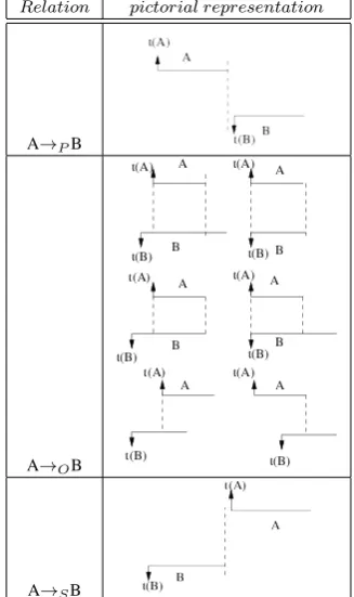
There is well defined temporal relationship between MDUs of continuous media as well as static media of different media streams. The well defined logical rep-resentation within MDUs of inter media is established according to their temporal relationship. The possible relationship of two MDUs may be within two contin-uous media or one contincontin-uous and one static media or both can be static. We define a specification that can represent all possible relationship holds between two MDUs of different media streams. Size of MDU may or may not be same for two different media streams. Three types of relations can hold between MDUs - precedes, succeeds and overlaps. Relations are defined below us-ing two MDUs of different media streams denoted as A and B. ts(A) and d(A) represent the starting time and duration of presentation of frame A.
6.1 A→P B
This relationship holds when A finishes its playout be-fore starting the playout of B. Logical representation of the condition is ts(A) + d(A)≤ts(B).
6.2 A→OB
This relationship holds when A and B satisfy one of the following three conditions.
First condition:
A and B both start and finishes play out at the same time or A starts play out after the starting of B but fin-ishes before the end of play out of B or A starts play out after starting of B but both finish together.
Second condition:
Frame A starts its play out after the start of B but ends after the end of B.
Third condition:
B starts its play out after the start of A but ends after the end of B.
Logical representation of the condition is
(ts(A)= ts(b) && ts(A)+d(A)=ts(B)+d(B)) ||
(ts(A)≥ts(b) && ts(B)+d(B)≥ts(A)) || (ts(A)≤ts(b) &&ts(A)+d(A)≥ts(B)).
6.3 A→SB
This relationship holds if A starts its playout after the end of play out of B. Logical representation of the con-dition is ts(A)≥ts(B) + d(B).
Table 1 represents all posible pictorial representa-tions of intermedia relarepresenta-tionship and corresponding tem-poral relation.
7 Self modifying stochastic color petri net
Self Modifying Stochastic Color Petri Net is proposed as follows:
SMSCPN has 9 tuple {P, T, A,λ, C, I, Tn, F,CL}.
P: {p1, p2,.., px} wherex≥ 0, is a finite set of places.
P = PN U PF where PN is the set of places where no
function is executed in arrival of resource token and PF
is the set of places where some function is executed in arrival of resource token.
T: {t1, t2,..,tm} wherem≥ 0, is a finite set of
tran-sitions. T = TI∪TT andTI∩TT = ∅where, TI is
the set of immediate transitions that fire the token im-mediately when token is available at input place. TT is
the set of timed transitions that take some time to fire tokens from input place to output place.
A:(P × T ) ∪ (T × P) is the finite set of arcs. A = I−∪ I+∪ Ihand (I−∪ I+)∩ Ih=∅where, I−refers
finite set of input arcs and I−⊆(P×T). I+refers finite
Table 1: Intermedia specification.
Relation pictorial representation
A→PB
A→OB
A→SB
set of output arcs and I−= T× P. Ihrefers finite set of
inhibitor arcs i.e. if input place does not hold any token then transition is enabled to fire and a token is produced in output place and Ih⊆P×T.
λ: λ1, λ2, .., λj, wherej≥ 0and j= |TT| is a finite
set of transition rate assigned to timed transition. C: {c1, c2,.., cn} where n ≥0, is a finite sets of
commands.
I: {i1, i2,.., ik} where k≥0, is a finite set of
infor-mations flow through net. Tn :
{(C∗− ε) ∪ P (I)}, is a finite set of token. Tn
= CT∪RT and CT∩RT =∅where, CT = {(C∗− ε)
} is a set of color token. RT = P(I) is a set of resource token.
F: {f1, f2,.., fl} wherel≥ 0is a set of functions that
execute in PF when a resource token is arrived at the
place. Function can generate color token, modify the information in resource token, add new information to resource token i.e. change resource token.
CL: is the finite set of clock.
headed arrow, place, arc and transition created by color token is represented by dashed line.
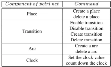
Set of commands with particular sequence repre-sent by the color token. It can change the net structure temporarily to accommodate with new environment and control the flow of resource token. Table 2 represents list of commands execute on different component of petri net in the model.
Table 2: Command executed in SMSCPN.
Component of petri net Command
Place Create a placedelete a place
Transition
Enable transition Disable transition Create transition Delete transition
Arc Create a arc
delete a arc Clock Set the clock value
count down the clock
Transition rules: Let S= {s1, s2,.., sn}wheren ≥ 0, is the set of types of information(I). M: I→S is a function that maps information to a type. Now α: RT→X where X = {S∗− ε}, is a function where∀rt ∈ RT, α(rt) = xwhere x ∈ {S∗ − ε} and if rt= {i
1,
i2,.. i|x|} then x= {M(i1), M(i2),.. M(i|x|)}. β : A →
{S∗−�} is a function that binds arc to a type of resource
token. A resource token can transit through a arc ifβ(x)
=α(rt) wherea∈ Aand rt∈RT.
δ: CT×RT→CL is a function that maps color to-ken combined with resource toto-ken to a clock for timed transition. When clock value goes down to zero, the corresponding resource token transits to output place. When resource token transits from input place, color token that is created at that place is deleted itself and also changes done by color token is removed from net.
8 Multipoint mulimedia synchronization model
In this section we model the scenario where three types of media streams are received at receiver node using the proposed SMSCPN tool. Here we take all possi-ble case of arrival of media streams and show how to process these streams such that multipoint synchroniza-tion is achieved among receivers with interstream syn-chronization at each node. There are some constrains to maintain real time interactive multimedia synchroniza-tion scenario. The maximum tolerable delay for inter-active communications is 250ms [16], refer as primary delay constrain and acceptable asynchrony within audio
video stream is 10ms [16]. In our model control mes-sage is available at receiver side if the maximum delay between sender to all receivers is within primary delay constrain otherwise more QoS support is demanded for that receiver. Reference delay that is used to synchro-nize all receiver, calculated from that maximum delay value in control message. In our model I={audio, video, static media, network delay, time of arrival, duration of presentation, reference delay, generation time, waiting time} and S={a, v, s, d, arr, du, dref, ger, wt}. Different resource token used in this model are of the following types.
x1=(a,d,arr,du); x2=(dref); x3=(x1,x2); x4=(x3,wt); x5=(v, d, arr, du ); x6=(x5,x2); x7=(x5,wt); x8=(x1,x5); x9=(s, d, arr, du); x10=(x9,x2); x11= (x9,wt); x12 = (x1,x9).
8.1 Multipoint synchronization model for multiple media streams
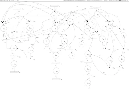
In Figure 1 the model for multipoint synchronization is shown for one audio,video and static media. It con-sists of 25 places and 36 transitions. Here PF = {p2,
p3, p4, p5, p6, p10, p11, p18, p17, p16, p15, p13, p14,
p21, p22, p23, p24} and PN = {p1, p8, p7, p9,p12, p19,
p20, p25}. Transition t1transits at arrival rate of audio
frame receive from internet. Place p1acts as the
receiv-ing buffer. When token is available at p1 and control
message is available at p7then resource token is taken
one by one for processing in place p2. Hence inhibitor
arc is used at transition t2. Function f1executed at place
p2
is-while resource token arrives do
if delay of MDU≤reference delaythen create color token ct1;
else
create color token ct2;
end end
ct1executes the following commands
1. Disable transition t4
2. Enable transition t3
ct2executes the following commands
1. Disable transition t3
2. Enable transition t4
If transition t3 fires then resource token transits to
p3. Function f2executed at p3
is-If transition t4 fires then resource token transits to
p4. Function f3executed at p4
Figure 1: Multipoint synchronization model.
while resource token arrives do calculate waiting time of MDU; Create resource token of type x4; end
while resource token arrives do if delay of MDU≤reference delay+10ms≤250msthen
calculate waiting time of MDU; Create resource token of type x4; else
create color token ct3;
end end
Color token ct3executes the
commands-1. Disable transition t6
2. Create place p8
3. Create transition t9
4. Create arc p4t9, t9p8
When t5 or t6 is fired resource token transits to p5
and p7according to type bound to the arc. Function f4
executed at place p5
is-while resource token arrives do create color token ct4;
end
Color token ct4executes following
commands-1. Set a clock to the transition with information of waiting time associate with resource token.
2. Count down the clock.
After firing of t7token transits to place p6and function
f5executed at p6
is-while resource token arrives do create color token ct5;
end
Color token ct5executes the following
commands-1. Set the clock to transition t8 with fixed value of
2. Count down the clock.
When transition t8is fired then token leaves the net that
means the media frame is played out synchronously at receiver side.
Transition t10 transits at arrival rate of packet
re-ceived from internet. Place p9stores the resource token
coming from network. Now video stream is synchro-nized at multipoint in absence of audio stream other-wise it is synchronize with the audio stream. According to normal transition rule either transition t11or t12fires.
Transition t11is fired if audio is not available at p1and
resource token transit to p10. Function f6 executed at
p10
is-while resource token arrives do
if delay of MDU≤reference delay + 30ms then
calculate waiting time of MDU; Create resource token of type x7; else
create color token ct6;
end end
Color token ct6executes some
commands-1. Disable t13
2. Create place p12
3. Create transition t14
4.Create arc t10p14and t14p12
When transition t14 is fired, the token transits to new
created place p12, that means system demands new
con-trol message for continuing the communication. When t13is fired resource token transits to p13and p7
accord-ing to type bound to the arc. If t12is fired in presence of
audio frame at p1video resource token transit to place
p11 when audio resource token come to place p2 for
processing. Function f7executed at place p11
is-while resource token arrives do
if token holds succedes relation with audio tokenthen
create color token ct10;
else if token holds precedes relation with audio tokenthen
create color token ct8;
else
create color token ct12;
end end
Color token ct8executes some
commands-1. Disable t17and t18
2. Enable t19
Color token ct10execute
commands-1. Disable t19and t17
2. Create place p17
3. Crate arc t18p17
4. Enable t18
Color token ct12executes
commands-1. Disable t19and t18
2. Enable t17
According to the color token created at place p11
tran-sition t19 or t17or t18 is fired and token transit to p18
or p15or p16and p17respectively. At p18function f8is
executed.
while resource token arrives do create color token ct9;
end
Color token ct9executes following
commands-1. Create transition t23and t24.
2. Create an inhibitor arc p2t24 and normal arc
p7t24, p2t23, t24p10, t23p11, p18t24, p18t23.
If t23 is enable then token again compared with next
audio token otherwise t4is enable and token transit to
place p10 and process accordingly. Function f9
exe-cuted at place p17
is-while resource token arrives do create color token ct11;
end
Color token ct11performs following commands
1. Create transition t22
2. Create arc p9t22, t22p11, p17t22.
After firing of t22 token transits to p11. Function f10
executed at p15and p16
is-while resource token arrives do calculate waiting time of MDU; Create resource token of type x7; end
When t13or t20or t21is fired token moves to place
p13. Function f4is executed at that place. After firing
of t15, the token moves to place p14and f11is executed
given below.
while resource token arrives do create color token ct7;
end
Color token ct7executes following
1.Enable transition t25.
2.Set the clock to transition t16with value of frame
duration.
3.Count down the clock.
When t16is fired resource token transit to place p19and
block until t25is enable.
Transition t26is fired if static media data is arrived
from Internet. Place p20 is stored the resource token
coming from network. Now this media data can be syn-chronized at multipoint in absence of audio stream oth-erwise it is synchronized with the audio stream. Tran-sition t27 is fired if token is available at p1. After
oc-currence of t27, resource token transits to p21. f12 is
executed at p21.
while resource token arrives do calculate waiting time of MDU; Create resource token of type x11; end
When t29occurs, token moves to p7and p23
accord-ing to type bound with arc. If t28is fired, resource token
transit to place p22when audio resource token come to
place p2for processing. At p22function f13is executed.
while resource token arrives do
if token holds succedes relation with audio tokenthen
create color token ct13;
else if token holds precedes relation with audio tokenthen
create color token ct15;
else
create color token ct14;
end end
Color token ct13executes following
commands-1.Create transition t32and t33
2.Create a inhibitor arc p2t32and normal arc p2t33,
p7t32, t31p21, t32p22, p22t32, p22t33.
Color token ct14executes few
commands-1.Disable transition t30
2.Enable transition t31
Color token ct15executes few
commands-1.Disable transition t31
2.Enable transition t30
After execution of commands by color token if tran-sition t13is fired the token transit to place p25. At that
place f12is executed. When t29or t35is fired resource
token transits to p23 and f4 is executed. When t34 is
fired, resource token transits to p24and f5is executed at
that place. When t36is fired token leaves the net.
8.2 Probabilistic analysis of the model
Using self modifying stochastic color petri net we can model the stochastic nature of the system. We can re-solve the conflict between two transitions by imposing probability to the transitions. In our model for audio, let token is arrived maintaining the Poisson process at an average rateαthen in time interval t probability that
there is a token in place p1 is PP 1=�∞k=1αe
αt
k! . As
delay in network layer follows the normal distribution with mean and varianceµandσ respectively, control message available at p7 i.e. there is a token at p7 is
PP 7=�dmin250 e
−(x2σ2−µ)2
√
2πσ2 dx. Rate of transition t2is 1 but it is marking dependent. So the probability that there is a token at p2 is same as probability of (PP 1. PP 7).
Then there is a conflict between t3and t4. Now t3 is
enabled when network delay incurred to the token is less than the reference delay. So probability of enabling transition t3is x=�dmindref e
−(x2σ2−µ)2
√
2πσ2 dx. Now transition t4 occurs when delay is larger than ref delay i.e. the
proba-bility of enabling transition t4is y =�dref∞ e
−(x−µ)22σ2
√
2πσ2 dx. So there is a token in p3with probability PP 3= (PP 2.x).
Rate of transition t5is 1, only depend on presence of
to-ken in p3. Similarly the Probability that there is a token
at p4is PP 4= PP 2.y . Here probability of enabling the
transition t6 is z=� dref dref +10
e−
(x−µ)2 2σ2
√
2πσ2 dxand probabil-ity of enabling transition t9 is�dref +10∞ e−
(x−µ)2 2σ2
√
2πσ2 dx.So probability that there is a token at place p5is PP 5=(PP 3
+ PP 4.z). Network delay distribution for particular
source and destination in IP network follows the nor-mal distribution. In our scenario we shape the play out time according to a fixed reference delay for a session (until the reference delay information is changed). So the time for waiting before presentation is also main-tained normal distribution with mean and variable µ1
andσ1 respectively. So the mean time of transition t6
is tt1=�0dref +10−dmine
(x−µ1)2 2σ12
√
2πσ12 xdx. So rate of transi-tion at t6is R1 = PP 5/tt1. So probability of presence of
a token at place p6is PP 6= e−R1t. At place p6token is
blocked for fixed time that equals to the time is taken by an audio MDU to generate at sender side. If generation rate at sender side is R2 then the final rate at which the token is departed i.e. the rate of transition t8is PP 6.R2.
Also taking measure of arrival rate at t1and departure
occurs due to shortage of buffer.
We can analysis the video stream in same manner. For same receiver let token arrives from network at rate β i.e. transition rate of t10 isβ. As arrival
pro-cess of data stream is followed Poisson propro-cess so p9
hold at least one token within t time with probability PP 9=�∞k=1βe
βt
k! . Now transition t11 or t12is fired
de-pending on the resource token available in place p1.
So probability that a token is in place p10 is PP 10 =
PP 9.(1- PP 1).PP 7. Now transition t13 occurs if
de-lay information carried by token is within reference delay addition with 30ms. So probability within this range is a=�dref +30
dmin e−
(x−µ)2 2σ2
√
2πσ2 dxand and t14 is fired with probability b=�dref +30∞ e−
(x−µ)2 2σ2
√
2πσ2 dx.The system is failed with probability PP 10.b. Now t12is fired when
audio master stream available. So probability of en-abling the transition t12 is (PP 1.PP 7.PP 9). For
inter-stream synchronization we do not need any delay in-formation for finding the presentation time of MDU. We only consider the relationship information and de-lay can be in any range. As no token is going to place p12from place p11 probability that a token in place
p13 is PP 13=(PP 10.a + PP 11). likewise audio the time
for waiting before presentation for video is also main-tained normal distribution with mean and variableµ2
andσ2 respectively. The token can block for mean time
tt2=�dref +30−dmin 0
e−
(x−µ2)2 2σ22
√
2πσ22 xdx. So rate of transi-tion t15is R3=(PP 13/tt2). So probability of a token in
place PP 14is e−R3t. If mean and variance of
presenta-tion time isµ3 andσ3 then the mean delay of transition
t16is tt3 =� 30 0
e−
(x−µ3)2 2σ32
√
2πσ32 xdx. So rate of transition t16 is R4 = PP 14/tt3. Probability of presence of a token at
place PP 14is e−R4t. Now transition t25is enabled with
probability of (1- e−R3t) and it is an immediate
transi-tion. So final rate of transition t25 is PP 14(1- e−R3t).
We can measure buffer size from this analysis similarly as audio stream.
We can analyze the static media in same way as we are analyzed the video frame.
9 Algorithm for multipoint synchronization
According to the proposed model for multipoint Syn-chronization two things are considered, maintaining the quality of presentation of media stream with minimum significant data loss in multipoint synchronization pro-cess and using dynamic delay information to synchro-nize the multipoint as mean delay between sender and receivers vary with time.
9.1 Initial and periodic synchronization
For clock synchronization which is done initially and at a regular interval we can use NTP algorithm at the server end, NTP date at receiver end. The NTP service is provided by the network server located at the Inter-net. For resolving the asynchrony between different re-ceivers during the session we use skipping or pausing but not in periodical manner. We only skip the data in the silent part so that we can protect the loss of signifi-cant data.
9.2 Delay and expected playout time calculation
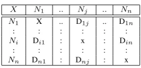
In our algorithm to calculate the expected playout time at receiver end we need two parameters, one is the maximum delay at that moment among all delay be-tween sender and receiver and another is extra mini-mum buffering time use for de-jittering. A delay ma-trix is given in Table 3 store the most updated infor-mation about network delay between all nodes in a sce-nario. The information of delay matrix is used to decide whether a node can able to continue in conferencing scenario or not. If the delay between sender and re-ceiver cross the delay constrain then the rere-ceiver cannot continue with conferencing scenario and should take necessary step for increasing the quality of service in network layer.
Table 3: Delay Matrix.
X N1 .. Nj .. Nn
N1 X .. D1j .. D1n
: : : : : : Ni Di1 : x : Din
: : : : : :
Nn Dn1 : Dnj : x
Consider the scenario of an audio conferencing ses-sion consisting of n nodes, represented by N1, N2, ...,
Nn where any of the n nodes may act as the sender.
For any sender, all the receivers have realized separate amount of network delay that can vary with time and store in delay matrix. Each row of the matrix represents the amount of delay between a sender to all receivers. Dij represents the delay between the sender Ni to
re-ceiver Nj. Whenever the sender sends a data packet,
the entries of the corresponding row is continuously up-dated.
Dimin = min(Dij) for all j=1,2,..n from Ni and
Dimax = max(Dij) for all j=1,2,..n from Ni. We
as-sume the source starts the transmission at time t0.
Net-work delay can cause the receiver to start its play out process as early as t0+Diminor as late as t0+Dimaxthat
causes an initial asynchrony of at most Dimax-Dimin
between each pair of receivers. Letρ be the drift in the playout rate. Let� be the additional time added to allow the initial MDUs of each stream to arrive and be buffered at all receivers. �=(Dimax- Dimin)/(1-ρ)
Then if t0is the time at which the packet is sent, then the
expected playout instant of each of the packet is calcu-lated as Texpected=t0+Dimin+�, where Texpectedis the
time represents the time at which the packet has to be played and reference delay is equals to (Dimin+�).
9.3 Synchronous playout algorithm
Synchronous play out algorithm calculates the time that a frame must wait before presentation and the play-out time of the frame using the expected playplay-out time calculation. Stream that is synchronized at multipoint, known as master stream and streams that is synchro-nized at multipoint according to master stream, known as slave stream and this mechanism of synchronization is called master-slave mechanism. This mechanism is used in our algorithm to achieve multipoint synchro-nization for multimedia in a multicasting scenario. For different streams there is different receiving buffer for receiving the data from Internet. Each receiver follows the Algorithm 1.
A thread is started for each slave stream during exe-cution of Algorithm 1 that process the MDU of slave stream using intermedia specification between them given in Algorithm 2.
All the functions call from Algorithm 1 and Algo-rithm 2 use following notation:
Delay information of audio frame (delay), Time of arrival of audio frame (arr), Reference delay of the system (dref), Time of arrival of video frame (arr),
Waiting time of the frame of master stream (wtm),
Arrival time difference between video frame and corresponding fame of master stream (atd),
Generation time difference of video frame and cor-responding fame of master stream (std),
Duration of video frame (du).
The informations produce from the function is Presentation time(pt) and Playout duration(du).
10 Results and discussion
We took a scenario where three receivers were receiv-ing audio data and mean delay was different for differ-ent receivers. Delay was generated randomly for each packet. We simulated the scenario using our algorithm and also without our algorithm (only each receiver use
while conference is goning on do if audio stream is available then
Select any one of audio stream as master stream.;
Take audio MDU of master stream from buffer ;
process-audio-frame ;
for each different stream available do Start a thread to process MDU of slave stream;
end
else if video stream is available then Select video stream as master stream.; Take video MDU of master stream from buffer;
Call process-video-frame ;
for each different media available do Start threads to process MDU of slave streams;
end else
Select any static media as master stream.; Take MDU of master stream from buffer ; Call process-static-frame ;
for each different media available do Start a thread to process MDU of slave stream;
end end end
Algorithm 1: Synchronous playout algorithm.
the buffer for de-jitter mechanism) and plotted the play-out time against frame number. When presentation time of a frame becomes zero it specifies packet loss. It is clear from Figure 2 that there are seven packet loss in simulation without using our algorithm and presenta-tion time distribupresenta-tion for audio stream is different in different receivers. According to loss metric, for this scenario Ml= 7
60× 100%=11%. It is noticed from
Fig-ure 3 that the presentation time distribution for audio stream in different receivers is merged into one line and there is no loss due to synchronization process while simulating the same scenario with our algorithm.
In scenario1 we took the 1st and 2nd receiver and calculated the relative asynchrony using equation given in section 5. Taking the playout time of frame given by simulation (without using our algorithm) relative asyn-chrony between receiver1 and receiver2 is equals to 52.87ms which is not less than 10 ms whereas using our algorithm it becomes 0.345ms which is almost zero.
Figure 2: Graph for scenario1 without using algorithm.
Figure 3: Graph for scenario1 using algorithm.
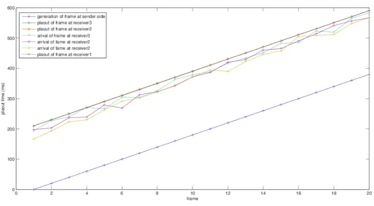
receiving two continuous media (one audio and another video with different frame size) with different mean de-lay for different receivers. Dede-lay is generated randomly for each packet. In Figure 4 the presentation time is plotted against frame number for both receivers. The generation time is also plotted to compare the inter rela-tionship between two media streams. From the Figure 4 we can see the presentation time of two different media
streams at different receiver is same and also the ver-tical difference between two different media streams is same as the generation time which proofs that the syn-chronization process at multipoint does not changes the inter media relationship. In the second scenario, tak-ing the calculated play out time given by simulation we calculate the overall asynchrony using the metric given in section 5. Overall asynchrony value is come in
if MDU precedes MDU of master stream then while MDU precedes MDU of master stream = truedo
if stream is audio then Call process-audio-frame ; else if stream is video then
Call process-video-frame; else
Call process-static-frame ; end
Take next MDU; end
else if MDU overlaps MDU of master stream = truethen
if stream is audio then Call process-audio-slave; else if stream is video then
Call process-video-slave else
Call process-static-slave end
else
return to the buffer end
Algorithm 2: Thread to process MDU of slave stream.
Require: f lag← 0andtemp← 0; diff←(dref-delay);
if diff≥0 and flag=0then
wt← diff;
else if diff≤-10 and flag=0then
wt← 0,f lag← 1,temp← −diff
else if diff≥0 and flag=1then
wt← (temp + diff); else
if (temp+diff)≥0then
wt← (temp + diff); else
if diff≤-10then wt←0, temp←-diff; else
system failed; end
end end
pt←(arr + wt);
Algorithm 3: Process-audio-frame.
lowing manner- 11ms, 2.14 ms, 3.152 ms, 0ms, 6.43ms in 5 consecutive simulation of second scenario. All the value is very close to zero. So we can conclude that our algorithm is succeeded to solve the problem we
ad-diff←(dref-delay); if diff≥0then
wt← diff;
else if diff≤-30then
wt← 0,du← (du − diff); else
system failed; end
pt←(arr + wt);
Algorithm 4: Process-video-frame.
diff←(dref-delay); if diff≥0then
wt← diff; else
wt← 0,du← (du − diff); end
pt←(arr + wt);
Algorithm 5: Process-static-frame.
Require: f lag← 0andtemp← 0; diff←(wtm-std+atd);
if diff≥0 and flag=0then
wt← diff;
else if diff≤-10 and flag=0then
wt← 0,f lag← 1,temp← −diff;
else if diff≥0 and flag=1then wt← (temp + diff); else
if (temp+diff)≥0then
wt← (temp + diff);
else
if diff≤-10then wt←0, temp←-diff; else
wt← 0,du← 0;
end end end
pt←(arr + wt);
Algorithm 6: Process-audio-slave.
dressed.
11 Conclusion
pro-Figure 4: Graph for scenario2.
diff←(wtm-std+atd);
if diff≥0then
wt← diff; else if diff≤-30then
wt← 0,du← (du − diff);
else
wt← 0,du← 0; end
pt←(arr + wt);
Algorithm 7: Process-video-slave.
diff←(wtm-std+atd);
if diff≥0then
wt← diff; else
wt← 0,du← (du − diff); end
pt←(arr + wt);
Algorithm 8: Process-static-slave.
vide the primary delay constrain. So future works can be extend by finding the proper mechanism to provide QoS for live media streaming and incorporating band-width adaptation to fulfill the QoS requirement of user.
References
[1] Boronat, F., Llorat, J., and Garcia, M. Multime-dia group and interstream synchronization
tech-niques: a comparative syudy. Elsevier B.V., In-formation system, 34:108–131, 2009.
[2] Chang, A. Y. An intelligent semantic for design of consistent online smil presentation. In AINA ’05 Proceedings of the 19th International Conference on Advanced Information Networking and Appli-cations, pages 151–156, 2005.
[3] Chang, M. Low-latency lip-synchronized video-conferencing system. In Conference on Human Factorsin Computing Systems (CHI2003), Fort-Lauderdale, FL,USA5(1), pages 465–471, 2003. [4] Dommel, H. and Verma, S. Multipoint
synchro-nization protocol. In Systems, Man and Cyber-netics, 2004 IEEE International Conference, vol-ume 5, pages 4631–4635, 2004.
[5] e. Ramirez, S. E. P. H. L. A. M. R. J. and Gomez, G. R. Logical mapping: an intermedia synchro-nization model for multimedia distributed sys-tem. IEEE Transaction on Multimedia, 3(5):33– 41, Dec 2008.
[6] Guan, S. and Liu, W. Self-modifiable color petri nets for modeling user manipulation and network event handling. IEEE Transaction on Computers, 52(7):920–932, July 2003.
communication. In IEEE GLOBECOM’97, pages 746–752, Nov. 1997.
[8] K. Jensen, L. M. K. and Wells, L. Colored petri nets and cpn tool for modeling and validation of concurrent systems. International Journal on Software Tools for Technology Transfer (STTT), 9(3):213–254, May 2007.
[9] Kristensen, L. M., Jorgensen, J. B., and Jensen, K. Application of color petri nets in system devel-opment. In Verlag B. H. ACPN 2003 and LNCS 3098, pages 626–685, 2004.
[10] Laoutaris, N. Intrastream synchronization for con-tinuous media stream: a survey of playout sched-ulers. IEEE Network, 16(3):30–40, May/June 2002.
[11] Liang, Y. J., Farber, N., and Girod, B. Adap-tive playout scheduling loss concealment for voice communication over ip network. IEEE Transac-tion on Multimedia, 5(4):532–543, Dec. 2003.
[12] Liu, H. and Zerki, M. E. Towards the delay and synchronization control for networked real-time multiobjct multimedia applications. In Proceed-ings of Ninth IEEE International Workshop on Object-Oriented Real-Time Dependable Systems WORDS 2003, pages 79–86, Oct. 2003.
[13] Manvi, S. and Venkataram, P. An agent based synchronization scheme for multimedia applica-tion. Elesvier, The journal of systems and soft-ware, 79:701–713, 2006.
[14] Marco Ajmone Marsan, S. D., Andrea Bobbio. Petri nets in performance analysis: An introduc-tion. In Petri Nets, pages 211–256, 1996.
[15] Marsan, M. A. Stochastic petri net: an elementary introduction. Lecture Notes in Computer Science, 424:1–29, 1990.
[16] Owezarski, P. Enforcing multipoint multimedia synchronization in videoconferencing application. Springer-Verlag B. H., IDMS 2000, LNCS 1905, pages 65–76, 2000.
[17] Pal, K., Upadhyay, P. D., and Dutta, A. A petri nets based model for multipoint multistream syn-chronization in multimedia conferencing. In The second international conference on security en-riched urban computing and smart grid, volume 223, pages 64–73, 2011.
[18] Pal, K., Upadhyay, P. D., and Dutta, A. A petri nets based model for multipoint synchronization in audio conferencing. In Third International Conference on Communication Systems and Net-works, pages 65–76, Jan. 2011.
[19] Qiao, Z., Venkatasubramanian, R. K., Sun, L., and Ifeachor, E. C. A new buffer algorithm for speech quality improvement in voip system. Springer sci-ence business media, LLC, pages 189–206, 2007.
[20] Rautiainen, M., Aska, H., T.Ojala, Hosio, M., Makivirta, A., and Haatainan, N. Swarm synchro-nization for multi-recipent multimedia streaming. In Multimedia and Expo, ICME , IEEE Inter-national Conference, pages 786–789, June/July 2009.
[21] R.Tan and Guan, S. A dynamic petri net model for iterative and interactive distributed multimedia presentation. IEEE Transaction on Multimedia, 7(5), Oct. 2005.
[22] Segui, F. B., Cebollada, J. C. G., and Mauri, J. L. An rtp/ rtcp based approach for multimedia group and inter-stream synchronization. Multime-dia Tools and Applications, 40(2):285–319, 2008.
[23] Xie, Y., Liu, C., Lee, M. J., and Saadawi, T. Adap-tive multimedia synchronization in teleconferenc-ing system. Sprteleconferenc-inger- Verlag, multimedia system, 7:326–337, 1999.
[24] Xu, Y., Chang, Y., and Liu, Z. Calculation and analysis of compensation buffer size in mul-timedia system. IEEE communications letters, 5(8):355–357, Aug. 2001.
[25] Y. Ishibashi, T. K. and Tasaka, S. Inter-stream syn-chronization between haptic media and voice in collaborative virtual environ- ments. In 12th an-nual ACM international conference on Multime-dia, New York, USA, pages 604–611, Oct. 2004.
[26] Yen, H. Introduction to the petri net theory. In Recent Advances in Formal Languages and Ap-plications, volume 25, pages 343–373. Springer, 2006.