Volume 5, Issue 7, July 2016
Abstract- The simulation results of circular tube arrangement with the same minimum flow cross sectional area were used. The factors like different angle , amplitude, longitudinal fin pitch, wavelength and wavy length were examined. The prediction result of average Nusselt number friction factor f and colburn j factor were compared with the experimental correlations [Y. B. Tao, Y. L. He, J. Huang and W. Q. Tao]. The tube outside diameter based on the Reynolds number ranging from 500 to 4000. The mean deviation range for Nusselt number is 1.98% to 4.85% and for friction factor mean deviation range is 1.54%.
The distribution of local Nusselt number and the friction f factor and colburn j factor were studied at wavy angle equal to 5 deg, 10 deg, 15 deg, 17 deg, 18 deg, 22 deg and 24 deg respectively.
The wavy angle can greatly affect the distributions of local Nusselt number , colburn j factor , friction factor f makes the distribution present are fluctuating with respect to the direction of fluid flow. The result shows, with the increase of Reynolds number the effects of wavy angle, effect of wavelength, effect of amplitude, effect of grid independence test on the local Nusselt number are more significant.
Key words- Wavy plate fin and circular tube heat exchanger, CFD, Nusselt number, j and f factor, Pressure drop.
1. Introduction
A heat exchanger is an efficient device for the transfer of energy in the form of heat from one medium to another medium which may or may not be in direct contact with each other. Heat exchanger are used either individually or as components of a large thermal systems in a wide variety of commercial , industrial and household applications examples like power generation, refrigeration, ventilation and air conditioning system, aerospace industries, manufacturing, food processing, chemical and petroleum industries, electronic chip cooling and as well as environmental engineering.
Manuscript received Jul, 2016.
Soujan R, Mechanical Department ,M I T College Mysore, ., (e-mail: [email protected]). Mysore,India, 8147649321 Dr V Shehadri, Mechanical Department, M I T College Mysore Mysore, India.,9482184652 Professor Yogesh kumar K J, Mechanical Department M I T College Mysore Mysore India 9480839634
2. Background
Masoud asadi [6] concluded, the surfaces with wavy patterns are one of the popular surfaces in Plate-fin heat exchanger. Due to the sinusoidal curve of this surface calculating heat transfer area is difficult. In this study, the new method is determine to precise value of heat transfer area is presented. The validation of method is examined by three types of wavy fins in plate-fin heat exchanger. The result shows high level of accuracy in the presented method. The result showed data is presented by Kays and London to calculate total heat transfer area for 11.5-3/8Watts has 9.4% error. While for another surface is acceptable from engineering view. Consequently, this method can be used in the optimization process.
Y B Tao [4] identified, the increase of Re number leads to the increase of Nusselt number and the decrease of the friction factor f. The enhancement of heat transfer is due to the increase of the module product temperature and velocity gradient. The synergy between the velocity and the temperature gradient becomes worse & worse with increase of the Reynolds number, leading to a less increasing tendency of Nu with Re. There exists an optimum fin pitch at which the Nusselt no. is the maximum, but f always decrease with the increase of fin pitch. The avg intersection angle show an asymptotic tendency with the increases of fin pitch, leading to the insensitivity of the Nusselt number with increase of the fin pitch beyond a certain value of the fin pitch.
R Borrajo-Pelaez [13] concluded the increase in Re entails a growth of Nu, therefore the convection heat transfer gains importance and the heat exchangers thermal performances is enhanced. The Nusselt predicted by the air/water side model is slightly lower. Since FC decrease, the mechanical performance is improved gradually. Reducing the distance between fins enhances the thermal performance of heat exchangers, i.e., the Nu increases. There are no significant differences between the results of the air and air-water side model in these cases. Mainly the FC rises intensely when reducing the fin pitch as it generates an obstruction in air flow. And also the mechanical performance decreases. Arafat A Bhuiyan [15] concluded, the effects of the tube arrangement, different geometrical parameters & inlet flow different angle are investigated in terms of heat transfer and pressure drop and the efficiency for the wavy fin and tube heat
exchanger for turbulent flow regime using k-ω(omega) turbulence model with the 5% turbulence intensity. The tube arrangements and the geometrical parameters such as pitch, a wavy angle and a inlet flow angle is strongly effected to the
3D NUMERICAL STUDY OF LOCAL HEAT
TRANSFER COEFFICIENT OF WAVY PLATE FIN
WITH CIRCULAR TUBE HEAT EXCHANGERS
USING CFD
Volume 5, Issue 7, July 2016 flow structure. Comparatively higher heat transfer and
pressure drop is found in a staggered line arrangement than in lined arrangement for both laminar and turbulent case. By increasing Ll and Lt, j and f both decrease as flow become free and very less compact. But fin efficiency goes high mainly. The fin spacing very strongly influences the heat transfers and pressure drops. If it is very small, the effects are very less; if it is too large, the effected is comparatively larger. The higher pressure drop and the heat transfer are observed for the more inclination in a given flow length, but the efficiency decreases with increase in the wavy angles. With the increase in positive flow angle, the effects in the heat transfer and pressure drops is decreased. Again, with a increase in the negative flow angle, the effect in those criteria’s is same. But the decreases for negative flow angle are higher compared to the positive flow angle.
3. CFD METHODOLOGY AND VALIDATION
Methodology is nothing but the step by step course of action with which the CFD codes work. A proper methodology is essential for any practical problem to be solved. Computational fluid dynamics is a computer based simulation method for analyzing fluid flow with heat transfer. It will be advantageous to use CFD, since large amount of result can be produced at virtually no added expense. Parametric studies to optimize equipments are very in-expensive with the CFD when compared to experiment. Numerical analysis of fluid flow and heat transfer problems will require proper methodology for solving the governing equations of motion subject to appropriate boundary condition .In the present study software ANSYS FLUENT- 14 is used for the analysis. It uses finite volume method to solve the equations and it is very important to ensure that the flow domain is descretized properly. The governing equations like conservation of mass, Navier Stroke equations and also the energy equations have to be solved simultaneously. In addition, to the flow is turbulent propers choices of the turbulence model is very important and crucial.
3.1 MODEL DESCRIPTION
FLAT PLATE
The schematic diagram of the flat plate fins circular tubes exchangers is shown in the figure 8 below with two row of tube in the direction of fluid flow. Table 1 lists all the geometric dimensions for this flat plate fin circular tube heat exchanger. The air flow directions in x- direction, fin span wise direction in y-direction and fin thickness directions is z-direction as shown in the different figures below
TABLE 3.1:- Geometric dimensions for the studied wavy plate heat exchanger
Tube row number 2
Tube outside diameter (mm) 10.55
Transverse pitch (mm) 25
Longitudinal pitch (mm) 21.65
Fin pitch (mm) 2.0
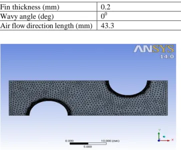
Fin thickness (mm) 0.2
Wavy angle (deg) 00
Air flow direction length (mm) 43.3
Fig 3.1: Schematic of grid systems for flat plate fin with circular tube heat exchanger
Fig- 3.2:- Flat plate fin with circular tube domain with grid systems
BOUNDARY CONDITIONS
TABLE 3.2:- Boundary conditions used for flat plate fin circular tube heat exchanger
Inlet Inlet velocity(3.71m/s), Inlet temperature(278oK)
Outlet Outflow
Wall Wall temperature(333oK) Tube Wall temperature(3330K)
Axis Symmetry
Model is made to import through Fluent after doing mesh convergence test (Grid independent Test).Simulation is made to run with following boundary conditions by giving the temperature of fluid medium as 278degK, and constant wall temperature will be given for the walls and tubes of 333oKelvin.
WAVY PLATE
The schematic diagram of the wavy plate fin circular tube heat exchangers is shown in the figure below with two rows of tube in the flow direction. Table 1 lists all the geometric dimensions for this wavy plate fin circular tube heat exchanger. The air flow directions in x- direction, fin span wise direction in y-direction and fin thickness directions is z-direction as shown in the different figures below
.
Volume 5, Issue 7, July 2016 TABLE 3.3:- Geometric dimensions for the studied wavy
plate heat exchanger
Tube row number 2
Tube outside diameter (mm) 10.55
Transverse pitch (mm) 25
Longitudinal pitch (mm) 21.65
Fin pitch (mm) 2.0
Fin thickness (mm) 0.2
Wavy angle (deg) 170
Wavy length (mm) 10.825
Air flow direction length (mm) 43.3
Fig 3.3: Schematic of grid systems for wavy plate fin with circular tube heat exchanger
Fig- 3.4:- Wavy plate fin with circular tube domain with grid systems
BOUNDARY CONDITIONS
TABLE 3.4:- Boundary conditions used for wavy plate fin circular tube heat exchanger
Inlet Inlet velocity(3.71m/s), Inlet temperature(278oK)
Outlet Outflow
Wall Wall temperature(333oK) Tube Wall temperature(3330K)
Axis Symmetry
Model is made to import through Fluent after doing mesh convergence test (Grid independent Test). Simulation is made to run with following boundary conditions by giving the temperature of fluid medium as 278degK, and constant wall temperature will be given for the walls and tubes of 333o Kelvin.
3.2 Validation of the CFD methodology
The process of validation involves the determination of various factors like extent of Discretization, the choice of turbulence model, criteria of convergence etc .In the present study the methodology has been validated by analyzing the heat transfer to the fluid flowing through a pipe both in laminar and turbulent modes, using 2 different turbulence model k-ε and k-ω SST Standard solutions are available for this particular problem and the computed results are compared with them.
Table 3.5: Variation of predicted Nusselt no with different grid numbers
Mesh Nusselt no (Present Simulation) Nusselt no K- K (Y B Tao) 23.009 25.01 24.8 20000 22.35 23.8 23.7 30000 22.18 23.3 23.2 40000 22.00 23.02 22.9
Fig 3.5:variation of predicted Nusselt number with grid number system
It was observed from the Fig 3.5, that k-ε model gives better results than k-ω model when compared with the results of Y B Tao [4] which is in close agreement. Thus we select k- ε model for our research in further analysis. 4. ANALYSIS OF FLAT AND WAVY PLATE HEAT EXCHANGERS
Fig 4.1:Reynolds no. v/s pressure drop for flat plate and wavy plate fin with different velocities
Volume 5, Issue 7, July 2016
Fig 4.2: Reynolds no. v/s pressure drop for flat plate and wavy plate fin with uniform velocity
For the validation of the numerical approach followed and to select the most suitable model for simulation, the geometry of flat plate fin with circular tube and wavy plate fin with circular tube is maintained same as experimental work. The simulation is carried out for different velocities and different Reynolds number ranging from1000 to 5000 in the mentioned domain is done. The present work is mainly focused on the turbulent regime, from the fig4.1and fig 4.2 it is evident that the k-epsilon model computed most proximate results.
4.1 EFFECT OF UNIFORM VELOCITY FOR WAVY
PLATE FIN WITH VARIOUS TUBEGEOMETRIES
TABLE 4.1: HEAT TRANSFER RESULTS FOR VARIOUS TUBE GEOMETRIES Re no. V H.T co-efficient W/m2-k Circular tube Elliptical tube Flat tube Rectangular tube Circular (Y B Tao) 500 3.71 59.85 57.66 59.12 55.79 60.74 1000 3.71 64.88 61.78 63.49 58.68 67.73 1500 3.71 69.03 65.38 66.93 60.92 72.19 2000 3.71 71.77 69.54 69.52 62.24 70.40 2500 3.71 73.92 72.02 72.48 63.51 72.20 3000 3.71 75.14 72.61 74.16 64.15 75.54 3500 3.71 76.20 73.96 75.68 64.40 78.00 4000 3.71 78.70 75.68 77.69 64.80 79.26
Fig 4.3: Reynolds Number v/s H.T Coefficient for various tube
The above Table 4.2 gives the heat transfer coefficient of the wavy plate fin heat exchangers with different tubes like circular, elliptical, flat and rectangular tubes. Here we concluded that in the wavy plate fin with circular tube have good heat transfer co-efficient results then the wavy plate fin of other various tube geometries. It clearly shows that the
increase of Reynolds no. with same velocity, increase the value of heat transfer co-efficient. The above table values is obtained for a fixed grid generations of 35000 elements.
Fig 4.4 pressure contours for various tubes
Fig 4.5: Temperature contours for various tubes
Fig 4.6: Velocity vector contours for various tubes 5 PARAMETERS STUDY OF WAVY PALTE HEAT EXCHANGER
The software package in ANSYS FLUENT 14 has several turbulence models that could be used for the analysis of wavy plate heat exchangers with circular pin fins. The most widely used model is k-ε model when the flow is fairly well defined. During the present analysis, two models namely k-ε and k-ω model were used. It was observed that k-ε model give better agreement with exact solutions and hence this model has been chosen for all further analysis.
Volume 5, Issue 7, July 2016 The factors like different angle, amplitude, fin pitch,
wavelength wavy length were examined. The predictions results of average Nusselt no (NU) ,Friction factor (f) and
Colburn factor (j) were compared with the experimental correlations.
5.1 Effect of angle
For examining the angle effect on heat transfer and the fluid flow, the simulations were performed under the same parameter conditions as circular tube defined in the physical model, only the angles was varied from 5 to 24 deg and also the Reynolds number is taken from 500 to 4000 with the corresponding inlet velocity is 3.71 m/s. The Nusselt number increases with the increase of angles. The increasing tendency is higher with increase of angles. Because of limited by the geometry parameter of the physical model and the angles varies from 5 to 24 deg.
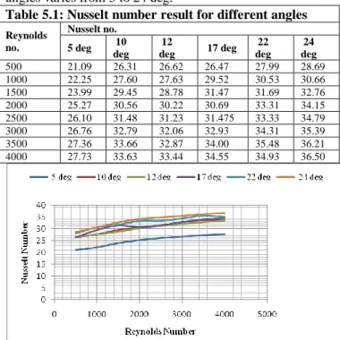
Table 5.1: Nusselt number result for different angles
Reynolds no. Nusselt no. 5 deg 10 deg 12 deg 17 deg 22 deg 24 deg 500 21.09 26.31 26.62 26.47 27.99 28.69 1000 22.25 27.60 27.63 29.52 30.53 30.66 1500 23.99 29.45 28.78 31.47 31.69 32.76 2000 25.27 30.56 30.22 30.69 33.31 34.15 2500 26.10 31.48 31.23 31.475 33.33 34.79 3000 26.76 32.79 32.06 32.93 34.31 35.39 3500 27.36 33.66 32.87 34.00 35.48 36.21 4000 27.73 33.63 33.44 34.55 34.93 36.50
Fig 5.1 Reynolds number v/s Nusselt number
.From the above table 5.2 the different angles like 5deg, 10 deg, 12 deg, 17deg, 22 deg and 24degs heat transfer coefficient results obtained from CFD with different Reynolds number having same velocity of 3.71m/s. It clearly shows that the plate with 24 deg angle gives the better Nusselt values.
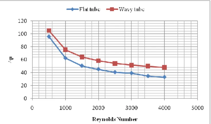
Table 5.2: Pressure drop result for different angles
Reynolds no. Pressure drop 5 deg 10 deg 12
deg 17 deg 22 deg 24 deg
500 94.68 94.82 97.33 107.45 126.12 131.65 1000 64.74 65.71 71.05 75.12 90.52 95.46 1500 54.52 55.99 61.53 62.98 74.94 80.14 2000 49.11 50.30 54.23 57.72 66.42 72.37 2500 45.10 47.90 49.39 53.43 64.07 68.01 3000 41.87 40.28 44.66 50.58 60.87 62.07 3500 39.78 37.48 43.08 48.23 54.95 62.23 4000 37.87 36.33 43.87 50.06 57.96 60.14
Fig 5.2 Reynolds number v/s ∆p
Fig 5.2: Pressure And Temperature Contours For Effect Angle
6 CONCLUSION
The work were we carried out in this project, the k- epsilon method was adopted to generate 3 dimensional computational grids. The air side heat transfer and the fluid flow characteristics of wavy plate fin – circular – tube arrangement were performed by taking into account the grid independency effect, amplitude effect, longitudinal fin pitch and wavelength effect. The simulations results of average Nusselt number, colburn j factor, friction f factor and pressure drop were compared with the experimental correlations and Schmidt approximations, the good agreements validate the model code. The local Nusselt number and temperature distributions on fin surface at different wavy angles like 00 (plain plate fin), 50,100,150 ,170
,
200, 220 and240 were studied. The following conclusions can be made;
1. The average Nusselt number of the wavy plate fin and circular tube heat exchanger increases with the increase of Reynolds number but the friction factor f and colburn j factor decrease.
2. For the 00 (plain plate fin), the local Nusselt number decreases more quickly along the fluid flow direction, at the outlet region ,it is much smaller compared with the values of the inlet region and at the back region of tube, the local Nusselt number has a drastic decrease.
3. For wavy plate fins, the distributions of the local Nusselt number, colburn j factor and friction f factor are more complicated due to the effect of the wavy angle. The local Nusselt number decreases sharply at the inlet region, and then it increases at near to
Volume 5, Issue 7, July 2016 the first wave crest. After the first wave crest, it
decreases sharply again and then it decreases slowly up to the first angle wave trough where the local Nusselt number becomes a relative minimum. At each wave crests and the wave troughs, the trend is almost similar but the only difference is in variation degree. The larger value of the wavy angle, the more distinctness of the phenomenon. We can appropriately increase the fin area and wavy angle at the inlet but decrease the fin area and the wavy angle at the outlet region which could not only enhance the heat transfer but also decrease material consume and pressure drop.
References
1. Y.B.Tao,Y, L, He,Z.G.Wu (2007) :
Three-dimensional numerical study and field synergy principle analysis of wavy fin heat exchangers with elliptic tubes.
2. LitingTian, Yaling He (2009): A comparative study on the air-side performance of wavy fin-and-tube heat exchanger with punched delta winglets in staggered and in-line arrangements.
3. Chi-Chuan Wang, Young-Ming Hwang (2001) : Empirical correlations for heat transfer and flow friction characteristics of herringbone wavy fin-and-tube heat exchangers.
4. Y.B.Tao, Y, L, He (2006) : Numerical study of local heat transfer coefficient and fin efficiency of wavy fin-and-tube heat exchangers.
5. Sreebhash s Kutty and T.P.AshokBabu ISSN print 2319-3182 (2012): CFD study of single phase flow distribution in rectangular, wavy and offset minichannels with water.
6. Masoudasadi, Dr.Raminhaghighkhoshkhoo IJTE VOLUME-1, Issue 1 (2013): Study on heat transfer area of a plate fin heat exchanger with wavy surfaces.
7. Ahmed F khudheyer& Mahmoud Sh Mahmoud ISSN 1819-6608 (2011): Numerical analysis of fin tube plate heat exchanger by using CFD technique. 8. Hajareswapanil, Dr.Kore Sandeep S VOLUME 2
Issue 4 (2013): Experimental investigation of heat transfer enhancement from waveform pin fins. 9. Lucas Engelhardt, Ulm (2014): Flow and heat
transfer in a 3D pin fin channel.
10. Y B Tao, Y L He, J HUANG, Z G Wu, and W Q Tao 1163-1175 (2006): 3D Numerical study of wavy fin and tube heat exchangers and field synergy principle analysis.
11. Anna Margrete Hansen Bjørn H. HjertagerTron Solberg (2008): CFD simulation of a fin-and-tube heat exchanger Heat transfer, fluid flow, and turbulence model analysis using 3D open-source CFD code.
12. R Borrajo-Pelaez, J Orteag-casanvo, J M Cejudo-Lopez (2010): A 3D numerical study & comparison b/w air side model & air/water side model of a plain fin tube heat exchanger.
13. Nasersahiti, Vorgelegt Von (2006): Thermal and fluid dynamics performance of pin fin heat transfer surface.
14. Arafat A Bhuiyan, A K M Sadrulislam, M Ruhul Amin ISSN 2151-8629 (2012) : Numerical study of 3D THERMAL & HYDRAULIC characteristics of wavy fin & tube heat exchanger.
15. Stan islav KNOTEK, Miroslav JICHA (2012): Simulation of flow over a wavy solid surface; comparison of turbulence models.
16. VeliOzbolat, NehirTokgoz, Besirsahin VOLUME 7 No 10 (2013): Flow characteristics & heat transfer enhancement in 2D corrugatedchannels.
17. David T.W. Lin, Ha ThiXuan Chi, Chong-Ching Chang, Cheng-Chi Wang and Chung-Neng Huang,Member, IEEE (2010):The optimal design process of the plate heat exchanger.
18. Dr. B Sreedarrao, M Mayuri, D Krishnakanth, Himanshu V, Dr.Muralikrishna VOLUME 6 Issue 11 (2015): Heat transfer studies in wavy corrugated plate heat exchangers.