http://www.sciencepublishinggroup.com/j/ajnc doi: 10.11648/j.ajnc.202009012.11
ISSN: 2326-893X (Print); ISSN: 2326-8964 (Online)
Delay Sensitive Protocol for High Availability LTE
Handovers
Vincent Omollo Nyangaresi, Silvance Onyango Abeka, Anthony Joachim Rodrigues
School of Informatics & Innovative Systems, Jaramogi Oginga Odinga University of Science & Technology, Bondo, Kenya
Email address:
To cite this article:
Vincent Omollo Nyangaresi, Silvance Onyango Abeka, Anthony Joachim Rodrigues. Delay Sensitive Protocol for High Availability LTE Handovers. American Journal of Networks and Communications. Vol. 9, No. 1, 2020, pp. 1-10. doi: 10.11648/j.ajnc.202009012.11
Received: December 30, 2019; Accepted: January 13, 2020; Published: April 1, 2020
Abstract:
Long delays during the handover process lead to dropped calls which deteriorate the network quality of service. In addition, these delays impede the incorporation of authentication during the handover process which exposes the handover process to attacks such as desynchronization, network masquerading and session hijacking. In this paper, a delay sensitive protocol is developed based on the neuro-fuzzy optimization process and tracking area partitioning into no handover region, low probability handover region and high probability handover region that facilitated advance buffering of the figures of merit. The protocol computes the average delays during the handover process such that handovers taking longer durations than the average value are queued in the mobility management entity (MME) buffer and dispatched in a first in first out (FIFO) basis. The conventional permitted duration between handover command and handover execution is between 0.5 seconds and 1.5 seconds. To prevent holding the network resources for long durations, a handover termination duration was set to the lower bound of this conventional permitted duration, which was 0.5 seconds, such that handovers taking longer this duration were explicitly dropped. The reduced delays during the handover process facilitated the incorporation of entities authentication before subscribers can be transferred to the target cell. Simulation results showed the developed protocol greatly reduced handover delays to an average of 0.048 seconds. In addition, the source evolved Node-B (eNB), user equipment (UE) and target eNB were able to authenticate each other to boost security during the handover process.Keywords:
Delay Sensitivity, Neuro-fuzzy, Low Latency, Handovers, LTE, Delay Sensitivity1. Introduction
High availability of cellular network resources is characterized by low communication latencies, low latencies during handovers and consequently high bandwidths and higher data rates. According to [1], these are some of the motivations behind the long term evolution (LTE) networks. Unfortunately, high bandwidths and data rates are tricky to achieve in the face of the requirements for secure and privacy-preserving strategies in these networks. During the handover process, long delays lead to termination of active calls which deteriorates the network quality of service [2] which may result into some subscribers shifting to other network operators.
To improve LTE security, authentication of the network entities must be executed before any location update or call set up can be allowed into the network [3]. For optimized performance, the authentication process should take only 0.5
seconds while the handover duration should be between 0.5 ˗ 1.5 seconds, which covers the duration between handover command and handover execution. Clearly, authentication of handover entities adds to the delay and hence may contribute to call drops. To curb these spurious call drops, a number of cellular networks exclude authentication during the handover process.
A combination of poor handoff procedures and imprecise user mobility predictions contribute to delays during the communication process. Any successful handover process requires that a subscriber is shifted from the source evolved node B (eNB) to the target eNB experiencing superior qualities of service [4]. To facilitate this, there has to be prior arrangement between the UEs and the eNB so that resources are reserved for the handed-over subscriber. When this is not accomplished, active voice of data transfers are delayed due to lack of reserved resources in the target eNB.
forces the eNB to employ substantial amounts of energy and period carrying out paging services in an effort to locate subscribers whose requested services are destined to. It is this extended latency at eNB boundaries that causes packet losses and hence the resulting denial of services that make exclusion of authentication during handovers inevitable [3]. Consequently, the handover process is now vulnerable to a number of attacks such as eavesdropping, packet modifications and traffic re-direction, compromising both confidentiality and integrity of the communication process.
To address the delay constraints for the handover process, this paper developed a delay sensitive protocol based on the timing advance concept. In this protocol, the handover figures of merit are measured and buffered prior to any handover request. The contributions of this paper include the following:
i. We develop a delay sensitive handover based on the timing advance concept that is demonstrated to facilitate prior identification of an ideal target eNB as the user equipment (UE) approaches the handover region.
ii. To facilitate FOM buffering before the actual handover, the tracking area is partitioned into three regions namely the No Handover Region (NHR), Low Probability Handover Region (LPHR) and High Probability Handover Region (HPHR) such that whenever an UE is detected at the LPHR, the UE starts to scan and buffer FOMs from neighbouring eNBs. iii.We show through simulations that (I) and (II) reduced
delays during the handover process.
iv.The extra time yielded in (III) above was utilized for authenticating handover entities.
The rest of this paper is organized as follows: Section (I) presents a brief introduction to the LTE handover process, while part (II) illustrates related work in as far as LTE handover and security are concerned. Section (III) provides the procedures that were adopted to achieve the results presented and discussed in section (IV) while part (V) concludes the paper.
2. Related Work
Mobility management is a crucial factor in wireless networks and as such, the authors in [5] have investigated its issues such as packet loss and high handoff latency in mobile networks. Based o this investigation, the authors proposed an enhanced fast handover with seamless mobility support. This scheme aims at reducing mobility signaling overhead, handover delay and packet loss when mobile users change their network attachment point. Authentication in LTE has been studied by [6], who point out that the UE and the serving eNB are not authenticated by the target eNB and user identity parameters are exchanged between the handover entities in plain text. As such, rogue base stations can be employed to eavesdrop and alter authentication messages that are exchanged between the handover entities. Thereafter, an adversary using spoofed valid identities can forward
modified Next Chaining Counter (NCC) values between the handover entities [7].
Consequently, the target eNB can be desynchronized and the session keys for the next handover can now be compromised. During this desynchronizing attack, all messages exchanged between the UE and eNB can be decrypted [8]. In addition, an attacker can now alter NCC sent to the target eNB from the serving eNB to an extremely larger value than the original NCC value, effectively forcing KeNB* to be derived using horizontal key derivation scheme. This compromises forward key separation feature rendering future sessions keys for next hops vulnerable unless KASME key is recomputed during the next EPS-AKA
execution.
During inter- eNB handover, the Serving eNB sends authentication parameters with session key to the target eNB though the X2 interface directly with no mutual authentication between the serving eNB and target eNB, making it vulnerable to attacks such as eavesdropping and masquerading attacks through rogue base station. This is because the authentication parameters are exchanged among the UE, serving eNB and target eNB in clear text [9]. For the case of S1 handovers, mobility management entity (MME) sends recent parameters as clear text to the serving eNB through S1 to enable it generate a new session key to perform the handover process with the UE [10]. The subsequently capture of these parameters by an adversary using a rogue base station can disrupt and modify the refresh values of the authentication parameters, leading to desynchronizing attack.
In [11], the authors examined handover procedures in LTE and established that there is complexity in achieving seamless handovers, lack of backward security related to complex key management mechanism as well as lack of a uniform procedure structure. The authors in [12] proposed a wireless mesh network fast handover authentication technique based on tickets. One of the challenges of this handover authentication is that sensitive information including time and date of expiration is exchanged in plaintext. In addition, this approach involved the usage of high-quality tamper-proof devices that limits its applicability. Moreover, ticketing can be confusing in situations where the mesh access points within the network are arranged in a sophisticated manner, in which case it might be an uphill task to determine where the UE will next move to. For the case of fourth generation long term evolution (4G LTE) X2 handovers, the scheme lacks backward security and is vulnerable to attacks.
As such, [13] proposed an improved group key security in order to guard against malicious attacks during handovers. However as [7] explain, group key authentication may be counterproductive when one or more of the access points in the group turns out to be malicious.
Extended Authentication and Key Agreement protocol (EPS-AKA) deployed in the LTE networks.
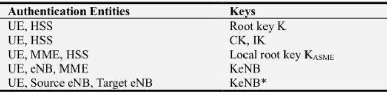
Table 1. LTE Network EPS-AKA Key Hierarchy.
Authentication Entities Keys
UE, HSS Root key K
UE, HSS CK, IK
UE, MME, HSS Local root key KASME
UE, eNB, MME KeNB
UE, Source eNB, Target eNB KeNB*
The authors in [15] elaborate that the root key (K) is utilized by the UE and the HSS to derive both Cipher key (CK) key and Integrity key (IK) key. Upon completion of mutual authentication between the UE and the HSS, the UE and the HSS derive the local root key, KASME, by binding
both CK and IK with MME identity to the key derivation function (KDF). Thereafter, HSS forwards the KASME to the
MME. In addition, KeNB key is derived from KASME key by
the UE and the MME, after which MME sends the KeNB to the eNB. The KeNB key is utilized for encrypting traffic between the UE and the eNB. Moreover, based on the KDF function, KeNB is employed by UE and eNB to compute KeNB*. During the handover process, the source eNB forwards KeNB* to the target eNB.
3. Methodology
To facilitate the prior buffering of the handover FOMs, the tracking area was partitioned into three regions namely the NHR, LPHR and HPHR as shown in Figure 1 and this constituted timing advance. At the center of the tracking area is the serving eNB and the UE is at liberty to shift to any of the partitioned regions at any particular waypoint.
Figure 1. Tracking Coverage Area Partitioning.
When the UE is at the NHR, the signal strength from the source eNB is very strong, and hence the scanning of the neighbouring eNBs is prohibited in this region. However,
when at the LPHR, the signal strength from source eNB is relatively weak and as such, the UE commences the process of analyzing beacons from the surrounding eNBs and buffering this information in the MME. At the HPHR, the serving eNB signal strength is very weak and the UE is handed-over to a neighbouring eNB with better figures of merit.
A part from the tracking area partitioning, the protocol adopted a combination of the random waypoint and random direction mobility prediction models. The random waypoint was chosen owing to its ability to depict motion waypoints, velocity and pause time while the random direction mobility model was selected because of its ability to incorporate direction changes after every waypoint. The random direction model was modified to address its border behavior specification problem by the incorporation of a border behavior to specify the reaction of mobile stations reaching the simulation area boundary, which was treated as the simulated obstacle.
In addition, the neuro-fuzzy inferencing mechanism, consisting of the knowledge base, database, inference engine, and the explanation facility, was utilized to optimize the handover process. The knowledge base consisted of handover conditions expressed in modus ponens statements that evaluated to HIGH or LOW. The database on its part acted as a repository of all measured handover FOMs such as power density, received carrier power, traffic density, call blocking probability and path loss.
The inference engine linked the rules in the knowledge base and FOMs in the database, and hence facilitated the execution of the handover decisions while the explanation facility provided justification for the choice of the target eNB. The neuro-fuzzy rules combined the various criteria using AND or OR logic connectors to arrive at appropriate conclusions, which were to deny or grant the handover to the subscriber. At any given moment during the time when the UE is in the cell overlapping region, the MME utilized this protocol to reduce the handover latency.
The developed protocol had two significant features that helped address security and delays during the handover process. The first feature was the timing advance facilitated by prior neighbor beacon scanning at LPHR upon which the handover FOMs were computed and buffered. Thereafter, the neuro-fuzzy inferencing mechanism utilized these parameters as inputs to optimize delays during the handover process. Regarding security, the developed protocol included an authentication mechanism to validate the UE requesting handover before new channel is allocated as shown in Figure 2 that follows.
Figure 2. Algorithm for Delay Sensitive Protocol.
As illustrated in Figure 2, the first phase was to partition the coverage area into three regions after which the FOMs were measured. This was followed by the instantiation of UE mobility using the random waypoint model but upon obstacle
detection, the random direction model with cluster boundary detection was activated. As long as the UE is moving within NHR, it should not scan the beacons from the neighbouring eNBs and only its movement coordinates are tracked.
However, as soon as the UE moves to the LPHR, it starts to analyze beacons from neighbouring eNBs and buffering their values in the neuro-fuzzy’s database. For an UE located at the HPHR, the neuro-fuzzy inference mechanism is invoked to provide a decision on whether a handover is necessary and if so, select the most promising target eNB. Thereafter, the previous eNB, requesting UE and the target eNB validated each other by exchanging validation credentials. Provided these credentials are valid, verification results are sent to the UE upon which the UE sends an acknowledgement to the target eNB. Next, the target eNB allocates a new channel to the UE and sends its timing information to the UE. Upon receipt of timing information, the UE shifts to the new channel and starts packet transmission. Finally, the BSC instructs the previous eNB to release the channel for subsequent use by the UEs within its NHR and LPHR.
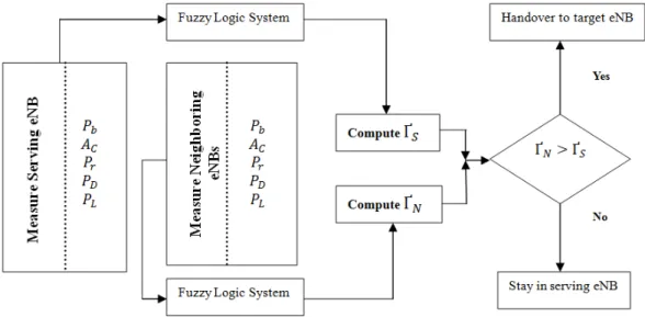
The neuro-fuzzy inference mechanism required the computation of a threshold handover factor, Ґ of the serving
eNB. Thereafter, the FOMs were measured from neighboring eNBs, combined and fed to the fuzzy logic system to compute the handover factor, Ґ . Here, if Ґ is greater than Ґ then the UE was handed over to the best available target
eNB, otherwise the next condition was evaluated as shown in Figure 3. Each of the fuzzy sets had five inputs and three membership functions, Low, Medium and High.
Figure 3. Modeling Neuro-Fuzzy Handover Optimization.
The neuro-fuzzy system’s knowledge base consisted of a set of IF---THEN rules, which together with the figures of merit in the database were the inputs to the fuzzy inference system. There were a number of antecedents that were combined using fuzzy operators which included AND, OR, and NOT. In this protocol, five fuzzy inputs variables and three fuzzy sets were designed for each fuzzy variable, hence the maximum possible number of rules in the knowledge base is 35=243. The following are examples of these rules:
RULE-1: If is low and is low and is low and is low and is low then handover factor is low.
RULE-243: If is high and is high and is high and is high and is high then handover factor is high.
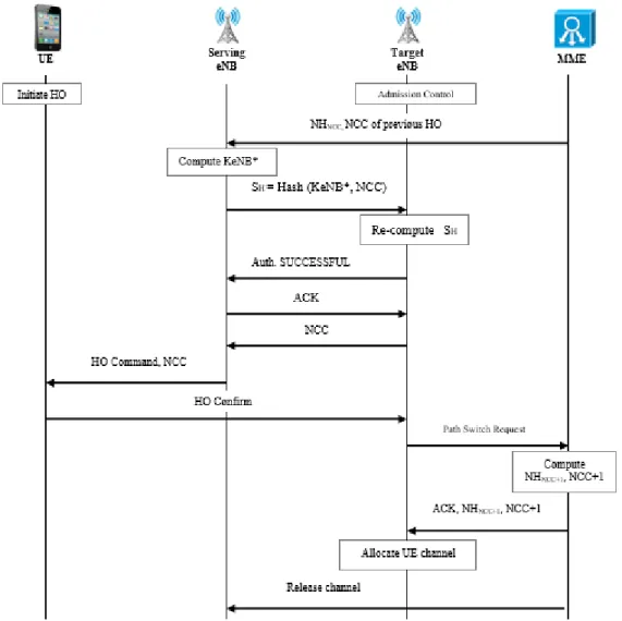
as shown in Figure 4, using Hashed Message Authentication Code- Secure Hashing Algorithm (HMAC-SHA-512) as the key distribution function (KDF).
In the developed protocol, the computation of KeNB* using current value of KeNB through horizontal key derivation is eliminated. Since the FOMs are already in the neuro-fuzzy database, there is no need for the UE to send measurement report to the serving eNB. In addition, the neuro-fuzzy inferencing mechanism has already selected the best target eNB and as such, the first step here is admission control where the target eNB reserves some channels to serve the new UE, which serves to reduce blocking probability.
During the second step, the serving eNB computes KeNB* using UE GUTI as KASME. In the third step, the serving eNB
sends hashed KeNB* and the Next Hop Chaining Counter (NHNCC) value via the X2 interface to the target eNB. In step
4 the target eNB re-computes the hash and provided the received hash and the re-computed hashes match, the target eNB sends authentication SUCCESSFUL message to the serving eNB.
In phase 5, the serving eNB acknowledges receipt of this message upon which the target eNB transmits NCC parameter to connect the UE with it in phase 6. In step 7, the serving eNB sends the handover request command to the UE together with NCC that has been sent from the target eNB after which the UE confirms the handover message to the target eNB as its new serving eNB in phase 8.
Figure 4. Multi-Factor Handover Process.
During step 9, the target eNB sends S1 path switch request message to the MME via S1 interface. In step 10, the MME receives path switch request and computes the fresh NH key and NCC values upon which it sends S1 path switch request acknowledgement message back to the new serving eNB, together with the NHNCC+1 and NCC+1 for next handover.
During step 11, the target eNB allocates the incoming UE the reserved channel for packet transmission. Finally, in
phase 12, the MME instructs the previous eNB to release the channel for the just handed over UE so that it can be used by other UEs within its NHR and LPHR.
4. Results and Discussions
when the UE moved to the HPHR. The FOMs that formed the inputs to the neuro-fuzzy inference are shown in Table 2
together with their measured ranges as determined at the LPHR.
Table 2. Neuro-Fuzzy Membership Functions.
Crisp Inputs Low Medium High Units
LB UB LB UB LB UB
Blocking probability 1.0 * e-10 9.0 * e-10 1.0 * e-8 9.0 * e-8 1.0 * e-7 9.0 * e-7 -
Power density -24 -23 -25 -24 -27 -25 dB
Path loss 9 10 10 11 11 12 dB
Traffic intensity 0.1 0.2 0.3 0.5 0.6 0.9 Erlang
As shown in Table 2, each of the membership functions of low, medium and high were each decomposed into lower bound (LB) and upper bound (UB) corresponding to the lower and upper concentric circles of the LPHR. To employ these membership functions (MF) in neuro-fuzzy inferencing, the crisp inputs were reduced to only two membership functions of LOW and HIGH as shown in Table 3 that follows.
Table 3. Optimized Neuro-Fuzzy Membership Functions.
Crisp Inputs Low High Units
Blocking probability <1.0 * e-8 >1.0 * e-8 -
Power density -22 to -12 -27 to -23 dB
Path loss -3 to 8 9 to 12 dB
Traffic intensity <0.4 >0.4 Erlang
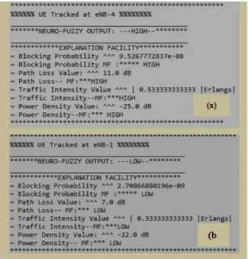
Using the membership functions in Table 3, a handover to the next eNB was only possible when the crisp output evaluated to a HIGH. However, for the rest of the crisp outputs, handovers to the next eNB was denied. Figure 5 presents crisp outputs that were obtained when an UE was tracked at eNB.
Figure 5. Neuro-Fuzzy Crisp Output.
In Figure 5 (a) the neuro-fuzzy crisp output was HIGH and the justifications are that blocking probability was
9.5267772837e-08, path loss was 11.0 dB, traffic intensity was 0.533333333333 Erlangs while power density was -25 dB. Using the membership functions in Table 2, blocking probability value of 9.5267772837e-08 >1.0 * e-8 and hence density value was -25.0 dB lay between -27 and -23dB, which was hence HIGH.
As such, the overall neuro-fuzzy output was HIGH since the overall handover factor was HIGH and hence rule-81 was invoked from the knowledge base. HIGH, path loss value of 11.0 dB lay between 9 and 12 dB and therefore was HIGH, traffic intensity value of 0.533333333333> 0.4 Erlangs and thus HIGH, and power density value was -25.0 dB lay between -27 and -23dB, which was hence HIGH. As such, the overall neuro-fuzzy output was HIGH since the overall handover factor was HIGH and hence rule-243 was invoked from the knowledge base.
Considering the crisp output of Figure 5 (b) the value of blocking probability was 2.70866880196e-09 which was less than 1.0 * e-8 and hence LOW, path loss was 7.0 dB which lay between -3 and 8 dB and thus LOW, traffic intensity was 0.333333333333 Erlangs, which was lower than 0.4 Erlangs, thus LOW, and power density value was -22 dB which lay between -22 and -12dB and hence LOW.
As such, the overall neuro-fuzzy output was LOW since the overall handover factor was LOW and hence rule-1 was invoked from the knowledge base. Based on the outputs in Figure 5, the neuro-fuzzy output of HIGH meant that a handover was possible to eNB-4 but a handover was denied from eNB-1. These membership functions were later used when the UE is at HPHR to make a handover decision as shown in Figure 6. As shown in Figure 6, a handover from eNB-7 to eNB-1 was detected and as such, a handover was initiated but before an UE can be handed over, the neuro-fuzzy inferencing was invoked to ensure that this handover occurs towards the most promising eNB.
Figure 6. Neuro-Fuzzy Optimized Handover.
Since the global decision from the inferencing is that handover is granted [GRANT HO], rule-243 applies.
developed protocol, the handover duration in the LTE network without the portioning of the coverage network was simulated. Figure 7 presents some of the latencies obtained for the first four handovers while Table 4 gives the handover latencies for the twelve sampled handover instances. As
shown in Figure 7 (a), the handover took approximately 2.808 seconds while that one in Figure 7 (b) took roughly 2.917 seconds. On their part, handovers in (c) and (d) lasted for 2.651 seconds and 2.957 seconds respectively.
Figure 7.Simulated Handover Latencies without Timing Advance.
On their part, handovers in (c) and (d) lasted for 2.651 seconds and 2.957 seconds respectively.
Table 4. Handover Latencies without Timing Advance.
Handover
Latency (Secs) Source eNB Target eNB
eNB-3 eNB-1 2.808
eNB-5 eNB-1 2.917
eNB-7 eNB-6 2.957
eNB-5 eNB-4 2.651
eNB-2 eNB-3 2.296
eNB-3 eNB-1 2.371
eNB-7 eNB-6 2.493
eNB-7 eNB-1 2.739
eNB-5 eNB-4 2.502
eNB-3 eNB-1 2.407
eNB-7 eNB-6 2.649
eNB-5 eNB-1 2.384
Average Latency 2.598
Based on the concept that conventional handovers are permitted to last for 0.5 to 1.5 seconds between handover command and handover execution, the developed protocol was configured to drop handover requests lasting for more than the lower bound of this range, that is 0.5 seconds.
As such, all the handovers initiated in Figure 7 where no timing advance information was available were dropped as
shown in Figure 8. This was meant to prevent tying the network resources for long durations for particular UEs at the expense of others. The next set of simulations on handover latencies were carried out using the developed protocol which implemented timing advance techniques whenever an UE was detected at the LPHR.
Figure 8. Request Termination for Long Latency Handovers.
Figure 9. Latency Analysis of Neuro-Fuzzy Handover.
In (a) an UE is being handed over from eNB -2 to eNB -3 taking roughly 0.033 seconds while in (b) an UE is being handed over from eNB -5 to eNB -4 taking approximately 0.033 seconds. In (c) the handover is from eNB -7 to eNB -6 while in (d) the handover is from eNB -3 to eNB -1 taking approximately 0.042 and 0.036 seconds respectively. The same process was repeated for other handover procedures to yield the latencies shown in Table 5. Based on these values, it is evident that the developed protocol exhibited very short handover latencies and hence had low chances of causing denial of services requested.
Table 5. Handover Latencies with Timing Advance.
Handover
Latency (Secs) Source eNB Target eNB
eNB-7 eNB-6 0.042
eNB-5 eNB-4 0.033
eNB-3 eNB-1 0.036
eNB-2 eNB-3 0.033
eNB-7 eNB-6 0.074
eNB-5 eNB-4 0.039
eNB-3 eNB-1 0.025
eNB-7 eNB-1 0.057
eNB-2 eNB-3 0.025
eNB-3 eNB-1 0.076
eNB-7 eNB-6 0.040
eNB-5 eNB-4 0.078
Average Latency 0.048
To further address DOS, average handover latency was computed based on the values in Table 4, which was established to be 0.048 seconds as shown above. Figure 10 compares the handovers without timing advance and handovers with timing advance graphically.
Figure 10. Handovers with and without Timing Advance Comparisons.
In Figure 10, the upper graph is that of handovers without timing advance while the lower graph is that of handovers with timing advance. Comparing the latency values in Table 4 with those in Table 5, and their graphical representations in Figure 10, it is evident that partitioning the coverage area into NHR, LPHR and HPHR and starting probing neighbouring beacons at LPHR and buffering these values in the neuro-fuzzy database, and employing the neuro-fuzzy inferencing mechanism in selecting the most ideal target eNB greatly reduced the handover latencies. For instance, the average latencies in Table 4 were 2.598 seconds against an average latency of 0.048 seconds in Table 5.
eNB-5 to eNB-4 illustrated in Figure 11, the first step during the handover was admission control where the target eNB reserves some channels to serve the new UE, which serves to reduce blocking probability.
The next phase was that of LTE-A authentication which involved the usage of previous handover values for NHNCC,
together with the Physical Cell Identity (PCI) and E-UTRAN Absolute Radio Frequency Channel Number on the Download (EARFCN-DL) to derive KeNB*. In addition, SH was derived by using encrypted NCC and the just
computed KeNB* as inputs to the key distribution function (KDF).
During the second step, the authentication process is started in which eNB-5 derived KeNB* using UE salted and hashed GUTI as KASME. In the third step, eNB-5 sent SH
value via the X2 interface toeNB-4 as demonstrated in Figure 12. In step 4, eNB-4 re-computed SH and since the received SH and KeNB* from eNB-5 and the re-computed SH at eNB-4 match, it sent authentication SUCCESSFUL message to the eNB-5.
Figure 11. Source eNB Authentication Tokens.
In phase 5, eNB-5 acknowledged receipt of this message upon which eNB-4 transmitted NCC parameter to connect the UE with it in phase 6. In phase 7, eNB-5 sent the handover request command (HO CMD) to the UE together with NCC that has been sent from eNB-4 after which the UE confirmed the handover message to eNB-4 as its new serving
eNB in phase 8. During step 9, eNB-4 sent S1 path switch request message to the MME via S1 interface. In step 10, the MME received path switch request and computed the fresh NH key and NCC values upon which it sent S1 path switch request acknowledgement message back to eNB-4, together with the NHNCC+1 and NCC+1 for next handover.
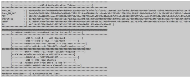
Figure 12. Target eNB Authentication Tokens.
During step 11, eNB-4 allocated the incoming UE the reserved channel for packet transmission. Finally, in phase 12, the MME instructed eNB-5 to release the channel for the just handed over UE so that it can be used by other UEs within its NHR and LPHR. The handover duration for all these processes was 0.0329999923706 seconds.
5. Conclusion
an UE is detected at LPHR, beacons from the neighbouring eNBs were analyzed and the resulting FOMs buffered in the MME. The simulations results have shown that handovers with this timing advance exhibited lower delays of an average value of 0.048 seconds compared with handovers without timing advance which had an average delay of 2.598 seconds. The extra created time was then utilized to authenticate the handover entities so as to preserve subscriber privacy and ensure security of the communication process. Future work lies in the investigation of how the developed protocol performs in other cellular networks. There is also need to validate the developed authentication protocol against conventional cellular network attacks.
References
[1] Basaras P., Belikaidis I., Maglaras L., and Katsaros D. (2016). Blocking epidemic propagation in vehicular networks, in Wireless On-demand Network Systems and Services (WONS), 12th Annual Conference on. IEEE, pp. 1–8.
[2] Babiker A., H. Ahmmed H., & Ali S.(2016). Comparative Study 1st, 2nd, 3rd, 4th, Generations from Handoff Aspects. International Journal of Science and Research, Vol. 5, Issue 6, pp. 934-941.
[3] Kastell K., Meyer U.,& R. Jakoby R. (2013). Secure Handover Procedures. Department of Computer Science, Darmstadt University of Technology, pp. 1-5.
[4] Osahenvemwen O., & F. Odiase F. (2016). Effective management of handover process in mobile communication network. Journal of Advances in Technology and Engineering Studies, Vol. 2, Issue 6, pp. 176-182.
[5] Zhang L., and Pierre S. (2014). An enhanced fast handover with seamless mobility support for next-generation wireless networks, Journal of Network and Comput. Applications, Vol. 46, pp. 322 – 335.
[6] Sridevi B., and Mohan D. (2015). Security analysis of
Handover Key Management among 4G LTE entities Using Device Certification, International Journal of Electrical, Computing Engineering and Communication, Vol. 1, No 2, pp. 1-7.
[7] Lin Y., Longjhuang W., & Chen Yang C. (2015). Enhanced 4G LTE Authentication and Handover Mechanism. International Journal of Electrical, Electronics and Data Communication, Vol. 3, Issue 9, pp. 45-47.
[8] Han C., and Choi H.(2014). Security analysis of handover key management in 4G LTE/SAE networks, IEEE Trans. Mobile Comput., Vol. 13, No. 2, pp. 457- 468.
[9] Tayade P., and Vijaykumar P. (2017). A Comprehensive Contemplate on Security Aspects of LTE and LTE Advanced in Wireless Communication Network, International Journal of Control Theory and Applications, Vol. 10, No 31, pp. 197-217.
[10] Agarwal P., Thomas D., and Kumar A. (2017). Security Analysis of LTE/SAE Networks under De-synchronization Attack for Hyper-Erlang Distributed Residence Time, IEEE Communications Letters, Vol 21, No 5, pp. 1055-1058.
[11] Cao J., Ma M., Li H., Zhang Y., and Luo Z. (2014). A survey on security aspects for LTE and LTE-A networks, IEEE Commun. Surveys TUTs., Vol. 16, no. 1, pp. 283–302.
[12] Lai Y., Cheng P., Lee C., & CKu C. (2016). A New Ticket-Based Authentication Mechanism for Fast Handover in Mesh Network. Department of Photonics and Communication Engineering, Asia University, Taichung, Taiwan, pp. 1-18.
[13] Copet P., Marchetto G., Sisto R., & Costa L. (2015). Formal Verification of LTE-UMTS Handover Procedures. IEEE, pp. 1-8.
[14] Degefa F., Lee D., Kim J., Choi Y., and Won D. (2016). Performance and security enhanced authentication and key agreement protocol for SAE/LTE network, Computer Networks, Vol 94, pp. 145-163.