PERFORMANCE ANALYSIS OF SPECTRUM SENSING IN
OFDM SYSTEMS APPLICATIONS
Pendli Pradeep
PG Scholar, Dept of ECE, M Tech, Digital
systems and computer electronics,
Sreenidhi Institute of Science and Technology,
Yamnampet,Ghatesar,Hyderabad-506301 India
Mr.S.P.V Subba Rao
Associate Professor, Dept of ECE,
Sree Nidhi Institute of Science & Technology,
Hyderabad,
India.
ABSTRACT
Spectrum sensing is one of the core technologies of Cognitive Radio (CR) systems which provide a viable solution to the problem of sparsity of wireless spectrum. Nowadays, OFDM techniques are adopted by many existing or progressing wireless communication standards. Accuracy and speed of estimation are the key indicators to select the appropriate spectrum sensing technique. Multi-carrier techniques such as OFDM are widely adopted in the physical layer of nowadays radio communication and broadcasting systems.Therefore in cognitive radio, a robust spectrum sensing techniques for such signals is highly desired. Cyclic Prefix (CP), Time-Domain Symbol Cross-correlation based spectrum sensing (TDSC) methods are used for sensing the spectrum. TDSC method have advantages in sensing accuracy and robustness compared to CP. CTDSC method using 64DAPSK modulation is used and compared with CTDSC QAM and it results 1dB SNR improved over QAM.
Keywords
: Cognitive Radio, OFDM, Spectrum Sensing.1.
INTRODUCTION
Orthogonal frequency division multiplexing (OFDM) divides the high speed data stream into lower speed parallel ones, overlaps the frequency bands of sub-channels, it is robust against multipath interference and has high spectrum efficiency. OFDM has been widely used, and it is also the first-selection technology for the Fourth Generation (4G) mobile communication. The decision directed method uses all of the sub-carriers of the OFDM signal to estimate the channel.
Spectrum sensing is a critical task in cognitive radio (CR) to decrease the interference level to the primary network. Most important and critical task of a CR is to sense the spectrum to obtain awareness about the spectrum usage and existence of primary users in a geographical area. Spectrum sensing is the ability to measure, sense and be aware of the parameters related to the radio channel characteristics, availability of spectrum and transmit power, interference and noise, radio’s operating environment, user requirements and applications, available networks (infrastructures) and nodes, local policies and other operating restrictions.
On the other hand, the pilot symbol-aided method uses the multiplexed pilot in the transmitted signal to estimate the channel. Recently, diverse orthogonal frequency division multiplexing (OFDM) systems became candidates for the CR, e.g., digital video broadcastings (DVBs) and wireless local area networks (WLANs) for the TV white spectrum space [1],due to their spectrum utilization and robustness against fading.
The DTV signal in Europe is an OFDM-based signal defined by DVB-T and DVB-T2 Standards [4][5]. There are also many existing or progressing standards which adopt an OFDM transmission technique.
2.
SPECTRUM SENSING OF OFDM SIGNAL
Fig.1 shows the block diagram for spectrum sensing of OFDM signal. The objective of spectrum sensing is to decide whether there are OFDM signals, given the signal {y[n], n = 0, 1,…, S-1} received via a multipath fading channel with complex additive white Gaussian noise (AWGN), where S is the time duration for sensing. Let Xl [k] be the transmitted symbols at the k-th sub-carrier in the l-th frequency-domain OFDM symbol. Also let w[n] be the i.i.d. circularly symmetric complex AWGN with zero mean and σ2w/N variance. Then, the absence hypothesis H0, representing the white spectrum, and the presence hypothesis H1 are typically modeled as [3].
SPECTRUM SENSING FOR DVB-T OFDM SYSTEMS
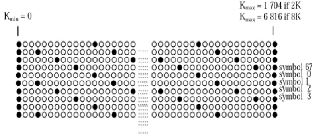
According to [10], every transmitted OFDM symbol contains two kinds of pilot tones. One is continued pilot and the other is scattered pilot. The positions of continued pilots are the same for all transmitted OFDM symbols. The scattered pilots are inserted every twelve subcarriers and their positions are shifted by three subcarriers for the next OFDM symbol so that the positions of scattered pilots are repeated every four OFDM symbols,. Therefore, there are four sets of pilot tone patterns for DVB-T OFDM. We should note that the number of scattered pilots is much larger than the number of continued pilots. For a 2K-subcarrier mode, there are 45 continued pilot tones and 141 scattered pilot tones in an OFDM symbol. Therefore, we shall compute C(ν) for the case where ν is a multiple of four, except zero, because by doing so, the absolute mean value of C(ν) is maximized. The decision statistic is given by
3.
TDSC SPECTRUM SENSING METHODS
The proposed algorithm utilizes the property that the Time-Domain Symbol Cross-Correlation (TDSC) of two OFDM symbols having the same pilot pattern generates a nonzero constant term. Thus it is named the TDSC algorithm. The TDSC method can be applied to any multi-carrier system which allocates frequency domain pilot tones for synchronization and channel estimation.
A.
TDSC METHOD
are inserted every twelve subcarriers and their positions are shifted by three subcarriers for the next OFDM symbol so that the positions of scattered pilots are repeated every four OFDM symbols, which is depicted in Fig.1
Fig 1. Periodical pilot tone pattern in DVB-T
Let xl[n] be the received samples within the l-th OFDM symbol period. Assume the l-th and the m-th symbols have the same pilot pattern and define
(1)
which is the Time-Domain Symbol Cross-correlation (TDSC) function of the two symbols. Let v = l−m be the symbol index difference, the accumulated TDSC function.
B.TDSC-MRC METHOD
Maximal Ratio Combining Approach
For a period of received signal, we can compute (𝜈) for different 𝜈. Since the noise terms (𝜇) embedded in the accumulated TDSC functions are independent for different 𝜈’s, it is expected that some performance gain can be obtained by combining various TDSC functions (𝜈) for different values of 𝜈. However, the (𝜈) corresponding to different 𝜈 cannot be linearly combined to perform spectrum sensing due to different phase terms (𝜈) in (4) caused by carrier frequency offset. In order to solve this problem, which is the conjugate product of two accumulated TDSC functions. Then the phase term embedded in (𝜈, 𝜈 + 𝑑) becomes a function of 𝑑, and hence, we can linearly combine (𝜈, 𝜈 + 𝑑) for different
𝜈. Therefore, let 𝑇 be the linear combination of (𝜈, 𝜈 + 𝑑), that is
(2)
be formed and the optimal decision statistic is ∣𝑇∣. The problem arises as to how the 𝑎v should be chosen so as to achieve the best detection performance for a fixed probability of false alarm.
TDSC-MRC Method
One well-known decision framework for the spectrum sensing is the TDSC-MRC hypothesis testing using pilot symbols inserted with symbol spacing M [5]. The pilot symbol pattern is shifted by symbol shift index D for the next OFDM symbol, so identical pilot symbol pattern is repeated every A (= M/D) OFDM symbols. The decision statistic TT DSC−MRC ({y[n], n = 0, 1,…, S-1}) is given as
TTDSC-MRC less than or greater than threshold value Threshold γ0 based on the false alarm probability PFA is defined as
(3)
4.
MISDETECTION AND FALSE ALARM
A.
Probability of Misdetection
The probability distributions for the two hypotheses of TDSC-based spectrum sensing algorithms are circularly symmetric complex Gaussian Let 𝜎2
H0 and 𝜎2H1 be the variances of the distributions of the two hypotheses and 𝜇H1 be the mean of the distribution of the hypothesis 𝐻1. For hypothesis 𝐻0, and ∣𝑇𝑀𝑅𝐶∣ are both Rayleigh distributed. Hence, for a specific probability of false alarm 𝑃𝐹𝐴, the corresponding threshold 𝛾 is given by (8). For the case of a single-path channel, the corresponding probability of misdetection 𝑃𝑀𝐷, is given by
(4)
Note that the misdetection probability of the TDSC based spectrum sensing algorithms given in (9) is based on the TDSC function described by [8] Thus, the misdetection probability calculated by (9) is not exactly the theoretical misdetection probability of the TDSC-based spectrum sensors. However, it is appropriate to expect that (9) is a good indicator of the actual misdetection probability. As a result, the misdetection probability under the multipath channel condition will be larger than the misdetection probability under the single-path channel condition. In general, the misdetection probability given by (9) provides a useful reference for detector performance of the corresponding TDSC based spectrum sensing algorithms.
B.
Probability of False Alarm
1) TDSC Based Method: As mentioned in the previous section, for a specific 𝑃𝐹𝐴, the corresponding threshold 𝛾 is given by (8). In the case the CP ratio of 1/32 and a sensing time of 50 ms are chosen. The threshold is set according to (8) which are for TDSC-NP method.. 𝑃𝐹𝐴 with corresponding thresholds are very close to the desired values of 𝑃𝐹𝐴
5.
C-TDSC-MRC METHOD USING DAPSK MODULATION
w(n)
Y[n]
y[n]
Fig 2. Block diagram of the OFDM system transmitter, multipath fading channel, and the proposed C-TDSC-MRC method for spectrum sensing.
The C-TDSC-MRC method in Fig.2 employs D parallel pairs of cross-correlator and comb filter, where each correlatorfilter pair deals with mutually exclusive sub-band, while covering whole OFDM frequency band to detect all the pilot symbols of an OFDM symbol suffering certain amount of frequency offset. If the number of parallel pairs is less than D, some pilot symbol pattern(s) cannot be detected, thereby SNR improvement due to comb filters is only partially achieved. Frequency response of individual comb filters when D = 3 is presented
The peaks of a comb filter are located at every D symbols. The output signal of the d-th comb filter zd [n] in the d-th correlator-filter pair is given in [9] as
(5)
where || · || denotes the nearest integer function. With a correlator-filter pair, computational complexity for the comb filtering in above equation is much smaller than that of the computationally intensive correlation in (2). Then, the decision statistic for the C-TDSC-MRC method is given as
(6)
where TC−T DSC−MRC,d = TT DSC−MRC ({zd [n], n = 0,1,…, S-1}), i.e., TC−T DSC−MRC,d is the statistic obtained by replacing y[n] with zd [n]. The threshold γ for the C-TDSC-MRC method is calculated by considering the absence hypothesis H0 in (4). Let y[n] =w[n], then C(mA) of the d-th pair, Cd (mA), can be shown to be a circularly symmetric
Data
source DAPSK IIFT CP insertio
n
Multipath fading channel
+
Comb filter 0
TDSC-MRC 0
Max0<d<=D-1TC-TDSC-MRC >H1<H0
Y
Comb filterD-1 Comb filter 1
TDSC-MRC 1
complex Gaussian random variable with zero mean and variance 3σ4w/{8 (S − mANs ) N2} for all the correlator-filter pairs. Var(MC(A)) for σ2H0 of the C-TDSC-MRC method, the threshold γ in (eq.7) is given by
(7) the complexity of the C-TDSC-MRC method is about D times as much as the TDSC-MRC methods. Note that D = 3 for the DVB-T2 standard [1].
6.
SIMULATION RESULTS
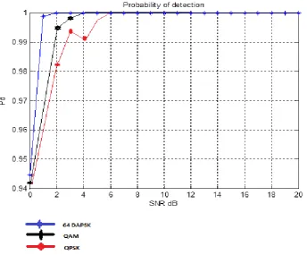
The TDSC-MRC method can achieve probability of detection with respect to SNR for a false alarm probability of 0.1 for SNR values of 0 dB and 20 dB, respectively. The new spectrum sensing method employs parallel pairs of cross-correlators and comb filters, reducing the effect of random data signals by comb filters. The performance of the C-TDSC-MRC method using DAPSK Modulation is improved by about 1 dB in SNR over the C-C-TDSC-MRC method due to the reduced random data signals.
By simulating the Different values of 64 data symbols from the source it passed through multi path fading channel SNR is improved well after certain SNR value i.e when SNR is improved from 0 dB to 20dB in fig3 the probability of detection is improved for a probability of false alarm Pfa=0.1
7.
CONCLUSION
New TDSC-MRC method parallel pairs of cross correlator and comb filter is used for sensing OFDM signals. Due to significant reduction of random data signals by the filter bank, Simulation results show that this new architecture presents good detection performance
Simulation results show that the proposed method provides improvement of the sensing performance by about 1dB in SNR over the C-TDSC-MRC method. Since SNR gain by comb filtering does not depend on the type of TDSC method, the SNR gain is sustained when the NP method is adopted instead of the MRC method.
In this paper in place of QAM/QPSK modulation DAPSK modulation is used so 1dB in SNR improved over previous modulation.
8.
REFERENCES
[1]
Digital Video Broadcasting (DVB); Framing Structure, Channel Coding, and Modulation for a
Second Generation Digital Terrestrial Television Broadcasting System (DVB-T2), EP Standard EN
302 755,Sep. 2009.
[2]
ETSI, ―Digital Video Broadcasting: Framing Structure, Channel Coding, and Modulation for Digital
Terrestrial Television,‖ vol. ETSI EN 300 744 V1.6.1 (2009-01), 2009.3.
[3]
H. Chen, W. Gao, and D. G. Daut, ―Signature based spectrum sensing algorithms for IEEE 802.22
WRAN," in Proc. IEEE ICC CogNets Workshop, pp. 6487-6492, Glasgow, Scotland, June 2007.
[4]
ETSI, ―Digital video broadcasting: framing structure, channel coding, and modulation for digital
terrestrial television," European Telecommunication. Standard EN300744, Aug. 1997.
[5]
ETSI, ―Frame structure channel coding and modulation for a second generation digital terrestrial
television broadcasting system," European Telecommunications. Standard DTV Doc. A122, June
2008.
[6]
IEEE Standard, ―IEEE Standard for information technology telecommunications and information
exchange between systems local and metropolitan area networks-specific requirements—part 11:
wireless LAN medium access control (MAC) and physical layer (PHY)specifications," IEEE, New
York, June 2007.
[7]
S. Shellhammer and R. Tandra, ―Performance of the power detector with noise uncertainty," IEEE
802.22-06/0134r0, July 2006.
[8]
H. S. Chen, W. Gao, and D. G. Daut, ―Spectrum sensing for OFDM systems employing pilot tones,‖
[9]
S. L. Talbot and B. Farhang-Boroujeny, ―Spectral method of blind carrier tracking for OFDM,‖ IEEE
Trans. Signal Process., vol. 56, no. 7, pp. 2706–2717, Jul. 2008.
[10]
ETSI, ‖Digital Video Broadcasting: Framing Structure, Channel Coding,and Modulation for Digital
Terrestrial Television,‖ European Telecommunication Standard EN300744, August 1997.
[11]