Research Article
a
April
2018
Special Issue: National Conference on Emerging Trends in Engineering 2018
Conference Held at Sri Venkatesa Perumal College of Engineering & Technology, Puttur, A.P., India
Computer Science and Software Engineering
ISSN: 2277-128X (Volume-8, Issue-4)
Dynamic Modeling and Performance Analysis of Wind
Driven Self-Excited Induction Generetor
P. Anjani Mrudula 1, S. Reshma Sony2, Ch. Lenin Babu3
1, 2
UG Student, Dept. of EEE, SVEW
3
Assistant Professor, Dept. of EEE, SVEW
Abstract: In present days, the use of wind energy is growing rapidly to generate and supply electricity as grid connected or standalone mode. To generate electric power from such non-conventional sources, self-excited induction generator (SEIG) is found to be a suitable option for either using in grid connected mode or isolated mode. But the problems associated with SEIG are its poor voltage and frequency regulation under load and prime mover speed perturbations which put a limit on the use of SEIG for a long time. By controlling active and reactive power accurately, it is possible to regulate frequency and voltage of SEIG terminal during load and speed perturbations. In this paper, wind turbine driven SEIG system is simulated by taking different types of loads such as resistive load, R-L load, induction motor (IM) load to investigate the fault identification methodologies of SEIG system. Also, presents the step-by-step development of models for different units of the SEIG with the steady-state and transient analysis for performance prediction and design of excitation capacitor. The wind turbine driven SEIG system of 4.2 kW and a 3.7 kW induction machine are taken and simulated in MATLAB/Simulink environment.
Keywords: Renewable energy; Self-excited induction generator, Fault detection, Capacitance excitation.
I. INTRODUCTION
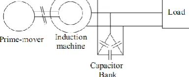
Currently to meet the never-ending electrical energy demand, researchers are giving more emphasize on renewable energy sources such as the wind, solar, small hydro and biogas. Out of the available renewable energy sources, wind power is clean and abundantly available in vast areas like mountain, on the shore, offshore, remote and isolated areas. The wind turbine converts the kinetic energy available in the wind into mechanical energy. Due to lower cost, rugged construction and maintenance-free operation induction generators are found to be an excellent option for wind power plants. Induction generator requires an adequate amount of reactive power which must be provided externally to set up the magnetic field needed to convert the available mechanical power at its shaft into electrical power. Reactive power can be supplied to the induction generator by connecting it to with grid, and this mode is called a grid-tied mode. Alternatively, by connecting appropriate value of capacitor bank, reactive power can be supplied to the induction generator. Such mode is called an isolated or stand-alone mode, and the generator is called Self-Excited Induction Generator (SEIG). Prime mover for the SEIG may be a wind turbine. Steady state and transient analysis of such wind turbine driven SEIG system are beneficial for design and performance prediction of the SEIG system. Wind turbine driven SEIG system is used in isolated areas where an extension of the grid is not feasible. The wind turbine employed in these areas is up to 100 KW rating and called a small wind turbine.
II. MODELING OF WIND TURBINE
The following figure shows schematic diagram of a SEIG system, where the prime mover is a wind turbine.
Figure 1: schematic diagram of a SEIG system
The power available in the wind is given by the time-rate of kinetic energy of the flowing air mass and expressed as follows
(𝐶𝑝 = 𝑝𝑡
𝑝𝜔) Coefficient of the wind turbine. Theoretical maximum value of Cp is (0.59) given by Betz limit but in
ISSN(E): 2277-128X, ISBN: 978-93-87396-07-4, pp. 32-37
blade pitch angle (b ), given by equation .Cp(l ,b ) = 0.5176 where, r is the radius of the swept area of the wind turbine in m. wT is the turbine angular speed in rad/s. For the wind turbine of 4.2 kW with pitch angle, b = 0◦ the Cp versus l has the shape.
Mechanical power versus turbine speed plot for this type of fixed turbine is shown in fig
Fig.2: shows power coefficient (𝐶𝑝)𝑣𝑠tip speed ratio (λ)
The maximum power extracted by the .turbine and the turbine speed at which the maximum power occurs increase with the increase in the wind speed.
III. DETERMINATION OF MINIMUM EXCITATION OF CAPACITANCE VALUE FOR THE SEIG For determining minimum capacitance value, the per-phase equivalent circuit of three phase. All the variables and parameter values are expressed in per unit (p.u) for convenience of analysis. The simplified representation of the circuit
and the total impedance of the circuit is represented by Zt, where,
F is the ratio of air gap voltage to frequency, which depends on the magnetic flux and hence magnetizing reactance Rs, Rr, RL, Xls, Xlr, XL are stator resistance, rotor resistance and load resistance, stator leakage reactance, rotor leakage reactance and load reactance respectively.
Xm is p.u saturated magnetizing reactance.
By applying loop analysis to the circuit at steady state, the expression obtained is IsZt = 0 … (3)
where Is is the steady state stator current. The self-excitation process of SEIG requires that the current in the loop, is not zero. So at, steady state Zt = 0
Cmin = 1/ w (Xls+Xm)𝑛2 … (4)
From the above equation, it is concluded that minimum excitation capacitance Cmin required
for SEIG during no load condition varies inversely as sum of leakage reactance and magnetizing reactance and also the rotor speed of the SEIG. To validate the developed expression, the calculated capacitance value is used in simulation and experiment on the SEIG.
IV. MODELING OF SEIG
Steady-state performance of SEIG can be evaluated using per-phase equivalent circuit approach, but it has limitations to analyze the transient phenomenon .To analyze the dynamic performance of SEIG under different types of loading condition, in this section
the d−q axis stationary frame model of induction machine is presented. Using d−q components of the stator and rotor currents 𝑖𝑠𝑑, 𝑖𝑠𝑞. 𝑖𝑟𝑑 𝑎𝑛𝑑𝑖𝑟𝑠 as state variables, electrical dynamics of the SEIG is represented by state-space model and
magnetizing current is given by As the magnetization
characteristic of SEIG is nonlinear, magnetizing inductance Lm varies with magnetizing current im. From synchronous speed test, relation between magnetizing inductance Lm and magnetizing current im are obtained and expressed as Lm = f (im) … (6)
The torque balance equation of the SEIG is
Tdrive = Te+J … (7) where, Tdrive is the mechanical input torque of SEIG. J is the moment of inertia of rotor. P is the number of poles of SEIG, respectively. Capacitor being one major part of SEIG, the excitation modeling for SEIG system is described in the next section.
V. EXCITATION MODELING
The excitation system dynamics are described using d−q components of stator voltage (vsd and vsq). Three-phase SEIG voltages and currents are transformed from a−b−c to d−q stationary reference frame and vice-versa. Reference frame and vice-versa, using equations. The value of minimum capacitor required for voltage build up of SEIG as determined from is substituted in the equations and The d −q modeling of different types of load are described in the next section.
ISSN(E): 2277-128X, ISBN: 978-93-87396-07-4, pp. 32-37
The d and q axis current equation for the Rload connected to SEIG are given as
𝑖𝑙𝑑 = 𝑣𝑠𝑑
𝑅𝑙𝑑 … (8) 𝑖𝑙𝑞 =
𝑣𝑠𝑞
𝑅𝑙𝑞 … (9) where, Rldand Rlqare d and q components of load resistances.
For R-L load:
The d and q axis current equation for the R-L load connected to SEIG are given as
where, Lldand Llqare d and q components of load inductances.
VI. MODELING OF INDUCTION MOTOR AS DYNAMIC LOAD
Three phase induction motor (IM) is often used as a dynamic load on SEIG. The d–q model of symmetrical three phase squirrel cage IM in the current form is given by
Where,
Where, isdm and isqm, are d and q components of stator currents of IM load, respectively. irdm and irqm, are d and q
components of rotor currents of IM load, respectively. vsdm, vsqm, are d and q components stator voltages of IM load,
respectively. vrdmand vrqmare d and q components rotor voltages of IM load, respectively. mmis mechanical rotor speed
of IM load. Rsmis stator resistance of IM load. Rrmis rotor resistance of IM load. Llsmis stator leakage inductance of IM
load. Llrmis rotor leakage inductance of IM load.Lmmis unsaturated mutual inductance of IM load.
The developed electromagnetic torque and torque balance equations of the IM load, are given as
where, TLmis load torque applied to IM load, Jmis moment of inertia of IM load, ωrmis electrical rotor speed of IM load
and Pmis number of poles of IM load.
VII. LOAD MODELING
Different types of load such as R, R−L and induction motor (IM) load are normally connected to the wind turbine driven SEIG system. To get the performance of complete system, modeling of only wind turbine and SEIG are not sufficient. Additionally, modeling of loads is also essential. These are presented in the subsequent subsections.s
VIII. PERFORMANCE OF SEIG IN DIFFERENT LOADING CONDITIONS
ISSN(E): 2277-128X, ISBN: 978-93-87396-07-4, pp. 32-37
(a) Performance of SEIG system during R load:
A star connected resistive load of 100 Ω/phase is connected with SEIG at t=1 s for the simulation. Resistive load draws active power from the SEIG, which causes voltage drop across stator impedance. As a consequence SEIG terminal voltage reduces causing the reduction of reactive power. Finally terminal voltage settles at a value below the rated voltage.
Fig.3 shows the performance of SEIG during R load
(b). Performance of SEIG during R-L load:
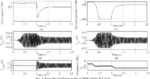
The performance of SEIG during R − L load switching is studied by connecting a R − L load of 0.9 power factor, Z = 100 + j48.42 Ω/phase to SEIG at t=1 s. In this type of loading, SEIG provides only active power to the load, and excitation capacitor provides reactive power to the load.
Fig. 4 shows the simulation results of SEIG during R-L load.
(c). Performance of SEIG system feeding induction motor:
In order to observe the performance of SEIG, an induction motor(IM) is connected with the wind driven SEIG. The specifications of IM taken as load are: 1.5kW,415v,3.2A,50Hz,1500rpm,delta-connected.
ISSN(E): 2277-128X, ISBN: 978-93-87396-07-4, pp. 32-37
Fig. 5 shows the simulation results of SEIG fed IM load.
Table 2: shows the comparison of simulation versus experimental results.
IX. RESULTS AND DISCUSSION
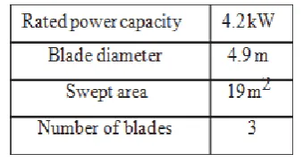
To develop the wind turbine driven SEIG system, a 4.2 kW wind turbine and a 3.7 kW induction machine are taken and simulated in MATLAB/Simulink environment.
Table.3 shows the parameters of wind turbine model.
Parameters of the induction machine used as SEIG are measured by conducting different tests (d.c resistance test, blocked rotor test and synchronous speed test) in the laboratory. The parameters of the 3.7 kW, 415 V, 7.5 A, 50 Hz, 1500 rpm. SEIG obtained from experiments are given in Table.4
Table.4 shows the parameters of induction motor used as SEIG.
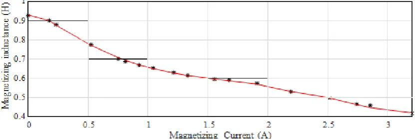
The magnetization characteristic of the SEIG is nonlinear. From the synchronous speed test, the relation between magnetizing inductance Lmand magnetizing current im is obtained and represented in the form of a polynomial. A
fifth-degree polynomial is taken in this thesis and given as:
ISSN(E): 2277-128X, ISBN: 978-93-87396-07-4, pp. 32-37
Fig. 6 shows the graph of identified magnetizing inductances vs magnetizing currents.
Table.5 shows the constants of magnetization characteristics of SEIG.
X. CONCLUSION
An analytical expression for the minimum value of capacitance required to develop SEIG rated voltage and frequency is derived. Mathematical model of wind turbine driven SEIG system is reviewed, Simulation of developed wind driven SEIG model is carried out in MATLAB/Simulink environment. The performance of wind turbine driven SEIG system taking different types of load such as resistive load, R−L load, induction motor (IM) load is discussed. Voltage can be compensated to some extent by increasing the excitation capacitance value. It is observed that SEIG voltage and frequency vary with load, prime mover speed and excitation capacitance. Hence, SEIG demands voltage and frequency controller to maintain SEIG voltage and frequency.
REFERENCES
[1] Y. K. Chauhan, S. K. Jain, and B. Singh, “Operating performance of static series compensated threephase self-excited induction generator,” Int. Jour. of Electric Power and Energy Syst., vol. 49, pp. 137–148, July 2013. [2] B. V. Perumal, “An investigation on some operational aspects of a generalized impedance controller based self
excited induction generator,” Ph.D thesis, IIT Delhi, Aug. 2006.
[3] G. K. Kasal, “Analysis, design and development of voltage and frequency controllers for asynchronous generators in isolated power generation,” Ph.D thesis, Delhi, Dec. 2008.
[4] K. Idjdarene, D. Rekioua, T. Rekioua, and A. Tounzi, “Performance of an isolated induction generator under unbalanced loads,” IEEE Trans. Energy Convers., vol. 25, no. 2, pp. 303–311, 2010.