Available online throug
ISSN 2229 – 5046COMPARISON OF TECHNICAL CAPABILITIES VARIOUS SERIES OF
LOCOMOTIVES OF THE MONGOLIAN RAILWAYS BASED ON MATHEMATICAL MODELING
G. BUREN-ITGEL
1, V. A. PRECHISSKI
1AND G. MUNKHSAIKHAN*
21FSUE HPE «MPEI», 111250 Krasnokazarmennaya Ulitsa, building 14,
Moscow, Russian Federation.
2School of Applied Sciences, Mongolian University of Science and Technology,
Main Campus, Khoroo 8, Bagatoiruu, Sukhbaatar District, Ulaanbaatar 14191, Mongolia.
(Received On: 20-12-18; Revised & Accepted On: 29-01-19)
ABSTRACT
T
he current article revises a full locomotive’s mathematical model, including the power regulator of the traction generator, transition processes during reswitching of master controller, traction generator and dynamic processes. Based on the suggested model, the 2TE116UM and 2TE10MK locomotive types are being compared. Those locomotives are commissioned at the Ulan Bator railway due to the renewal of locomotive fleet. Modeling of locomotive velocity demonstrated that, regardless of their supreme power parameters, the 2TE10MK locomotive has a lower thrust, thus, a lower velocity on higher gear positions. Nevertheless the economical parameters of 2TE10MK operation (fuel and oil consumption, failure rates) are more advantageous. Recommendations on rational selection of locomotive for Ulan Bator railroad are suggested based on analyzing the modeling results of the traction electric motor as well as the dynamic processes enhanced by all necessary traction calculations.Keywords: Modeling of locomotive, traction calculation, crankshaft.
INTRODUCTION
Due to the economy growth in Mongolia the locomotive fleet of the country is upgraded till 2020. Currently the following fleet trunk locomotives are in operation: 2TE116UM (31 units, produced in RF), 2ZAGAL (10 units, produced in Mongolia), EVOLUTION (1 unit, produced in USA), DASH001 (2 units, produced in USA). To achieve the set logistic targets plans are to put into operation the locomotive 2TE10MK, produced in Kazakhstan.
The locomotive 2TE10MK is the modernization of the locomotive 2TE10, carried out in Kazakhstan by the American technology: a 16-cylinder engine with electronic fuel injection and a new cooling system was installed, which led to an increase in the service life of the locomotive for 15 years. The installed diesel 7FDL is a four-stroke turbocharged engine with intermediate cooling of the charge air. The 7FDL is equipped with an electronic fuel injection control (EFI) system. The locomotive is equipped with a microprocessor control system BrightStar, which allows to solve the problem of reducing traction when spinning wheel pairs, to protect the traction motor from overheating and simplify maintenance of the locomotive.
The second of the considered locomotives 2TE116UM is a modification of the locomotive 2TE116, adapted for the railways of Mongolia. The result of modernization was the lengthening of the section from 18.15 m to 18.7 m, replacement of friction vibration dampers with hydraulic ones. Also, a more powerful diesel generator, thyristor rectifier m-TPP-3600DLU2 and a more powerful traction motor TED-133 with a capacity of 414 kW are installed. The charge air cleaning system is improved.
Corresponding Author: G. Munkhsaikhan*2
2School of Applied Sciences, Mongolian University of Science and Technology,
A comparison of the main characteristics of locomotives is presented in Table 1.]
Table-1: A comparison of the main characteristics of locomotives Comparative characteristics 2TE10MK 2TE116UM Diesel 7FDL-16 18-9DG-01 Traction motor ED-118B ED-133 Generator GE ALTERNATOR GP-311B Axial section formula 3о-3о 3о-3о Power, kW 4620 5300 Service weight, t 260.4 278 Design speed, km/h 100 100 Long mode speed, km/h 27.6 27 Specific fuel consumption g / kWh 191 195 Fuel capacity, t 7300∙2 7200∙2
This paper presents full mathematical model which includes the power control of the traction generator, transients in the generator (when switching the position of the controller of the driver), the traction electric motor and dynamic characteristics of the locomotive movement.
A MATHEMATICAL MODEL OF MICROPROCESSOR CONTROL SYSTEMS OF TECHNOLOGICAL PROCESSES (MCSTP)
Let us briefly consider the main blocks of MCSTP [1]. As a setpoint position of the driver controller in the system is used a step signal source, which is characterized by three parameters in the model:
𝑁𝑘𝑚=�
0,𝑡< 0
ℎ1, 0≤ 𝑡<𝑇
ℎ2,𝑡 ≤ 𝑇. (1)
Here ℎ1 and ℎ2 are the set position of the driver controller; 𝑇 is the controller switching time. The processing time taken in the model is 90 seconds, while the controller position switching time from 0 to ℎ1 and from ℎ1 to ℎ2 is 50 seconds. The task block contains the setting parameters that correspond to different positions of the driver controller: 𝑁 - position of the driver controller, 𝑛 – frequency of the crankshaft, 𝐼𝑚𝑎𝑥 – cut-off current, 𝑈𝑚𝑎𝑥- cut-off voltage, 𝑅𝑏𝑎𝑧- selective power [2]. The data are given for two locomotives, the operation of which is simulated. Note that the modernized locomotive 2TE10MK by American technology has 8 switching positions of the controller, while the locomotive 2TE116UM fifteen. The circuit is equipped with two graphic display devices that allow you to track the discretization of the controller position signal and the change in current, voltage and power depending on the input action.
An important structural element of the model is the power control of the traction generator. At each cycle of operation, the actual power is calculated by the value of the set voltage on the previous cycle and the value of the current consumed by the engines [3]. The power difference ∆𝑃𝑓𝑎𝑐𝑡 is fed to the relay element and further according to the function ∆𝑈= 2�𝐼 − 𝐼𝑚𝑎𝑥(𝑁𝑥)�
∆𝑃𝑃𝐸�∆𝑃𝑓𝑎𝑐𝑡�=�
−𝐾,∆𝑃𝑓𝑎𝑐𝑡<−1𝑊 0,�∆𝑃𝑓𝑎𝑐𝑡� ≤ −1𝑊
−𝐾,∆𝑃𝑓𝑎𝑐𝑡> 1𝑊
) (2)
The value of ∆𝑃𝑃𝐸 is fed to the integrator [3]. In case that the capacity misalignment of the module exceeds 1W, the value K or –K, which sets the pace of capacity regulation, is fed to the integrator. The value of 1W sets the power error. Since with the voltage increase there is a danger of exceeding the cut-off voltage for this position, it is necessary to introduce a ∆𝑃𝑃𝐸 correction unit. When the specified value is reached, the input of the integrator is 0 instead of K.
After the integrator, the reference voltage should also be checked as when the positions are reset, the reference voltage may be higher than the cut-off voltage. In this case, the generator set voltage is gradually lowered to a new cut-off. Further, the obtained value of the set voltage by means of feedback participates in the power correction.
When adjusting the voltage, the current consumption is compared with the cut-off current, and if the current consumption is greater, the setting voltage is adjusted as follows:
The value ∆𝑈, limited to 4V, passes the cut-off test for its position [4]. The voltage of the generator is formed on the basis of the value of the discrepancy between the master and the actual voltage of the generator with the help of a proportional-integral regulator (PI-regulator). The basis of the model of the traction motor is the differential equation of the energy state of the sequential excitation of the traction motor [4]:
𝑈=𝑖(𝑅𝑎+𝑅𝑏) +𝑒+ (𝐿𝑎+𝐿𝑏)𝑑𝐼𝑑𝑡, (4)
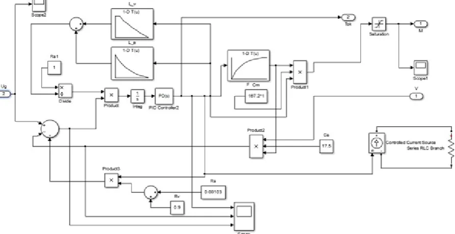
where 𝑈 - voltage on the traction motor; 𝐼 - current in the windings of the traction motor; e-counter-EMF induced in the armature winding; 𝑅𝑎, 𝑅𝑏 - respectively, the resistance of the armature windings and excitation; 𝐿𝑎, 𝐿𝑏 – respectively, the inductance of the armature winding and excitation winding. Taking into account (3) and (4) the model of traction motor [5] is developed, which describes dynamic electromagnetic processes in its circuits and takes into account the nature of loads, as well as the degree of saturation of the magnetic circuit when operating at different operating modes. The model is implemented in the application SIMULINK/MATLAB and is shown in Figure 1.
The model uses blocks to set the inductances of the armature "L-a", the winding "L-v" traction motor ЭДУ133 and its characteristic magnetization "F". In order to simulate dynamic processes in the power chain of the locomotive taking into account the conditions of the wheel and rail coupling in the application SIMULINK/MATLAB a comprehensive model of the system, shown in Figure 2, is developed.
The model-based solution of the traction issue is a differential equation of rotation of the armature of the traction motor: 𝐽𝑑
𝑑𝑡=𝑀 − 𝑀𝑟𝑒𝑠, where is the angular velocity of rotation of the armature of the traction motor; 𝑀𝑟𝑒𝑠 – the
moment of resistance on shaft of the traction motor; 𝐽 reduced moment of inertia of the moving train to the shaft of the traction motor. The moment of resistance and the moment of inertia were determined according to the data [6].
Mathematical model of microprocessor control system of technological processes (MCSTP) of locomotive is shown in Figure 3. Two large modules schematize the model of the locomotive, which differ from each other only in the block of tasks. The General model of the locomotive is includes a module of tasks, a power management module, voltage, model, traction motor, and the module of solving a dynamic issue.
Figure-2: Module of dynamic model of traction motor of direct current of consecutive excitation
SIMULATION RESULTS AND DISCUSSIONS
Figure-4: Simulation result of the voltage TED 2TE116UM and locomotives 2TE10MK
The results from the simulation of the traction motor is shown in Figure 4, where the voltage at increasing the position of the controller from the first to the maximum and then decreased back to the initial value.
As can be seen, the dependence of the voltage 2TE116UM from time to time has a higher derivative for low positions of the controller than 2TE10MK. However, due to the fact that the capacity of the locomotive 2TE116UM was reduced by 10% due to the peculiarities of operation in Central Asia (high maximum temperatures and low atmospheric pressure), the maximum value of the traction motor voltage is lower. The results of locomotive speed simulation are shown in Figure 5, as can be seen, despite the higher power, the locomotive 2TE10MK is characterized by less traction and, as a consequence, a slightly lower speed with an increase in position.
Figure-5: The result of modelling the speed of locomotives 2TE116UM and 2TE10MK with the change the position of
the driver controller.
From the above plot we can observe that locomotive 2TE10MK due to the greater number of positions of the controller, provides an increase in the voltage with some delay when compared to the locomotive 2TE116UM. For this reason, the growth of the current and speed of the traction motor begins with a delay. Therefore, the derivatives of the current and the time velocity (at low positions of the controller) 2TE10MK are noticeably lower, while its acceleration is higher. Nevertheless, from the data of table 1 it follows that the economic performance of the 2TE10MK locomotive (fuel and oil consumption, failure statistics) is more preferable than 2TE116UM.
REFERENCES
1. V. A. Prechisskiy, S. A. Martyshin. the Transmission of the locomotive with microprocessor control: a training manual for courses "Autonomous electric rolling stock"; Ministry of education and science of the Russian Federation, Federal Agency on education, Moscow energy Institute (Technical University). Moscow: Ed. MEI house 2008,. p. 67.
3. Grishchenko A. V., Grachev V. V., Kim S. I. etc. the Microprocessor system of automatic control of electric transmission locomotives: a tutorial for students of railway transport // under the editorship of A. V. Grishchenko. M.: The Route, 2004.
4. Schreiber M. M. a Simulation of the thermal state of traction motors of direct current // Bulletin of the results of scientific research. 2014. № 4 (13). p. 36-38.
5. Gordeev I. P., Tarasov E. M., Balalaev A. N., Calyculin A. N. Modeling of currents and voltages in power circuits of locomotives in various states of isolation // Bulletin of the Samara state. 2016. № 1 (31). p. 29-32. 6. Loginova E.Y, Gantumur Buren-Itgel Study of dynamic processes in the electric locomotive using Simulink /
MATLAB / / electronic journal Cloud of Science. 2015. T. 2. No. 1. URL: http://cloudofscience.ru. p. 87-97.
Source of support: Nil, Conflict of interest: None Declared.