User Guide
Wireless-G USB
Network Adapter
with SpeedBooster
COPYRIGHT & TRADEMARKS
Specifications are subject to change without notice. Linksys is a registered trademark or trademark of Cisco Systems, Inc. and/or its affiliates in the U.S. and certain other coun-tries. Copyright © 2003 Cisco Systems, Inc. All rights reserved. Other brands and prod-uct names are trademarks or registered trademarks of their respective holders.
LIMITED WARRANTY
Linksys guarantees that every Wireless-G USB Network Adapter will be free from physi-cal defects in material and workmanship for three years from the date of purchase, when used within the limits set forth in the Specifications section of this User Guide. If the prod-uct proves defective during this warranty period, call Linksys Technical Support in order to obtain a Return Authorization number. BE SURE TO HAVE YOUR PROOF OF PUR-CHASE ON HAND WHEN CALLING. When returning a product, mark the Return Authorization number clearly on the outside of the package and include a copy of your original proof of purchase. RETURN REQUESTS CANNOT BE PROCESSED WITHOUT PROOF OF PURCHASE. All customers located outside of the United States of America and Canada shall be held responsible for shipping and handling charges.
IN NO EVENT SHALL LINKSYS'S LIABILITY EXCEED THE PRICE PAID FOR THE PROD-UCT FROM DIRECT, INDIRECT, SPECIAL, INCIDENTAL, OR CONSEQUENTIAL DAM-AGES RESULTING FROM THE USE OF THE PRODUCT, ITS ACCOMPANYING SOFT-WARE, OR ITS DOCUMENTATION. LINKSYS OFFERS NO REFUNDS FOR ITS PROD-UCTS. Linksys makes no warranty or representation, expressed, implied, or statutory, with respect to its products or the contents or use of this documentation and all accom-panying software, and specifically disclaims its quality, performance, merchantability, or fitness for any particular purpose. Linksys reserves the right to revise or update its prod-ucts, software, or documentation without obligation to notify any individual or entity. Please direct all inquiries to:
Linksys P.O. Box 18558, Irvine, CA 92623.
SAFETY AND REGULATORY NOTICES
FCC STATEMENT
The Wireless-G USB Network Adapter has been tested and found to comply with the specifications for a Class B digital device, pursuant to Part 15 of the FCC Rules. Operation is subject to the following two conditions:
(1) This device may not cause harmful interference, and
(2) This device must accept any interference received, including interference that may cause undesired operation.
These limits are designed to provide reasonable protection against harmful interference in a residential installation. This equipment generates, uses, and can radiate radio fre-quency energy and, if not installed and used according to the instructions, may cause harmful interference to radio communications. However, there is no guarantee that inter-ference will not occur in a particular installation. If this equipment does cause harmful interference to radio or television reception, which is found by turning the equipment off and on, the user is encouraged to try to correct the interference by one or more of the following measures:
• Reorient or relocate the receiving antenna
• Increase the separation between the equipment or devices
• Connect the equipment to an outlet other than the receiver's
FCC Caution: Any change or modification to the product not expressly approved by Linksys could void the user's authority to operate the device.
FCC RF Radiation Exposure Statement
To comply with the FCC and ANSI C95.1 RF exposure limits, the antenna(s) for this
device must comply with the following: • Access points with 2.4 GHz integrated antenna must operate with a
sepa-ration distance of at least 20 cm from all persons using the cable provided and must not be co-located or operating in conjunction with any other antenna or transmitter. End-users must be provided with specific operations for satisfying RF exposu ance.
re
compli-Note: antennas used for diversity operation are not considered co-located.
Canadian Department of Communications Industry Canada (IC) Notice This Class B digital apparatus complies with Canadian ICES-003 and RSS-210. Cet appareil numérique de la classe B est conforme à la norme NMB-003 et CNR-210 du Canada.
"To prevent radio interference to the licensed service, this device is intended to be oper-ated indoors and away from windows to provide maximum shielding. Equipment (or its transmit antenna) that is installed outdoors is subject to licensing."
" Pour empêcher que cet appareil cause du brouillage au service faisant l'objet d'une licence, il doit être utilisé à l'intérieur et devrait être placé loin des fenêtres afin de fournir un écran de blindage maximal. Si le matériel (ou son antenne d'émission) est installé à l'extérieur, il doit faire l'objet d'une licence. "
EC DECLARATION OF CONFORMITY (EUROPE)
Linksys Group declares that the Instant Wireless®Series products included in the Instant Wireless®Series conform to the specifications listed below, following the provisions of the European R&TTE directive 1999/5/EC, EMC directive 89/336/EEC, and Low Voltage directive 73/23/EEC:
For 2.4 GHz devices with 100 mW radios, the following standards were applied: • ETS 300-826, 301 489-1 General EMC requirements for Radio equipment. • EN 609 50 Safety
• ETS 300-328-2 Technical requirements for Radio equipment.
Caution: This equipment is intended to be used in all EU and EFTA countries. Outdoor use may be restricted to certain frequencies and/or may require a license for operation.
Contact local Authority for pr ocedur e to follow .
Cisco-Linksys, LLC declares that WUSB54GS ( FCC
ID: Q87-WUSB54GS ) is limited in CH1~CH11 by specified
firmware controlled in U.S.A.
Note: Combinations of power levels and antennas resulting in a radiated power level of above 100 mW equivalent isotropic radiated power (EIRP) are considered as not com-pliant with the above mentioned directive and are not allowed for use within the European community and countries that have adopted the European R&TTE directive 1999/5/EC and/or the CEPT recommendation Rec 70.03.
For more details on legal combinations of power levels and antennas, contact Linksys Corporate Compliance.
• Linksys Group vakuuttaa täten että Wireless-G USB Network Adapter tyyppinen laite on direktiivin 1999/5/EY, direktiivin 89/336/EEC ja direktiivin 73/23/EEC oleellisten vaatimusten ja sitä koskevien näiden direktiivien muiden ehtojen mukainen. • Linksys Group déclare que la Wireless-G USB Network Adapter est conforme aux
conditions essentielles et aux dispositions relatives à la directive 1999/5/EC, la direc-tive 89/336/EEC, et à la direcdirec-tive 73/23/EEC.
• Belgique B L'utilisation en extérieur est autorisé sur le canal 11 (2462 MHz), 12 (2467 MHz), et 13 (2472 MHz). Dans le cas d'une utilisation privée, à l'extérieur d'un bâti-ment, au-dessus d'un espace public, aucun enregistrement n'est nécessaire pour une distance de moins de 300m. Pour une distance supérieure à 300m un enreg-istrement auprès de l'IBPT est requise. Pour une utilisation publique à l'extérieur de bâtiments, une licence de l'IBPT est requise. Pour les enregistrements et licences, veuillez contacter l'IBPT.
• France F:
2.4 GHz Bande : les canaux 10, 11, 12, 13 (2457, 2462, 2467, et 2472 MHz respec-tivement) sont complétement libres d'utilisation en France (en utilisation intérieur). Pour ce qui est des autres canaux, ils peuvent être soumis à autorisation selon le départment. L'utilisation en extérieur est soumis à autorisation préalable et très restreint.
2.4 GHz Band: only channels 10, 11, 12, 13 (2457, 2462, 2467, and 2472 MHz respectively) may be used freely in France for indoor use. License required for out-door installations.
• Deutschland D: Anmeldung im Outdoor-Bereich notwending, aber nicht genehmi-gungspflichtig. Bitte mit Händler die Vorgehensweise abstimmen.
• Germany D: License required for outdoor installations. Check with reseller for proce-dure to follow.
• Italia I: E' necessaria la concessione ministeriale anche per l'uso interno. Verificare con i rivenditori la procedura da seguire. L'uso per installazione in esterni non e' per-messa.
• Italy I: License required for indoor use. Use with outdoor installations not allowed. • The Netherlands NL License required for outdoor installations. Check with reseller for
procedure to follow.
• Nederlands NL Licentie verplicht voor gebruik met buitenantennes. Neem contact op met verkoper voor juiste procedure.
WUSB54G-UG-3015A KL
Table of Contents
Chapter 1: Introduction 1
The Wireless-G USB Network Adapter 1
Features 1
Chapter 2: Planning Your Wireless Network 2
Network Topology 2
Ad-Hoc versus Infrastructure Mode 2
Chapter 3: Getting to Know the
Wireless-G USB Network Adapter 4
The Adapter’s Ports 4
The Adapter’s LEDs 4
Chapter 4: Software Installation
and Configuration for Windows 2000 5
Chapter 5: Hardware Installation 9
Connecting the Adapter 9
Chapter 6: Driver Installation for Windows XP 11
Windows XP Wireless Zero Configuration 12
Chapter 7: Using the WLAN Monitor 14
Overview 14
Accessing the WLAN Monitor 14
Link Information 15
Site Survey 17
Profiles 18
Chapter 1: Introduction
Connect your USB-equipped desktop or notebook computer to a wireless net-work at incredible speeds with the Linksys Wireless-G USB Netnet-work Adapter. By incorporating two new, blazing fast technologies -- USB 2.0 and Wireless-G -- the Adapter delivers data rates up to 54Mbps (5 times as fast as 802.11b), without the trouble of opening up the case of your desktop computer.
To install, simply plug the Adapter into any available USB port. (It's compati-ble with both USB 1.1 and 2.0 ports, but 2.0 will yield the fastest speeds.) It gets its power through the USB connection, so no power cord is necessary. The included Setup Wizard walks you through configuring the Adapter to your wireless network settings, step by step. The Wireless-G USB Network Adapter is also compatible with the Wireless-B (802.11b) network standard, with data rates up to 11Mbps. And your wireless communications can be protected by 128-bit encryption, so your data stays secure.
The Wireless-G USB Network Adapter's high-gain antenna lets you put your computer almost anywhere in the building, without the cost and hassle of run-ning cables. Now you don't have to drill holes in your walls and climb through the attic or cellar to get connected to the network. Once you're connected, you can keep in touch with your e-mail, access the Internet, use instant messaging to chat with friends, and share files and other resources such as printers and hard disk storage space with other computers on the network.
So don't hassle with running cables through your house -- get connected the easy way with the Wireless-G USB Network Adapter.
• Compatible with 802.11g and 802.11b (2.4GHz) Stardards
• Support USB 2.0 with up to 54Mbps, High-Speed Data Transfer Rate with Automatic Fallback
• Plug-and-Play Operation Provides Easy Setup • Supports up to 128-bit WEP Encryption Security • Compatible with Microsoft Windows 2000 and XP
Appendix A: Troubleshooting 26
Common Problems and Solutions 26 Frequently Asked Questions 27
Appendix B: Glossary 30
Appendix C: Specifications 38
Environmental 39
Appendix D: Warranty Information 40
Appendix E: Contact Information 41
The Wireless-G USB Network Adapter
If the wireless network is relatively small and needs to share resources only with the other computers on the wireless network, then the ad-hoc mode can be used. (See Figure 2-2.) Ad-hoc mode allows computers equipped with wire-less transmitters and receivers to communicate directly with each other, elimi-nating the need for an access point. The drawback of this mode is that, in Ad-Hoc mode, wireless-equipped computers are not able to communicate with computers on a wired network. And, of course, communication between the wireless-equipped computers is limited by the distance and interference direct-ly between them.
Figure 2-2
Chapter 2: Planning Your Wireless
Network
A wireless local area network (WLAN) is exactly like a regular local area net-work (LAN), except that each computer in the WLAN uses a wireless device to connect to the network. Computers in a WLAN share the same frequency channel and SSID, which is an identification name for wireless devices.
Unlike wired networks, wireless networks have two different modes in which they may be set up: infrastructureand ad-hoc. An infrastructure configura-tion is a WLAN and wired LAN communicating to each other through an access point. An ad-hoc configuration is wireless-equipped computers com-municating directly with each other. Choosing between these two modes depends on whether or not the wireless network needs to share data or periph-erals with a wired network or not.
If the computers on the wireless network need to be accessed by a wired network or need to share a peripheral, such as a print-er, with the wired network computers, the wireless network should be set up in infrastructure mode. (See Figure 2-1.) The basis of infrastructure mode centers around an access point, which serves
as the main point of communications in a wireless network. Access points transmit data to PCs equipped with wireless network cards, which can roam within a certain radial range of the access point. Multiple access points can be arranged to work in succession to extend the roaming range, and can be set up to communicate with your Ethernet (wired) hardware as well.
Network Topology
Ad-Hoc versus Infrastructure Mode
Chapter 4: Software Installation and
Configuration for Windows 2000
The Wireless-G USB Network Adapter Setup Wizard will guide you through the installation procedure. The Setup Wizard will install the WLAN Monitor and driver, as well as configure the Adapter.
1. Insert the Setup Wizard CD-ROM into your CD-ROM drive. The Setup Wizard should run automatically, and Figure 4-1 should appear. If it does not, click the Start button and choose Run. In the field that appears, enter
D:\setup.exe(if “D” is the letter of your CD-ROM drive).
To install the Adapter, click the Installbutton on theWelcomescreen. Click
User Guideto view this User Guide or click Exitto exit the Setup Wizard. Figure 4-1
Important:You must run the Setup Wizard to install the software before connecting the Adapter.
Chapter 3: Getting to Know the
Wireless-G USB Network Adapter
The Network Adapter is connected to your PC through its USB port. All power is provided through the USB connection, making a power adapter unnecessary.
The Network Adapter’s LEDs show you how the Adapter is functioning.
Power Green. This LED will light up to let you know that the Adapter is adequately powered over the USB connection.
Link Green. The Link LED will be lit steadily when the Network Adapter is connected to your wireless network. The LED will blink when there is wireless network traffic.
The USB Port
4. If you chose I n f r a s t r u c t u r e Mode, go to Step 5 now. If you chose Ad-Hoc Mode, select the correct operating channel for your network from the Channel drop-down menu. Then, select the Network Mode from the drop-down menu. Click the Next
button, and go to Step 5. Click the Backbutton to change any settings.
Channel - The channel you choose should match the channel set on the other devices in your wireless network. If you are unsure about which chan-nel to use, select the default chanchan-nel (Chanchan-nel 6).
Network Mode - Keep the default setting, Mixed, if you have Wireless-G and Wireless-B devices in your network. Select G-Onlyif you have only Wireless-G devices in your network.
5. The Setup Wizard will ask you to review your set-tings before it starts to copy files. Click the
Next button to save these set-tings, or click the
Back button to change any set-tings.
Figure 4-4
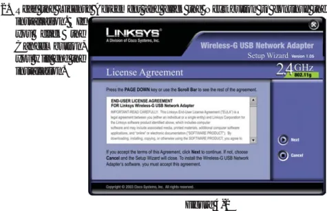
Figure 4-5 2. Read the License Agreement and click the Next button to continue the
installation. If you click the
Cancel button, you will end the installation.
3. The following screen, shown in Figure 4-3, will ask for some information about your wireless network. In the SSIDfield, enter your network’s SSID
(Service Set Identifier). The SSID is your network name and must be iden-tical for all devices in the network. The default setting is linksys (all low-ercase).
Next, choose a wireless mode. Click the Infrastructure Moderadio button if you want your wireless computers to network with computers on your wired network using a wireless access point. Click the Ad-Hoc Moderadio button if you
want multiple wireless com-puters to net-work directly with each other. Click the Next
button to contin-ue, or click the
Back button to return to the previous page.
Figure 4-2
6. At this point, you may see a warn-ing screen, such as that shown in Figure 4-6 , asking if you’d like to cease installation. You can click the Yes button to continue; the Adapter will function properly.
7. After the files have been successfully copied, the screen in Figure 4-7 will appear. Click the Exitbutton.
Proceed to “Chapter 5: Hardware Installation.”
Figure 4-6
Figure 4-7
Chapter 5: Hardware Installation
1. The Adapter comes with the USB cable you will use to connect the Adapter to your PC. (See Figure 5-1.)
2. Connect one end of the USB cable to the USB port of the Adapter.
3. Connect the other end of the USB cable to one of the USB ports on your computer (see Figure 5-2).
Figure 5-1
Figure 5-2
Connecting the Adapter
Wireless-G USB Network Adapter
Important for Windows 2000 users:You must run the Setup Wizard to install the software before installing the hardware.
Important for Windows XP users:You must install the Adapter’s hardware before installing the software.
Chapter 6: Driver Installation for
Windows XP
After connecting the Adapter to your PC, as shown in Chapter 5, you’ll need to install the driver. 1. Windows XP will
automati-cally detect the Adapter. Insert the Setup CD-ROM into the CD-ROM drive. Click the radio button next to
Install the software auto-matically (Recommended)
(as shown in Figure 6-1). Then click the Next button. 2. A screen similar to that shown in
Figure 6-2 will appear, asking if you wish to discontinue installa-tion. This software has been test-ed and found to work properly with Windows XP. Click the
Continue Anyway button to continue installation.
3. The next screen shows that the Wizard is complete. Click the
Finish button. The drivers are now installed.
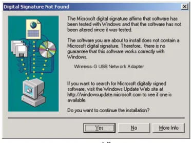
4. When Windows 2000 begins installing the Network Adapter’s driver file, a screen similar to that shown in Figure 5-3 will appear, stating that a digital signature was not found. This software has been tested and found to work properly with Windows 2000. Click the Yesbutton to continue installation.
If your PC is running Windows XP, proceed to “Chapter 6: Driver Installation for Windows XP.”
If your PC is running Windows 2000, the installation of the Wireless-B USB Network Adapter is complete. If you want to check the link
informa-tion, search for available wireless networks, or make additional configu-ration changes, proceed to “Chapter 7: Using the WLAN Monitor.”
Figure 5-3
Figure 6-2 Figure 6-1
3. If WEP is enabled, the screen in Figure 6-6 will appear. Enter the WEP key of your wireless network in the Network key field, and re-enter it in the Confirm network keyfield. Then click the Connect button, and go to step 4.
4. The screen in Figure 6-7 will appear if your connection is active.
For more information about wireless networking on a Windows XP computer, click Start and then Help and Support. Enter the keyword wireless in the field provided, and press the Enterkey.
Congratulations! The installation of the Wireless-G USB Network Adapter is complete.
1. After installing the Adapter, the Windows XP Wireless Zero Configuration icon will appear in your comput-er’s system tray (see Figure 6-4). Double-click the icon.
2. The screen that appears will show any available wireless network. Select the network you want.
If this network has WEP encryption enabled, go to step 3.
If this network does not have WEP encryption enabled, then Figure 6-5 will appear. Make sure the box next to Allow me to connect to the selected wireless network, even though it is not secure is checked. Then click the
Connect button, and go to step 4.
Windows XP Wireless Zero Configuration
Note for Windows XP users:Windows XP has a built-in configura-tion tool. Use Windows XP Wireless Zero Configuraconfigura-tion (in the sys-tem tray at the bottom of your screen) to configure the Adapter.
Figure 6-4
Figure 6-6
Note:Steps 2 and 3 are the instructions and screenshots for Windows XP with Service Pack 1 installed.
If you have not installed Service Pack 1, select the network you want, and click the Connect button. If the network has WEP encryption enabled, enter the WEP key in the Network keyfield, and then click the Connectbutton.
Note: Windows XP Wireless Zero Configuration does not support the use of a passphrase. Enter the exact WEP key used by your access point.
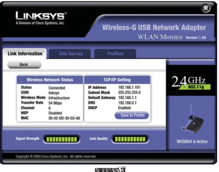
The Link Informationscreen, shown again in Figure 7-3, displays the signal strength and link quality information about the current connection and provides a button to click for additional status information.
Ad-Hoc Mode or Infrastructure Mode - The screen indicates whether the Adapter is currently working in ad-hoc or infrastructure mode.
Signal Strength- The Signal Strength bar indicates the signal strength.
Link Quality- The Link Quality bar indicates the quality of the wireless net-work connection.
Click the More Informationbutton to view more information about the wire-less network connection, shown on the following page and in Figure 7-4.. Click the X (Close) button in the upper right corner to exit the WLAN Monitor.
Link Information
Figure 7-3
Chapter 7: Using the WLAN Monitor
Use the WLAN Monitor to check the link information, search for available wireless networks, or create profiles that hold different configuration settings.
After installing the Adapter, the Wireless-G USB Network Adapter WLAN Monitor icon will appear in your system tray. Double-click the icon (see Figure 7-1).
The Link Informationscreen will appear. (See Figure 7-2.) From this screen, you can find out how strong the current wireless signal is and how good the connection’s quality is. You can also click the More Information button to view additional status information about the current wireless connection. To search for available wireless networks, click the Site Surveytab. To
per-form configuration changes, click the Profilestab. Figure 7-1
Figure 7-2
Accessing the WLAN Monitor Overview
The Site Surveyscreen, shown in Figure 7-5, displays a list of infrastructure and ad-hoc networks available for connection.
SSID- The SSID or unique name of the wireless network.
Signal- The percentage of signal strength, from 0 to 100%.
Site Information
Wireless Mode- The mode of the wireless network currently in use.
Channel- The channel to which the wireless network devices are set.
WEP- The status of the WEP encryption security feature.
MAC- The MAC address of the wireless network’s access point.
Surveyed at - The time at which the wireless network was scanned.
Refresh - Click the Refresh button to perform a new search for wireless devices.
Connect- To connect to one of the networks on the list, select the wireless net-work,and click the Connectbutton. If the wireless network has WEP encryp-tion enabled, you will see the screen shown in Figure 7-6.
Figure 7-5
Site Survey
Wireless Network Status
Status- The status of the wireless network connection.
SSID- The unique name of the wireless network.
Wireless Mode- The mode of the wireless network currently in use.
Transfer Rate- The data transfer rate of the current connection.
Channel- The channel to which the wireless network devices are set.
WEP- The status of the WEP encryption security feature.
MAC- The MAC address of the wireless network’s access point.
TCP/IP Setting
IP Address- The IP Address of the Adapter.
Subnet Mask- The Subnet Mask of the Adapter.
Default Gateway- The Default Gateway address of the Adapter.
DNS- The DNS address of the Adapter.
DHCP- The status of the DHCP client.
Signal Strength- The Signal Strength bar indicates the signal strength.
Link Quality- The Link Quality bar indicates the quality of the wireless net-work connection.
Import- Click the
Import button to import a profile that has been saved in another location. Select the appropri-ate file, as shown in Figure 7-7, and click the Open but-ton.
Export - To save the profile(s) in a different location, click the Export
button. Direct Windows to the appropriate folder, as shown in Figure 7-8, and click the
OKbutton.
Delete - Click the Deletebutton to delete a profile.
Click the X (Close) button in the upper right corner to exit the WLAN Monitor. Figure 7-7
Figure 7-8
Note:If you have more than one profile, you must Export them in order to keep them saved.
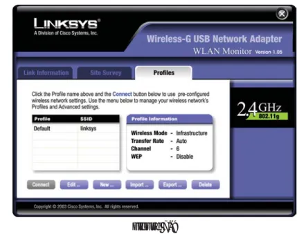
The Profiles screen, shown in Figure 7-6, lets you save different configuration profiles for different network setups. You can also import or export profiles. The default profile holds the initial configuration saved when you ran the Setup Wizard.
Profile- Name of the connection profile.
SSID- The wireless network’s unique name, as set in the connection profile.
Profile Information
Wireless Mode- The mode of the wireless network currently in use.
Transfer Rate - The data transfer rate of the current connection. (In Auto mode, the Adapter dynamically shifts to the fastest data transfer rate possible at any given time.)
Channel- The channel to which the wireless network devices are set.
WEP- The status of the WEP encryption security feature.
Connect- To connect to a wireless network using a specific profile, select the profile,and click the Connectbutton.
Edit- Select a profile, and click the Editbutton to change an existing profile.
New - Click the New button to create a new profile. See the next section, “Creating a New Profile,” for detailed instructions.
Figure 7-6
3. The Network Settingscreen, shown in Figure 7-11, will appear.
If your network has a DHCP server (or Router), click the radio button next to Obtain an IP address automatically (DHCP)and click the Next but-ton to continue.
If your network does not have a DHCP server (or router), click the radio button next to Specify the IP address. Enter an IP Address, Subnet Mask,
Default Gateway, and DNS appropriate for your network. Enter each address in this format: xxx.xxx.xxx.xxx (the x’s represent the numbers that make up each address). You must specify the IP Address and Subnet Mask on this screen. If you are unsure about the Default Gateway and DNS addresses, then leave these fields alone.
Click the Nextbutton to continue or the Cancelbutton to return to the pre-vious screen.
IP Address - This IP Address must be unique to your network.
Subnet Mask - The Adapter’s Subnet Mask must be the same as your wired network’s Subnet Mask.
Default Gateway - Enter the IP address of your network’s Gateway here.
DNS - Enter the DNS addresses of your network here. 1. On the Profilesscreen, shown again in Figure 7-9, click the Newbutton to
create a new profile.
2. When the Create connection profilescreen appears, enter a name for the new profile. Click OKto save the profile name or click Cancelto return to the previous screen.
Figure 7-10
Creating a New Profile
5. The Ad-Hoc Mode Settingsscreen, for those who chose an Ad-hoc network, will appear. Select the correct operating channel for your network from the Channel drop-down menu. Then, select the Network Mode from the drop-down menu. Click the Nextbutton to continue or click the Backbutton to change any settings.
Channel - The channel you choose should match the channel set on the other devices in your wireless network. If you are unsure about which chan-nel to use, select the default chanchan-nel (Chanchan-nel 6).
Network Mode- Select Mixed Mode, and both G and Wireless-B computers will be allowed on the network, but the speed will be reduced. Select G-Only Modefor maximum speed, but no Wireless-B users will be allowed on the network.
6. The Security Settingsscreen, shown in Figure 7-14, will appear. Enable or disable Wired Equivalent Privacy (WEP) encryption for your wireless net-work. If you enable WEP, enter a Passphrase or WEP key. Click the Next
button to continue or the Backbutton to return to the previous screen. 4. The Wireless Modescreen, shown in Figure 7-12, shows a choice of two
wireless modes. Click the Infrastructure Moderadio button if you want your wireless computers to communicate with computers on your wired network via a wireless access point. Click the Ad-Hoc Moderadio button if you want multiple wireless computers to communicate directly with each other. Click the Nextbutton to continue or the Backbutton to return to the previous screen.
SSID- The SSID is the unique name shared among all devices in your wire-less network. The SSID must be identical for all devices in the wirewire-less net-work. It is case-sensitive and must not exceed 32 alphanumeric characters, which can be any keyboard character.
Infrastructure Mode - This mode allows wireless and wired networks to communicate through an access point.
Ad-Hoc Mode - This mode allows wireless-equipped computers to com-municate directly with each other. No access point is used.
Figure 7-13
WEP (Disabled/64-bit WEP/128-bit WEP) - If you do not want to use WEP encryption, choose Disabled. To use WEP encryption (recommended to increase network security), select 64-bitor 128-bit WEPfrom the drop-down menu, and enter either a Passphrase or WEP key.
Passphrase - Instead of manually entering WEP keys, you can enter a Passphrase, so that a WEP key is automatically generated. It is case-sensi-tive and should not be longer than 16 alphanumeric characters. This passphrase must match the passphrase of your wireless network and is com-patible with other Linksys wireless products only. (If you have any non-Linksys wireless products, enter the WEP key(s) manually on those prod-ucts.)
WEP Key - This WEP key must match the WEP key of your wireless net-work. If you are using 64-bit WEP encryption, then the key must consist of exactly ten hexadecimal characters. If you are using 128-bit WEP encryp-tion, then the key must consist of exactly 26 hexadecimal characters. Valid hexadecimal characters are “0” to “9” and “A” to “F”.
TX Key - This allows you to access different WEP keys used by different routers or access points in your network. Choose the TX Key used in that network. For instance, if the device uses TX Key 3, use TX Key 3. If you’re not using multiple WEP Keys, leave this set at 1.
7. The Confirm New Settingsscreen will appear (shown in Figure 7-15). To save the new settings, click the Yesbutton. To cancel the settings and return to the
P r o f i l e s screen, click the Cancel
button. To edit the new s e t t i n g s , click the
Back but-ton.
8. The Congratulations screen (Figure 7-16) will appear next. Click Activate new settings nowto implement the new settings immediately and return to the Link Informationscreen. Click Activate new settings laterto keep the current settings active, and return to the Profilesscreen so that you can edit your profile
or create another pro-file.
You have successfully created a connection profile. Click the X (Close)
but-Figure 7-15
Can I run an application from a remote computer over the wireless network?
This will depend on whether or not the application is designed to be used over a network. Consult the application’s user guide to determine if it supports operation over a network.
Can I play computer games with other members of the wireless network?
Yes, as long as the game supports multiple players over a LAN (local area net-work). Refer to the game’s user guide for more information.
What is the IEEE 802.11b standard?
It is one of the IEEE standards for wireless networks. The 802.11b standard allows wireless networking hardware from different manufacturers to communicate, pro-vided that the hardware complies with the 802.11b standard. The 802.11b standard states a maximum data transfer rate of 11Mbps and an operating frequency of 2.4GHz.
What IEEE 802.11b features are supported?
The product supports the following IEEE 802.11b functions: • CSMA/CA plus Acknowledge protocol
• Multi-Channel Roaming • Automatic Rate Selection • RTS/CTS feature • Fragmentation • Power Management
What is ad-hoc mode?
When a wireless network is set to ad-hoc mode, the wireless-equipped computers are configured to communicate directly with each other. The ad-hoc wireless net-work will not communicate with any wired netnet-work.
What is infrastructure mode?
When a wireless network is set to infrastructure mode, the wireless network is configured to communicate with a wired network through a wireless access point.
What is roaming?
Roaming is the ability of a portable computer user to communicate continuously while moving freely throughout an area greater than that covered by a single access point. Before using the roaming function, the workstation must make sure that it is the same channel number with the access point of dedicated coverage area.
Appendix A: Troubleshooting
This chapter provides solutions to problems that may occur during the installa-tion and operainstalla-tion of the Wireless-G USB Network Adapter. Read the descrip-tions below to solve your problems. If you can’t find an answer here, check the Linksys website at www.linksys.com.
1. My computer does not recognize the USB Network Adapter.
• Make sure that the USB Network Adapter is properly inserted into the USB port.
• Also, make sure that the USB Controller is enabled in the BIOS. Check with your motherboard User Guide for more information.
2. The USB Network Adapter does not work properly.
• Reinsert the USB Network Adapter into the notebook or desktop’s USB port. • Right-click on My Computer, and select Properties. Select the Adapter,
then chose the Device Managertab, and click on the Network Adapter. You will find the USB Network Adapter if it is installed successfully. If you see a yellow exclamation mark, the resources may be conflicting and you must follow the steps below:
• Uninstall the driver software from your PC.
• Restart your PC and repeat the hardware and software installation as specified in this User Guide.
3. I cannot communicate with the other computers linked via Ethernet in the Infrastructure configuration.
• Make sure that the notebook or desktop is powered on.
• Make sure that your USB Network Adapter is configured on the same chan-nel, SSID, and WEP as the other computers in the Infrastructure configura-tion.
Frequently Asked Questions
Direct-Sequence Spread-Spectrum (DSSS) generates a redundant bit pattern for each bit to be transmitted. This bit pattern is called a chip (or chipping code). The longer the chip, the greater the probability that the original data can be recovered. Even if one or more bits in the chip are damaged during trans-mission, statistical techniques embedded in the radio can recover the original data without the need for retransmission. To an unintended receiver, DSSS appears as low power wideband noise and is rejected (ignored) by most nar-rowband receivers.
Would the information be intercepted while transmitting on air?
WLAN features two-fold protection in security. On the hardware side, as with Direct Sequence Spread Spectrum technology, it has the inherent security fea-ture of scrambling. On the software side, WLAN offers the encryption function (WEP) to enhance security and access control.
What is WEP?
WEP is Wired Equivalent Privacy, a data privacy mechanism based on a 64-bit or 128-bit shared key algorithm, as described in the IEEE 802.11 standard. To achieve true seamless connectivity, the wireless LAN must incorporate a
number of different functions. Each node and access point, for example, must always acknowledge receipt of each message. Each node must maintain contact with the wireless network even when not actually transmitting data. Achieving these functions simultaneously requires a dynamic RF networking technology that links access points and nodes. In such a system, the user’s end node under-takes a search for the best possible access to the system. First, it evaluates such factors as signal strength and quality, as well as the message load currently being carried by each access point and the distance of each access point to the wired backbone. Based on that information, the node next selects the right access point and registers its address. Communications between end node and host computer can then be transmitted up and down the backbone.
As the user moves on, the end node’s RF transmitter regularly checks the sys-tem to determine whether it is in touch with the original access point or whether it should seek a new one. When a node no longer receives acknowledgment from its original access point, it undertakes a new search. Upon finding a new access point, it then re-registers, and the communication process continues.
What is ISM band?
The FCC and their counterparts outside of the U.S. have set aside bandwidth for unlicensed use in the ISM (Industrial, Scientific and Medical) band. Spectrum in the vicinity of 2.4 GHz, in particular, is being made available worldwide. This presents a truly revolutionary opportunity to place convenient high-speed wireless capabilities in the hands of users around the globe.
What is Spread Spectrum?
Spread Spectrum technology is a wideband radio frequency technique devel-oped by the military for use in reliable, secure, mission-critical communica-tions systems. It is designed to trade off bandwidth efficiency for reliability, integrity, and security. In other words, more bandwidth is consumed than in the case of narrowband transmission, but the trade-off produces a signal that is, in effect, louder and thus easier to detect, provided that the receiver knows the parameters of the spread-spectrum signal being broadcast. If a receiver is not tuned to the right frequency, a spread-spectrum signal looks like background noise. There are two main alternatives, Direct Sequence Spread Spectrum (DSSS) and Frequency Hopping Spread Spectrum (FHSS).
What is DSSS? What is FHSS? And what are their differences?
Frequency-Hopping Spread-Spectrum (FHSS) uses a narrowband carrier that changes frequency in a pattern that is known to both transmitter and receiver. Properly synchronized, the net effect is to maintain a single logical channel. To
Bit- A binary digit. The value - 0 or 1-used in the binary numbering system. Also, the smallest form of data.
CSMA/CA(Carrier Sense Multiple Access/Collision Avoidance) - In local area networking, this is the CSMA technique that combines slotted time-divi-sion multiplexing with carrier sense multiple access/collitime-divi-sion detection (CSMA/CD) to avoid having collisions occur a second time. This works best if the time allocated is short compared to packet length and if the number of sit-uations is small.
CSMA/CD (Carrier Sense Multiple Access/Collision Detection) - The LAN access method used in Ethernet. When a device wants to gain access to the net-work, it checks to see if the network is quiet (senses the carrier). If it is not, it waits a random amount of time before retrying. If the network is quiet and two devices access the line at exactly the same time, their signals collide. When the collision is detected, they both back off and each wait a random amount of time before retrying.
CTS(Clear To Send) - An RS-232 signal sent from the receiving station to the transmitting station that indicates it is ready to accept data.
Default Gateway - The routing device used to forward all traffic that is not addressed to a station within the local subnet.
DHCP(Dynamic Host Configuration Protocol) - A protocol that lets network administrators manage centrally and automate the assignment of Internet Protocol (IP) addresses in an organization's network. Using the Internet's set of protocol (TCP/IP), each machine that can connect to the Internet needs a unique IP address. When an organization sets up its computer users with a con-nection to the Internet, an IP address must be assigned to each machine. Without DHCP, the IP address must be entered manually at each computer and, if computers move to another location in another part of the network, a new IP address must be entered. DHCP lets a network administrator supervise and dis-tribute IP addresses from a central point and automatically sends a new IP address when a computer is plugged into a different place in the network. DHCP uses the concept of a "lease" or amount of time that a given IP address will be valid for a computer. The lease time can vary depending on how long a user is likely to require the Internet connection at a particular location. It's espe-cially useful in education and other environments where users change fre-quently. Using very short leases, DHCP can dynamically reconfigure networks in which there are more computers than there are available IP addresses.
Appendix B: Glossary
802.11b - One of the IEEE standards for wireless networking hardware. Products that adhere to a specific IEEE standard will work with each other, even if they are manufactured by different companies. The 802.11b standard specifies a maximum data transfer rate of 11Mbps, an operating frequency of 2.4GHz, and WEP encryption for security. 802.11b networks are also referred to as Wi-Fi networks.
802.11g- A proposed, but as yet unratified extension of the IEEE 802.11 stan-dard for wireless networking hardware. The draft 802.11g specifications used by Linksys specify a maximum data transfer rate of 54Mbps using OFDM modulation, an operating frequency of 2.4GHz, backward compatibility with IEEE 802.11b devices, and WEP encryption for security.
Adapter - Printed circuit board that plugs into a PC to add to capabilities or connectivity to a PC. In a networked environment, a network interface card is the typical adapter that allows the PC or server to connect to the intranet and/or Internet.
Ad-hoc Network- An ad-hoc network is a group of computers, each with a wireless adapter, connected as an independent 802.11 wireless LAN. Ad-hoc wireless computers operate on a peer-to-peer basis, communicating directly with each other without the use of an access point. Ad-hoc mode is also referred to as an Independent Basic Service Set or as peer-to-peer mode.
Automatic Fall-back - A feature provided by some wireless products to increase connection reliability. Automatic fall-back enables a device to dynam-ically shift between various data transfer rates. It works by decreasing the data transfer rate when interference increases, distance increases, and other factors undermine signal strength and quality.
Backbone- The part of a network that connects most of the systems and net-works together and handles the most data.
Bandwidth - The transmission capacity of a given facility, in terms of how much data the facility can transmit in a fixed amount of time; expressed in bits per second (bps).
Fragmentation- Breaking a packet into smaller units when transmitting over a network medium that cannot support the original size of the packet.
Gateway- A device that interconnects networks with different, incompatible communications protocols.
Hardware - Hardware is the physical aspect of computers, telecommunica-tions, and other information technology devices. The term arose as a way to dis-tinguish the "box" and the electronic circuitry and components of a computer from the program you put in it to make it do things. The program came to be known as the software.
Hop- The link between two network nodes.
IEEE (The Institute of Electrical and Electronics Engineers) - The IEEE describes itself as "the world's largest technical professional society, promoting the development and application of electrotechnology and allied sciences for the benefit of humanity, the advancement of the profession, and the well-being of our members."
The IEEE fosters the development of standards that often become national and international standards. The organization publishes a number of journals, has many local chapters, and several large societies in special areas, such as the IEEE Computer Society.
Infrastructure Network- An infrastructure network is a group of computers or other devices, each with a wireless adapter, connected as an 802.11 wireless LAN. In infrastructure mode, the wireless devices communicate with each other and to a wired network by first going through an access point. An infra-structure wireless network connected to a wired network is referred to as a Basic Service Set. A set of two or more BSS in a single network is referred to as an Extended Service Set. Infrastructure mode is useful at a corporation scale, or when it is necessary to connect the wired and wireless networks.
IP(Internet Protocol) - The method or protocol by which data is sent from one computer to another on the Internet. It is a standard set of rules, procedures, or conventions relating to the format and timing of data transmission between two computers that they must accept and use to be able to understand each other.
IP Address - In the most widely installed level of the Internet Protocol (IP) today, an IP address is a 32-binary digit number that identifies each sender or DHCP supports static addresses for computers containing Web servers that
need a permanent IP address.
DNS- The domain name system (DNS) is the way that Internet domain name are located and translated into Internet Protocol (IP) addresses. A domain name is a meaningful and easy-to-remember "handle" for an Internet address.
Domain- A subnetwork comprised of a group of clients and servers under the control of one security database. Dividing LANs into domains improves per-formance and security.
Driver - A workstation or server software module that provides an interface between a network interface card and the upper-layer protocol software running in the computer; it is designed for a specific device, and is installed during the initial installation of a network-compatible client or server operating system.
DSSS(Direct-Sequence Spread Spectrum) - DSSS generates a redundant bit pattern for all data transmitted. This bit pattern is called a chip (or chipping code). Even if one or more bits in the chip are damaged during transmission, statistical techniques embedded in the receiver can recover the original data without the need for retransmission. To an unintended receiver, DSSS appears as low power wideband noise and is rejected (ignored) by most narrowband receivers. However, to an intended receiver (i.e. another wireless LAN end-point), the DSSS signal is recognized as the only valid signal, and interference is inherently rejected (ignored).
Encryption - A security method that applies a specific algorithm to data in order to alter the data's appearance and prevent other devices from reading the information.
Ethernet - IEEE standard network protocol that specifies how data is placed on and retrieved from a common transmission medium. Has a transfer rate of 10 Mbps. Forms the underlying transport vehicle used by several upper-level protocols, including TCP/IP and XNS.
FHSS(Frequency Hopping Spread Spectrum) - FHSS continuously changes (hops) the carrier frequency of a conventional carrier several times per second according to a pseudo-random set of channels. Because a fixed frequency is not used, and only the transmitter and receiver know the hop patterns, interception of FHSS is extremely difficult.
OFDM- Developed for wireless applications, Orthogonal Frequency Division Multiplexing (OFDM) technology offers superior performance--increased data rates and more reliable transmissions--than previous technologies, such as DSSS. OFDM is a scheme in which numerous signals of different frequencies are combined to form a single signal for transmission on the medium. OFDM works by breaking one high-speed data stream into a number of lower-speed data streams, which are then transmitted in parallel. Each lower lower-speed stream is used to modulate a subcarrier. Essentially, this creates a multi-carrier transmission by dividing a wide frequency band or channel into a number of narrower frequency bands or sub-channels. OFDM is also used for other appli-cations, including powerline networking.
Packet- A unit of data routed between an origin and a destination in a network. Packet Filtering - Discarding unwanted network traffic based on its originating address or range of addresses or its type (e-mail, file transfer, etc.).
Passphrase- Used much like a password, a passphrase simplifies the WEP encryption process by automatically generating the WEP encryption keys for Linksys products.
Plug-and-Play - The ability of a computer system to configure expansion boards and other devices automatically without requiring the user to turn off the system during installation.
Port- A pathway into and out of the computer or a network device. For exam-ple, the serial and parallel ports on a personal computer are external sockets for plugging in communications lines, modems and printers.
Roaming- In an infrastructure mode wireless network, this refers to the abili-ty to move out of one access point's range and into another and transparently reassociate and reauthenticate to the new access point. This reassociation and reauthentication should occur without user intervention and ideally without interruption to network connectivity. A typical scenario would be a location with multiple access points, where users can physically relocate from one area to another and easily maintain connectivity.
RTS(Request To Send) - An RS-232 signal sent from the transmitting station to the receiving station requesting permission to transmit.
request an HTML page or send e-mail, the Internet Protocol part of TCP/IP includes your IP address in the message (actually, in each of the packets if more than one is required) and sends it to the IP address that is obtained by looking up the domain name in the Uniform Resource Locator you requested or in the e-mail address you're sending a note to. At the other end, the recipient can see the IP address of the Web page requestor or the e-mail sender and can respond by sending another message using the IP address it received.
ISM band- The FCC and their counterparts outside of the U.S. have set aside bandwidth for unlicensed use in the ISM (Industrial, Scientific and Medical) band. Spectrum in the vicinity of 2.4 GHz, in particular, is being made avail-able worldwide. This presents a truly revolutionary opportunity to place con-venient high-speed wireless capabilities in the hands of users around the globe.
LAN(Local Area Network) - A group of computers and associated devices that share a common communications line and typically share the resources of a single processor or server within a small geographic area (for example, within an office building).
MAC (Media Access Control) Address- A unique number assigned by the manufacturer to any Ethernet networking device, such as a network adapter, that allows the network to identify it at the hardware level.
Mbps(Megabits per second) - One million bits per second; unit of measure-ment for data transmission.
Motherboard- A motherboard is the physical arrangement in a computer that contains the computer's basic circuitry and components.
Network- A system that transmits any combination of voice, video and/or data between users.
Node- A network junction or connection point, typically a computer or work station.
Notebook (PC)- A notebook computer is a battery-powered personal comput-er gencomput-erally smallcomput-er than a briefcase that can easily be transported and conve-niently used in temporary spaces such as on airplanes, in libraries, temporary offices, and at meetings. A notebook computer, sometimes called a laptop com-puter, typically weighs less than five pounds and is three inches or less in thick-ness.
of the data (routing), TCP takes care of keeping track of the individual units of data (called packets) that a message is divided into for efficient delivery over the network. TCP is known as a "connection oriented" protocol due to requir-ing the receiver of a packet to return an acknowledgment of receipt to the sender of the packet resulting in transmission control.
TCP/IP(Transmission Control Protocol/Internet Protocol) - The basic com-munication language or set of protocols for comcom-munications over a network (developed specifically for the Internet). TCP/IP defines a suite or group of protocols and not only TCP and IP.
Topology - A network's topology is a logical characterization of how the devices on the network are connected and the distances between them. The most common network devices include hubs, switches, routers, and gateways. Most large networks contain several levels of interconnection, the most impor-tant of which include edge connections, backbone connections, and wide-area connections.
USB(Universal Serial Bus) - A "plug-and-play" interface between a comput-er and pcomput-eriphcomput-erals, such as digital camcomput-eras, scanncomput-ers, game controllcomput-ers, speak-ers, keyboards, portable data storage, or printers. With USB, you can add a new peripheral to your computer without having to add an adapter card or powering down the computer. USB also supports hot-swapping, the addition or removal of devices while the computer is running.
USB 1.1-compliant devices support data rates of 1.5Mbps (low-speed) and up to 12Mbps (full-speed). USB 2.0-compliant devices are backward compatible with earlier USB devices, and they support data rates of 1.5Mbps (low-speed), 12Mbps (full-speed), and up to 480Mbps (high-speed).
WEP(Wired Equivalent Privacy) - A data privacy mechanism based on a 64-bit or 128-64-bit shared key algorithm, as described in the IEEE 802.11 standard.
WLAN(Wireless Local Area Network) - A group of computers and associat-ed devices that communicate with each other wirelessly.
Server- Any computer whose function in a network is to provide user access to files, printing, communications, and other services.
Software- Instructions for the computer. A series of instructions that performs a particular task is called a "program." The two major categories of software are "system software" and "application software." System software is made up of control programs such as the operating system and database management sys-tem (DBMS). Application software is any program that processes data for the user.
A common misconception is that software is data. It is not. Software tells the hardware how to process the data.
Spread Spectrum- Spread Spectrum technology is a wideband radio frequen-cy technique developed by the military for use in reliable, secure, mission-crit-ical communications systems. It is designed to trade off bandwidth efficiency for reliability, integrity, and security. In other words, more bandwidth is con-sumed than in the case of narrowband transmission, but the trade off produces a signal that is, in effect, louder and thus easier to detect, provided that the receiver knows the parameters of the spread-spectrum signal being broadcast. If a receiver is not tuned to the right frequency, a spread-spectrum signal looks like background noise. There are two main alternatives, Direct Sequence Spread Spectrum (DSSS) and Frequency Hopping Spread Spectrum (FHSS).
SSID (Service Set IDentifier) - A unique name shared among all points in a wireless network. The SSID must be identical for each point in the wireless net-work and is case-sensitive.
Storage- The semi-permanent or permanent holding place for digital data.
Subnet Mask- The method used for splitting IP networks into a series of sub-groups, or subnets. The mask is a binary pattern that is matched up with the IP address to turn part of the host ID address field into a field for subnets.
Switch - 1. A data switch connects computing devices to host computers, allowing a large number of devices to share a limited number of ports. 2. A device for making, breaking, or changing the connections in an electrical cir-cuit.
TCP(Transmission Control Protocol) - A method (protocol) used along with the IP (Internet Protocol) to send data in the form of message units (datagram)
Dimensions
3.58" x 2.8" x 0.91" (91 mm x 71 mm x 23 mm)Unit Weight
.18 lbs. (.08 kg)Certifications
FCCOperating Temp.
32ºF to 104ºF (0ºC to 40ºC)Storage Temp.
0ºF to 70ºF (-40ºC to 185ºC)Operating Humidity
10% to 85%, Non-CondensingStorage Humidity
5% to 90%, Non-CondensingEnvironmental
Appendix C: Specifications
Standards
IEEE 802.11b, IEEE 802.11g, USB 1.1, USB 2.0Ports
USB PortChannels
802.11b/ 802.11g11 Channels (US, Canada) 13 Channels (Europe) 14 Channels (Japan)
LEDs
Power, LinkTransmitted Power
16dBm (Typical)@11M CCK, 14dBm (Typical)@54M OFDMReceive Sensitivity
-65dBm@54MbpsAntenna
0dBiSecurity Features
WEP EncryptionWEP key bits
64, 128-bitAppendix E: Contact Information
For help with the installation or operation of the Wireless-G USB Network Adapter, contact Linksys Technical Support at one of the phone numbers or Internet addresses below.
Sales Information 800-546-5797 (LINKSYS)
Technical Support 800-326-7114
RMA (Return Merchandise
Authorization) Issues www.linksys.com (or call 949-271-5461)
Fax 949-265-6655
E-mail [email protected]
Web http://www.linksys.com
FTP Site ftp.linksys.com
Appendix D: Warranty Information
BE SURE TO HAVE YOUR PROOF OF PURCHASE AND A BARCODE FROM THE PRODUCT’S PACKAGING ON HAND WHEN CALLING. RETURN REQUESTS CANNOT BE PROCESSED WITHOUT PROOF OF PURCHASE.
IN NO EVENT SHALL LINKSYS’ LIABILITY EXCEED THE PRICE PAID FOR THE PRODUCT FROM DIRECT, INDIRECT, SPECIAL, INCIDEN-TAL, OR CONSEQUENTIAL DAMAGES RESULTING FROM THE USE OF THE PRODUCT, ITS ACCOMPANYING SOFTWARE, OR ITS DOCU-MENTATION. LINKSYS DOES NOT OFFER REFUNDS FOR ANY PROD-UCT.
LINKSYS OFFERS CROSS SHIPMENTS, A FASTER PROCESS FOR PRO-CESSING AND RECEIVING YOUR REPLACEMENT. LINKSYS PAYS FOR UPS GROUND ONLY. ALL CUSTOMERS LOCATED OUTSIDE OF THE UNITED STATES OF AMERICA AND CANADA SHALL BE HELD RESPONSIBLE FOR SHIPPING AND HANDLING CHARGES. PLEASE CALL LINKSYS FOR MORE DETAILS.
© Copyright 2003 Linksys, All Rights Reserved. http://www.linksys.com