Australian Journal of Basic and
Corresponding Author: Leonel L. Pabilona, Mindanao University of Science and Technology, Mechanical Engineering Department. Cagayan de Oro
E-mail: llpabilona@
An Experimental and Simulation Study
Mini Channel Condenser for
1Leonel L. Pabilona, 2Elmer B. Dollera and 3
1Mindanao University of Science and Technology , Associate Professor
Philippines
2
Xavier University (Ateneo de Cagayan), Associate Professor 1, Mechanical Engineering
3MSU-Iligan Institute of Technology, Professor
A R T I C L E I N F O Article history:
Received 10 October 2015 Accepted 30 November 2015 Available online 31 December 2015
Keywords:
Mini channel condenser, pressure drop, heat transfer coefficient,
Reynolds number, temperature
distribution
To Cite This Article: Leonel L. Pabilona, Elmer B. Dollera and Eliseo P. Villanueva
Transfer Coefficient of a Single Mini Channel Condenser for Vapor Compression Refrigeration System
6-14, 2015
INTRODUCTION
One of the main components of air conditioning and refrigeration system is the condenser. In condensers, the refrigerant in a refrigeration system changes the state as the vapor refrigerant is converted to liquid. Its heat transfer coefficient is an important component in understanding the efficiency of the system. For process cooling applications, its design, configuration, and size greatly affect the
of the system. As the size of the condenser decreases, such as in a mini-channel, the mechanism of fluid flow changes as the capillary effect becomes more prominent. The heat transfer coefficient mechanism is also affected since it is very depe
flow. Also, some multiple factors can influence the heat transfer coefficient, such as thermal conductivity, specific heat, and viscosity.
ISSN:1991-8178
Australian Journal of Basic and Applied Sciences
Journal home page: www.ajbasweb.com
Leonel L. Pabilona, Mindanao University of Science and Technology, Mechanical Engineering Cagayan de Oro City, Philippines
Simulation Study of the Heat Transfer Coefficient
for Vapor Compression Refrigeration System
Eliseo P. Villanueva
Mindanao University of Science and Technology , Associate Professor 4, Mechanical Engineering Department, Cagayan de Oro City,
, Associate Professor 1, Mechanical Engineering Department, Cagayan de Oro City, Philippines Iligan Institute of Technology, Professor VI, Mechanical Engineering Department, Iligan City, Philippines
A B S T R A C T
Background: This study presents the experimental investigation of three single mini channel condensers (100 mm x 50 mm x 18 mm) with hydraulic diameters of 3 mm, 2 mm, and 1mm. The mini-channels made of copper were designed, fabricated, and tested. Each fabricated unit was connected to a vapor compression cycle with R the refrigerant, which was then placed inside a mini wind tunnel system where forced draft air was introduced to initiate convective heat transfer.
collection were conducted every five-minute interval for one hour using a Lab View Software. The heat transfer coefficients werecalculated from
different mass fluxes and Reynolds number during condensation. The
transfer coefficients were then compared with computed values using the correlations developed by Dittus-Boelter and Lee-Son. The results showed increasing deviation as the diameter was decreased. Thisdeviation could be attributed to the
Dittus-Boelter and Lee-Son correlations in small diameter channels complexities in the fluid flow process in the fabricated channel
difficulties in attaining very accurate measurements in small channels. The temperature distributions inside the wind tunnel for both air and the refrigerant inside the mini single channel condenser were analyzed and presented using solid works software. results showed that the temperature of the refrigerant decreases as it releases heat while the temperature of the air increases as it absorbs the heat. These findings are vital for the miniature design of the cooling devices such as car manufacturing, CPU desktop and refrigeration application.
© 2015 AENSI Publisher All rights reserved Leonel L. Pabilona, Elmer B. Dollera and Eliseo P. Villanueva., An Experimental and Simulation Study
Transfer Coefficient of a Single Mini Channel Condenser for Vapor Compression Refrigeration System. Aust. J. Basic & Appl. Sci.,
INTRODUCTION
One of the main components of air conditioning and refrigeration system is the condenser. In condensers, the refrigerant in a refrigeration system nges the state as the vapor refrigerant is converted to liquid. Its heat transfer coefficient is an important component in understanding the efficiency of the system. For process cooling applications, its design, configuration, and size greatly affect the performance of the system. As the size of the condenser decreases, channel, the mechanism of fluid flow changes as the capillary effect becomes more prominent. The heat transfer coefficient mechanism is also affected since it is very dependent on fluid flow. Also, some multiple factors can influence the heat transfer coefficient, such as thermal conductivity, specific heat, and viscosity.
Mini-channels are used increasingly with compact heat exchangers. Potential applications of small hydraulic diameter channels include the heat exchangers for electronic equipment, in automotive condensers, and in refrigeration systems. The adoption of the mini-channel also promotes the reduction of the refrigerant charge, which is especially favorable if toxic or flammable refrigerants are used. The phase change of the refrigerants in mini-channels may differ from the conventional channels due to difference
relative influence of gravity, shear stress and surface tension. The design of small heat exchangers is a must as the size of heat generators such as electronic components reduces to mini scale. The fluid flow inside the mini channel is one of the
processes for small-scale cooling. Kandlikar (2006) classified mini channels based on their hydraulic
Leonel L. Pabilona, Mindanao University of Science and Technology, Mechanical Engineering
Heat Transfer Coefficient of a Single
Vapor Compression Refrigeration System
, Mechanical Engineering Department, Cagayan de Oro City,
Department, Cagayan de Oro City, Philippines , Mechanical Engineering Department, Iligan City, Philippines
This study presents the experimental investigation of three single mini-with hydraulic diameters of 3 mm, 2 channels made of copper were designed, fabricated, and a vapor compression cycle with R-134a as placed inside a mini wind tunnel system where forced draft air was introduced to initiate convective heat transfer. The testing and data minute interval for one hour using a Lab View s werecalculated from actual experiments at different mass fluxes and Reynolds number during condensation. Thecalculated heat transfer coefficients were then compared with computed values using the correlations The results showed increasing deviation as could be attributed to the inefficiency of the Son correlations in small diameter channels. Moreover, the in the fabricated channel might cause the difficulties in attaining very accurate measurements in small channels. The temperature inside the wind tunnel for both air and the refrigerant inside the mini and presented using solid works software. The esults showed that the temperature of the refrigerant decreases as it releases heat while the temperature of the air increases as it absorbs the heat. These findings are vital for ooling devices such as car manufacturing, CPU desktop,
© 2015 AENSI Publisher All rights reserved. An Experimental and Simulation Study of the Heat Aust. J. Basic & Appl. Sci., 9(37):
diameters (Dh) of 0.5 to 3 mm. There are relatively few studies conducted as regards to mini channels condenser of a refrigeration system.
This study is about the designing, fabrication and testing of a mini channel condenser. The design of the condenser was varied to three mini channels of similar configurations with different channel sizes.
The experimental measurements of the heat transfer coefficient were compared to the existing correlations developed by Dittus-Boelter (1930) and Lee-Son (2009). Finally, the temperature distribution of the fluid flow process inside the single channel condenser was simulated on a computer using a Solid Works software.
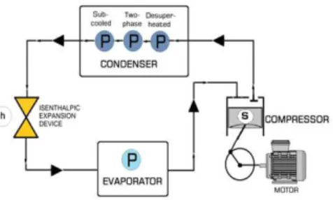
Fig. 1: Analysis on the Condenser.
2.0 Theoretical Considerations: 2.1 Vapor Compression Cycle:
The condenser is a heat exchanger that usually rejects all the heat from the refrigeration system. The condenser accepts hot, high-pressure refrigerant, usually a superheated gas, from the compressor and reject heat from the gas to some cooler substance. As energy is removed from the gas it condenses and this condensate is drained so that it may continue its path back through the expansion valve or capillary to the evaporator The condenser is divided into three regions characterized by the thermodynamic states, such as the de-superheated vapor, the change of phase (two-phase), and the subcooled liquid regions. The refrigerant condenses at a negligible temperature difference from the ambient conditions.
2.2 Dimensionless parameters for fluid flow:
Many dimensionless parameters are generally used in fluid mechanics to characterize the heat transfer and fluid flow behavior. Some important dimensionless parameters associated with heat transfer and fluid flow, which are used in the current study, are briefly described below.
2.2.1 Reynolds number (Re):
Reynolds number (Re) is a very significant parameter in fluid mechanics. It is named after the British engineer and physicist, Osbourne Reynolds. It is defined as the ratio of inertia force to the viscous force and used to characterize the nature and flow regime of fluids. The general expression of Reynolds number is
= =ρ
μ (1)
In this equation:
ρis density of flowing fluid. µis viscosity of the flowing fluid L is a characteristic length of the problem. For pipe flow, L=D where L is the pipe diameter
v is a characteristic velocity of the problem. For pipe flow, v= vm wherevm is the mean velocity
It specifies the flow characteristics, such as laminar, transitional, or turbulent regime. In a flow, usually, the fluid viscous force acts for managing stability of flow, while fluid inertia is liable for disorganizing the flow. For small Reynolds numbers, the inertial force is not that significant, therefore, the flow is laminar and smooth. On the other hand, for high Reynolds number, the inertia plays an important role, and it is dominant. As a result, the flow is turbulent.
2.2.2 Prandtl number (Pr):
The Prandtl number (Pr) is a dimensionless number, which is widely used in heat transfer approximations. It is named after the German physicist Ludwig Prandtl. It is defined as the ratio of momentum diffusivity (kinematic viscosity) to the thermal diffusivity and expressed as
= = μ
(2)
In this equation:
cp is the constant-pressure specific heat of
the flowing fluid.
kis the conductivity of the flowing fluid.
The Pr is related to viscosity, specific heat, and thermal conductivity of the fluid. It describes the development of a thermal boundary layer thickness on the heat transfer surface. The thermal boundary layer is a barrier to the heat transfer. The smaller Pr means that the heat diffuses very quickly than the velocity (momentum).
2.2.3 Nusselt number (Nu):
Nu = *+"#$ ! %!&# #'& ()!' !"#$ ! %!&# #'& ()!'= (3) It depends on channel geometry, fluid heat transfer coefficient, and conductivity. For a circular geometry channel, L = Dch. Therefore, the expression for Nu becomes
Nu =%,-. (4)
where L is the characteristic length, Dchis the channel diameter, h is the heat transfer coefficient, and kis the thermal conductivity of liquid at bulk temperature.
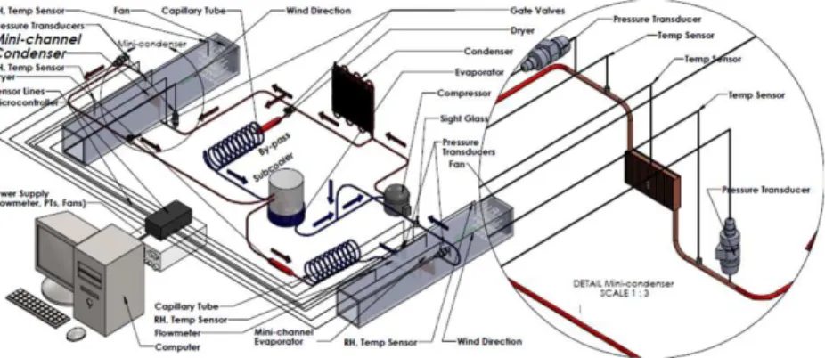
Fig. 2: Experimental Set-up.
2.2Heat Transfer Coefficient:
The Dittus-Boelter (1930) correlation is a common correlation useful for many applications. This correlation is applicable when forced convection is the sole mode of heat transfer. This is an equation quite similar to McAdams (1954) equation at which the application is presented in the literature, which is not restricted to small diameters (Owhaib, 2007). The equation is expressed below as
h = 0.0234Re78.984Pr78.<8=>
?@ (5)
Another correlation developed by Son-Lee (2009) is the single-phase heat transfer coefficient (hL), which is expressed as
h = 0.0344 78.984Pr78.B8=>
?@ (6)
where k is the thermal conductivity of R-134a, D is the hydraulic diameter, Re is the Reynolds number, and Pr is the Prandtl number.
3.0 Description of the Experimental: Work:
Three mini-channel condensers (100 mm x 50 mm x 20 mm copper block) with 1 mm, 2 mm, and 3 mm hydraulic radius for each were fabricated and installed one at a time in the experimental rig as shown in Figure 2. Fins were machined on each face. Each condenser had 24 fins with a width of 2 mm, a length of 50 mm and height of 5 mm. A fan was installed downstream of the heat exchanger to guarantee sufficient air flow across the condenser inside the insulated long duct on the refrigerant-side at the inlet and outlet section in the rig. The condenser set-up was placed in a mini wind tunnel system to simulate the cooling system.
Two temperature sensors and two pressure transducers were installed on the sufficient air flow side across the condenser inside the insulated long duct used in the rig. Two temperature sensors and
two pressure transducers were installed on the refrigerant side at the inlet and outlet of the mini-channel condenser. Another temperature sensor was also installed at the middle of the mini channel condenser. The refrigerant mass flow rate was measured at the outlet of the expansion valve. A valve that passed through the evaporator was used to control the mass flow rate. On the air-side, two temperature sensor spaced equally were installed at the inlet and two at the outlet side. The air velocity over the mini-channel condenser was measured using a hot wire anemometer. Every start of the experiment, the system was vacuumed for about 30-40 min to remove trapped air, followed by leak test before charging the system with the refrigerant R134a. The temperature, flow rate, and pressure readings were automatically recorded, stored and processed by a data acquisition system using LabVIEW software. The data logger was set to scan the data at an interval of 5 minutes.
4.0 Data Analysis and Evaluation of Heat: Exchanger Performance:
The results related to the heat transfer coefficient and pressure drop were obtained from the readings of temperature sensors, pressure transducers, mass flow meter and hotwire anemometer, installed in the test section. The heat rejected in the condenser was calculated using the relation
Q= ms (hin - hout) (7)
wherems is the refrigerant mass flow rate and
obtained directly from the flow meter, hin is the
enthalpy entering the mini channel condenser corresponding to measured pressure and temperature conditions, and hout is the enthalpy leaving the
The average values of experimental heat transfer coefficient were calculated at the average inside surface temperature of the condenser (Suhayla, 2011):
Q = ℎ'E$ 4T(&# − T($7 (8) wherehr is the refrigerant side heat transfer
coefficient, Ai is the inside area of mini channel,
Tsatis the saturation temperature of refrigerant, and
Tsiis the temperature of the inner wall surface.
RESULTS AND DISCUSSIONS
The two parts of the mini-channel condenser (heat exchanger) before they were brazed together through oxy-acetylene are shown in Figure 3. Figure 4 shows the assembled mini channel condenser. Copper is the material of choice for the condenser in this study because of its durability, mechanical strength, and high thermal conductivity. During the brazing process, the surface area of the heat exchanger was carefully observed to avoid clogging
particularly near the entry points of the refrigerant. The variation in the brazing material fill in each channel may also have a marked effect on performance. If some brazing material goes into the channel, it will cause local channel size to become smaller resulting in a reduction in the channel sectional area. This local change in the cross-sectional area may have a drastic effect on the characteristics of the pressure drop. It is worthwhile to note, that this brazed assembly was designed to withstand a pressure of up to 11 bars otherwise exceeding this limitation will damage them. For that reason, these designs were tap after the main condenser. As a result, these mini-channel condensers were only capable of performing the subcooled region out of three different regions namely the de-superheated, saturation and subcooled. It is observed that the resident time of the refrigerant within the heat exchanger decreases which causes a small amount of heat to be absorbed from the surrounding.
Figure 3.Interior part of mini-channel (Unassembled)
Fig. 4: Mini-Channel Condenser.
The theoretical values of the average heat transfer in the refrigerant side of R134a computed from Dittus-Boelter (1930) and Lee-Son (2009) correlations at experimental data were compared with experimental values of heat transfer coefficient from equation 8 as shown in figures 5 to 7. As can be seen in figures 5 to 7, the experimental heat transfer coefficients values ranged from 13 to 98 W/m2-°K for the 1 mm, from 2600 to 9000 W/m2-°K for the 2 mm, and from 3900 to 5200 W/m2-°K for the 3 mm. The heat transfer coefficient is affected by the mass flux and the size of the channel. The heat transfer coefficient is increased with the rise in the mass flux of R134a. Figures 5 to 7 consistently show the calculated heat transfer coefficient values of both
relatively more significant. Many authors have noted this difficulty in attaining the precise measurements on smaller channels that always subject to error. These researchers include Cavallini et al.(2006), Bergles et al. (2010), and Koyama et al. (2003). The difficulties may arise from very small flow rates and amounts of heat, and small dimensions of the test
sections. Another factor to be considered as mentioned by Kandlikar (2006), which is frequently neglected, is the uniformity of the cross-sectional dimensions along the channel flow length. If unaccounted, this error significantly alters the experimental results.
Fig. 5: Variation of heat transfer coefficient with mass flux for condenser size of 1 mm.
Fig. 6: Variation of heat transfer coefficient with mass flux for condenser size of 2 mm.
Fig. 7: Variation of heat transfer coefficient with mass flux for condenser size of 3 mm.
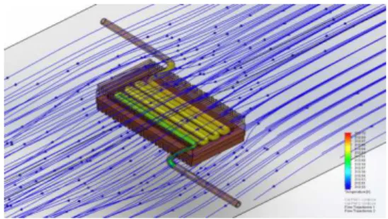
The results of the simulation on the refrigerant temperature of hydraulic diameter D=1mm, D=2mm and D=3mm are shown in Tables 1, 2 and 3 with the corresponding temperature profiles in Figures 8, 9 and 10. The inlet temperatures for hydraulic diameters of D=1mm, D=2mm and D=3mm at the refrigerant side are at 36.38oC, 41.687oC, 37.513oC, respectively. At the air side, the upstream temperaturesat hydraulic diameters of D=1mm, D=2mm and D=3mm, are at 32.398oC, 28.127oC, 32.068oC, respectively. From Figures 8, 9 and 10, one can see that the fluid temperature changes along the mini channel condenser and along the wind tunnel during simulation. These temperature changes help us to clearly understand the heat exchange between two fluids, namely the R-134a and air in the
mini heat exchanger. The simulation results show the temperature profiles along the flow paths of both air and the refrigerant. The colors indicate the increasing temperatures of air as it absorbs heat and the decreasing temperatures of refrigerant as it releases heat.
Table 1: Refrigerant Conditions, Air Conditions and Simulation Results on Temperature from D=1 mm.
Fig. 8: Temperature Profile of the mini-channel for D=1 mm in hydraulic diameter .
Table 2: Refrigerant Conditions, Air Conditions and Simulation Results on Temperature from D=2 mm.
Fig. 9: Temperature Profile of mini channel for D=2 mm in hydraulic diameter .
Table 3: Refrigerant Conditions, Air Conditions and Simulation Results on Temperature from D=3 mm.
Fig. 10: Temperature Profile of mini channel for D = 3 mm in hydraulic diameter.
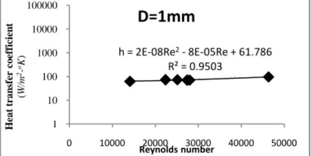
The experimental heat transfer coefficients against Reynolds number are presented in Figures 11, 12 and 13, with the corresponding hydraulic diameters of D=1mm, D=2mm, and D=3mm, respectively. Each curve in the figures displays the
equation of experimental heat transfer coefficient as a function of Reynolds number with the corresponding value of the coefficient of determination. These functions were obtained by the curve fitting or regression with least squares using
Boundary Conditions
Refrigerant Air
Pressure(MPa Temperature(oC) Upstream 32.398 oC
Inlet 1.0383 36.380 Wind Velocity 1.233 m/s
Relative 65.014%
Barometric 100.660 kPa
Simulation Experimental Simulation Experimental
Outlet Downstream
Temperature(oC) 35.24 36.362 32.65 33.03
Boundary Conditions
Refrigerant Air
Pressure(MPa Temperature(oC) Upstream 28.127 oC
Inlet 1.1753 41.687 Wind Velocity 1.233 m/s
Relative 86.541 %
Barometric 100.465 kPa
Simulation Experimental Simulation Experimental
Outlet Downstream
Temperature(oC) 41.43 40.169 30.88 28.775
Boundary Conditions
Refrigerant Air
Pressure(MPa Temperature(o
C) Upstream 32.06781 o C Inlet 1.1109 37.51 Wind Velocity 1.233 m/s
Relative 64.270% Barometric 100.637 kPa
Simulation Experimental Simulation Experimental
Outlet Downstream
Temperature(o
Microsoft Excel. The equations on the graphs could only be used within the range of Reynolds number. There were 6 data points for D=1mm, 5 data points for D=2mm, and 8 data points for D=3 mm, being considered during the fitting of the equation. The
corresponding ranges of Reynolds number were 14000-47000, 110000-350000, and 53000-93000, respectively. It is observed that the experimental heat transfer coefficient increases as the Reynolds number increases.
Fig. 11: Variation of experimental values of heat transfer Coefficient and Reynolds number for D=1 mm.
Fig. 12: Variation of experimental values of heat transfer Coefficient and Reynolds number for D=2 mm.
Fig. 13: Variation of experimental values of heat transfer Coefficient and Reynolds number for D=3 mm.
Fig. 14: Flow of air perpendicular to the fins inside the wind tunnel.
h = 2E-08Re2- 8E-05Re + 61.786
R² = 0.9503
1 10 100 1000 10000 100000
0 10000 20000 30000 40000 50000
H
eat
t
ran
sf
er
c
o
ef
fi
ci
en
t
(W
/m
2 -oK
)
Reynolds number
D=1mm
h = -5E-08Re2+ 0.0476Re - 1980.4
R² = 0.9892
1 10 100 1000 10000 100000
0 100000 200000 300000 400000
H
e
a
t
tr
a
n
sf
e
r
co
e
ff
ic
ie
n
t
(
W
/m
2 -oK
)
Reynolds number
D = 2mm
h = -1E-06Re2+ 0.2138Re - 4086.5
R² = 0.9217
1 10 100 1000 10000 100000
50000 60000 70000 80000 90000 100000
H
e
a
t
tr
a
n
sf
e
r
co
e
ff
ic
ie
n
t
(
W
/m
2 -oK
)
Reynolds Number
Fig. 15: Flow of air parallel to the fins inside the wind tunnel.
Table 4: Average heat transfer coefficient of air on fins orientation.
Figures 14 and 15 show the flow of air perpendicular and parallel to the fins. The values of average heat transfer coefficient for air flow perpendicular to the fins and airflow parallel to the fins with hydraulic diameters of D=1 mm, D=2 mm and D=3 mm are shown in Table 4.
As revealed in Table 4, the average heat transfer coefficient of air consistently exhibits that the air flow perpendicular to the fins is slightly higher than the airflow parallel to the fins. The reason for this difference in the heat transfer coefficient of air could be attributed to the distribution of air on the fins.
6. Conclusions And Recommendations:
Based on the results of this study, the following conclusions are drawn.
1. The fabricated mini channel condensers used in this experiment were only capable of withstanding the pressure of up to 11 bars.
2. The heat transfer coefficient increases with increase in the mass flux in the experimental results and in the calculated values of both Dittus-Boelter and Lee-Son correlations. However, the calculated values of both correlations over-predicted the experimental results. This indicates the inappropriateness of the correlations in small channels.
3. The experimental heat transfer coefficient increases as Reynolds number increases.
4. The simulation results clearly show the temperature profiles along the flow paths of both air and the refrigerant. These temperature profiles are represented in colors to indicate the increasing temperatures of air as it absorbs heat and the decreasing temperatures of refrigerant as it releases heat.
5. The average heat transfer coefficient of air consistently shows that the flow of air perpendicular to the fins is slightly higher than the flow of air parallel to the fins.
The following are recommended for further studies:
1. To conduct more experimental runs using different refrigerant fluids, pressures above 10 bars and hydraulic radii of 1.5 mm, 2.5 mm, and 3.5 mm. 2. To perform similar experiments using condenser made of materials having high thermal conductivity and incorporate this property in the design and fabrication of a cooling system to withstand pressures beyond 11 bars.
3. To analyse a boundary layer for small tubes and channels and utilize the result along with the experimental data in the formulation of a new empirical equation for calculating the heat transfer coefficient.
4. To obtain the thermal distribution and temperature profile inside the mini-channel condensers used in this experiment through a thermal imaging system for better measurement of the local fluid temperatures as well as the surface temperature. 5. To characterize the geometry of the mini-channel used in this experiment in terms of the heat transfer coefficient and the temperature distribution through rigorous investigation of the flow process.
ACKNOWLEDGMENTS
The authors would like to thank the Commission on Higher Education (CHED) and Mindanao University of Science and Technology (MUST) for funding this research.
REFERENCES
Bergles, A.E., 2010. Boiling and Condensation in Small Diameter Channels .Heat Transfer Engineering, 18-40.
Cavallini, A., 2006. Local Heat Transfer Coefficients During Condensation in a 0.8 mm Diameter Pipe . Proceeding International Conference Nanochannels, Microchannels and Minichannels. Limerick, Ireland, 139-146.
(University of California, Berkeley, Publications on Engineering, 2(13): 443
Kandlikar, S.G., 2006. Heat transfer & Fluid flow in Minichannels & Microchannels. 1st Edition UK: Elsevier Science.
Koyama, S., K. Kuwahara, K. Nakashita, K. Yamamoto, 2003. An experimental study on condensation of R134ain a multi-port extruded tube. International Journal of Refrigeration, 26(4): 425-432.
McAdams, W.H., 1954. Heat Transmission (3rd ed. McGraw-Hill Book Company,New York)
Mirza, M.S., 2010. Heat transfer during condensation inside small channels: Applicability of general correlation for macrochannels.Proceedings of
the 14th International Heat Transfer
Conference.Washington, D. C., USA.:125-134. Owhaib, Wahib, 2007. Experimental Heat Transfer, Pressure Drop, and Flow Visualization of R-134a in Vertical Mini/Micro Tubes. Doctoral Theses, KTH, School of Industrial Eng’g. and Management , Energy Technology. Applied Thermodynamics and Refrigeration, 57-58.
Son, C. and H. Lee, 2009. Condensation heat transfer characteristics of R-22, R-134a and R-410A in small diameter tubes( Heat and Mass Transfer, 45:1153–66.
Suhayla, Y.H., 2011. Experimental