TOSHIBA
Telecommunications DivisionSystem Administrator Guide
Release 2
Publication Information
Toshiba Information Systems (UK) Ltd. reserves the right to change any of this information including, but not limited to, product characteristics and operating specifications, without prior notice.
It is intended that the information contained within this manual is correct at the time of going to print, however all liability for errors or omissions is excluded.
© Copyright 2001
Toshiba Information Systems (UK) Ltd. Telecommunications Division
All rights reserved. No part of this manual, covered by the copyrights hereon, may be reproduced in any form or by any means—graphic, electronic, or mechanical, including recording, taping, photocopying, or information retrieval systems—without express written permission of the publisher of this material.
Strata and Stratagy are registered trademarks of Toshiba Information Systems (UK) Ltd.
Contents
Introduction
Equipment Notes ... iv
Organisation ... iv
Conventions ... v
Action/Response Table ... vi
Important Notes ... vi
Related Documents/Media ... vi
Chapter 1
Setting System Parameters
Auto Attendant ... 2
Auto Attendant Exchange Line Assignments ... 2
System Auto Attendant Dialling Plan ... 3
Auto Attendant Announcement Recording Recommendations ... 4
Direct Inward System Access (DISA) Security Code ... 5
Night Transfer ... 6
Night Transfer Lock/Unlock Password ... 6
Night Transfer Lock Mode ... 7
Setting Date/Time/Day ... 8
Soft Keys ... 10
Station Relocation ... 10
Automatic Relocation ... 11
Relocation by Special Dial ... 12
System Messages, Names and Memos ... 13
Contents
System Speed Dial Numbers ... 18
Clearing a Speed Dial Entry ... 18
Accessing the Stored Number ... 18
Speed Dial—Advanced Features ... 19
Feature Access Codes ... 19
Speed Dial Pause and Flash/Recall Storage ... 21
Speed Dial Number Linking ... 22
Speed Dial Memo ... 24
Toll Restriction Override/Travelling Class Codes ... 27
Verified Account Codes ... 29
Appendix B Access Codes
Exchange Line Access Codes ... 31
Feature Access Codes ... 32
Paging Group Codes ... 33
Speed Dial Access Codes ... 34
Appendix C Directories/Record
User Name/Number Directory ... 35
Speed Dial Memo Directory ... 36
Telephone Location Record ... 37
Notes to Users
Introduction
This guide is designed for the System Administrator of the Strata CT system.
This guide provides instructions for assigning the user names that appear on the station display; managing station relocation; and assigning Direct Inward System Access (DISA) security codes, toll restriction override access codes, and verified account codes.
Important! This guide contains information and procedures that are not available to the average telephone user. As System Administrator, you must have access to a specific System Administrator’s telephone to perform the procedures in this guide. You are responsible for certain proprietary codes for providing or restricting features to telephones with the Strata CT systems. This guide is not intended for general use; please keep it in a secure place.
You should also have a copy of the most recent Strata CT General Description for the appropriate system, as well as any related user guides. See “Related Documents/Media” later in this Introduction.
Equipment Notes Introduction
Equipment Notes
♦ Most of the operations in this guide require a Liquid Crystal Display (LCD) digital telephone at the System Administrator’s work station.
♦ Typically, use the station with [PDN] 10, 100, or 200 to perform the functions in this guide. This guide assumes the Adminstrator’s telephone is connected to station Port 000. If you wish, you can use a different [PDN] which must be assigned by the system installer. In any case, the station is referred to as the “Administrator station” throughout this guide. Ask your system installer which station this is.
Organisation
This guide is divided as follows:
♦ Chapter 1 – Setting System Parameters contains descriptions and procedures for changing System Administrator-specific parameters. These parameters are given in alphabetical order. ♦ Appendix A – Access Codes provides feature access code sequences which can be stored onto
SD buttons for one-touch feature access.
♦ Appendix B – Directories/Record provides blank directories for recording User Names/ Numbers and Speed Dial memos, and telephone locations and instructions for displaying [DN], physical port, and logical port information.
Introduction Conventions
Conventions
Conventions Description
Note Elaborates specific items or references other information. Within some tables, general notes apply to the entire table and numbered notes apply to specific items. Important! Calls attention to important instructions or information.
CAUTION! Advises you that hardware, software applications, or data could be damaged if the instructions are not followed closely. WARNING! Alerts you when the given task could cause personal injury or death.
[DN] Represents any Directory Number button, also known as an extension or intercom number. [PDN] Represents any Primary Directory Number button (the extension number for the telephone). An extra appearance of the PDN on the same phone is not considered
as a SDN.
[SDN] Represents any Secondary appearance of a PDN. A PDN which appears on another telephone is considered an SDN. [PhDN] Represents any Phantom Directory Number button (an additional DN).
Arial Bold Represents telephone buttons.
Courier Shows a computer keyboard entry or screen display.
Helvetica Bold Represents LCD displays. “Type” Indicates entry of a string of text.
“Press” Indicates entry of a single key. For example: Type prog then press Enter. Plus (+) Shows a multiple PC keyboard or phone button entry. Entries without spaces between them show a simultaneous entry. Example: Esc+Enter. Entries with
spaces between them show a sequential entry. Example: # + 5. Tilde (~) Means “through.” Example: 200 ~ 220 station range.
➤ Denotes the step in a one-step procedure.
➤ Denotes a procedure.
See Figure 10 Grey words within the printed text denote cross-references. In the electronic version of this document (Strata Technical Library CD-ROM), cross-references appear in blue hypertext.
Action/Response Table Introduction
Action/Response Table
Important Notes
♦ Because feature buttons are flexible and must be programmed by a system installer, your telephone may not have all of the buttons mentioned in this guide.
♦ Use the # button if your telephone does not have a Redial button. ♦ Use the
*
button if your telephone does not have a SpeedDial button.Related Documents/Media
Note Some documents listed here may appear in different versions on the CD-ROM or in print. To find the most current version, check the version/date in the Publication Information on the back of the document’s title page.
Refer to the following documents for more information:
♦ Strata CT General Description provides a system overview including hardware and feature information.
♦ Strata CT Digital Telephone User Guide provides all the procedures necessary to operate Toshiba-proprietary digital telephones, including Single Line Digital Telephone Liquid Crystal Display (LCD) features. It also includes instructions for using the add-on module/DSS console. ♦ Strata CT Digital Telephone Quick Reference Guide provides a quick reference for
frequently-used digital telephone features.
♦ Strata CT Electronic Telephone User Guide explains all the procedures necessary to operate Toshiba-proprietary electronic telephones, including all LCD features. It also includes
instructions for using the electronic DSS console.
➤ The left column gives you the single or numbered steps you need to perform a procedure.
The right column gives the immediate response to your action. It includes readouts from the LCD telephone when applicable, and additional notes and comments.
Introduction Related Documents/Media
♦ Strata CT Electronic Telephone Quick Reference Guide provides a quick reference for frequently-used electronic telephone features.
♦ Strata CT Standard Telephone User Guide explains all the procedures necessary to operate rotary dial and push-button standard telephones.
♦ Strata CT ACD Agent User Guide describes the ACD agent feature operation along with step-by-step procedures for using features.
♦ Strata CT ACD Supervisor Guide provides instruction on how to use the ACD supervisor features.
♦ Strata Library CD-ROM enables you to view, print, navigate and search publications for Strata DK40 and Strata CT digital business telephone systems. It also includes Strata CT ACD
Documentation, including the ACD Agent Guide and ACD Supervisor’s Guide. ACD Installation and Programming instructions are included in the Strata CT Installation and Maintenance Manual and the Strata CT Programming Manual.
Setting System Parameters
1
For security reasons, you can add, delete or change system parameters. Make sure your system is programmed so that you can change these parameters from your telephone.
The parameters discussed in this chapter are given in alphabetical order. They are: ♦ Auto Attendant
♦ Direct Inward System Access (DISA) Security Code ♦ Night Transfer
♦ Setting Date/Time/Day ♦ Soft Keys
♦ Station Relocation
♦ System Messages, Names and Memos ♦ System Speed Dial Numbers
♦ Toll Restriction Override/Travelling Class Codes ♦ Verified Account Codes
Auto Attendant Setting System Parameters
Auto Attendant
The Auto Attendant feature tells the system where to direct incoming Auto Attendant calls. Two announcements greet callers: The primary announcement contains the company greeting, followed by a menu. The secondary (optional) announcement, plays when the station or department called is not available. It is then followed by a menu.
An Auto Attendant's primary announcement may sound like this: “Hello, you have reached Toshiba.
If you know the number of the party you are calling, please dial it now. For operator assistance, dial 0 or please wait.
For Sales, dial 3. For Marketing, dial 4.
And for Technical Support, dial 5.”
Here’s an example of an Auto Attendant's secondary announcement: “The party is unavailable...
For operator assistance, dial 0 or wait for assistance. For Sales, dial 3.
For Marketing, dial 4.
And for Technical Support, dial 5.”
Auto Attendant Exchange Line Assignments
Exchange lines can be assigned to be answered by the Auto Attendant in any of the three system modes (Day, Day 2, and Night) by the system programmer. The Night Transfer button can be used to switch the Exchange lines to ring the Auto Attendant or to ring stations that are preassigned in system programming.
The Auto Attendant can be configured (in system programming) to answer Exchange line calls on a delayed basis (12 or 24 seconds) if the call is not answered at a ringing station(s).
Setting System Parameters Auto Attendant
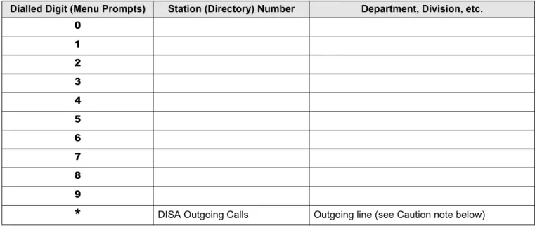
System Auto Attendant Dialling Plan
The Auto Attendant dialling plan is assigned in system programming. Use Table 1 to record your system Auto Attendant dialling plan. Toshiba recommends using single digits. (See Table 2 for a list of default [DNs] for Strata CT systems.)
Table 1 Auto Attendant Menu
Table 2 Default DN’s for Strata CT
When calling the Auto Attendant, callers can access DISA by dialling
*
. Toshiba recommends that you do not include this information in the Auto Attendant announcement.Dialled Digit (Menu Prompts) Station (Directory) Number Department, Division, etc. 0
1 2 3 4 5 6 7 8 9
*
DISA Outgoing Calls Outgoing line (see Caution note below)System [PDNs] (default) [PhDNs] (default)
B1CU 200~255 500~579
B2CAU/B2CBU 200~343 500~739
B3CAU/B3CBU 200~391 500~739
Auto Attendant Setting System Parameters
CAUTION! Make sure that your system DISA security code is set and protected. This is necessary to prevent unauthorised outgoing DISA calls from being charged (billed) to your
company’s telephone lines. See the instructions, “Direct Inward System Access (DISA) Security Code” on Page 5.
Auto Attendant Announcement Recording Recommendations
Primary announcements are played to the caller when the Auto Attendant first answers an Exchange line. Secondary announcements (optional) are played to the caller after dialling a busy or unanswered station. Announcements should be kept as short as possible to allow fast call handling, and to eliminate overflow situations. Typical announcements should run between 10 and 20 seconds. Both primary and secondary announcements should play the Auto Attendant dialling plan options.
If many Exchange lines ring the Auto Attendant (heavy traffic), multiple announcement machines can be installed to accommodate quick answer of incoming calls. The system can support up to four primary announcements and up to four secondary announcements. All primary announcements should play the same message/dial prompts, and all secondary should play the same secondary announcement. Follow the announcement device manufacturer's instructions to record the auto attendant announcements.
Setting System Parameters Direct Inward System Access (DISA) Security Code
Direct Inward System Access (DISA) Security Code
The Direct Inward System Access feature is used when calling into your system from the outside. This feature is available on certain Exchange lines and from the built-in Auto Attendant. Assignments are made by the system programmer. Exchange lines can be DISA lines in the Day, Day 2, or Night mode, or any combination of these modes.
If a caller enters the system via a DISA line or built-in Auto Attendant, the caller can then access another line to place an outgoing call through the system, in which case the outgoing line call is charged as a call made from the CT system. To prevent unauthorised outgoing calls through the system using the DISA feature, enter a DISA security code as shown in the following steps.
CAUTION! Whenever the built-in Auto Attendant is installed, the DISA security code should be used (and changed periodically) to prevent unauthorized access of outgoing Exchange lines via the Auto Attendant DISA access feature.
➤
To enter or change the DISA security code➤
To cancel the DISA security code1. Press [DN] + #658. You hear a confirmation tone.
2. Dial the new DISA security
code (1~15 digits). The DISA security code digit length is a system program option. The code appears on the LCD as you enter it.
3. Press Redial. You hear a confirmation tone.
4. Press Spkr. The telephone returns to the idle mode.
1. Press [DN] + #658. You hear a confirmation tone.
2. Press Redial. The telephone returns to the idle mode. 3. Press Spkr.
NO. NNN ____ ID CODE SET
NO. NNN DATA PROGRAMMED
Night Transfer Setting System Parameters
CAUTION! If the DISA security is cancelled, outgoing unrestricted Exchange Line access is available to anyone calling in on a DISA line or built-in Auto Attendant.
Night Transfer
Incoming calls to your system can be made to route and ring different destinations, based on either two- or three-call routing (ringing) patterns (set in system programming). The Night Transfer LED indicates the active routing pattern:
Night Transfer can be locked by pressing NT Lock (1~4) and dialling the NT Lock password (see the procedure outlined on the following page).
If the system has tenant service, up to four Tenant Night Transfer buttons (Night Transfer 1~4) can be assigned and controlled independently.
➤
To enable/disable night transfer➤ Press Night Transfer to toggle night transfer ON/OFF.
Night Transfer Lock/Unlock Password
The Night (NT) Lock/Unlock mode enables the Administrator’s station or an attendant console to lock the system into the Day, Day 2, or Night mode. By setting the system into different modes, incoming Exchange calls can be routed to different destinations.
In order for the Administrator station or the attendant console to perform such routing, it must be assigned with Night Transfer and NT Lock buttons via system programming. Up to four Night Transfer and NT Lock buttons are allowed. Check with the system installer for any additional information.
Mode Three-pattern Two-pattern
DAY OFF OFF
DAY 2 FLASH N/A
Setting System Parameters Night Transfer
➤
To assign or change Night Lock/Unlock PasswordNight Transfer Lock Mode
After setting the Night Transfer button into the desired ring mode (Day/Day2/Night), you can lock Night Transfer using the accompanying steps below.
➤
To set the system in Night Lock Mode 1. Press a [DN] + #622X(X = Tenant 1~Tenant 4 Exchange line groups), with the handset on-hook.
The LCD prompts you to enter a four-digit password.
2. Enter a four-digit password. As you are enter the password, the digits display on the LCD.
3. Press Redial. You hear confirmation tone.
4. Hang up. The password is assigned.
1. Press Night Transfer to set the system into the Day or Day2 or Night Mode, with the handset on-hook.
2. Press NT Lock. The NT Lock LED flashes. The LCD prompts you to enter your password. 3. Enter your password and press
NT Lock again. Y = Password digits
NO.200 ENTER PASS CODE
NO.200 XXXX
NO.200 DATA PROGRAMMED
NO.200 JAN 15 WED 02:00
NO.200 ENTER PASSWORD
NO.200 YYYY
Setting Date/Time/Day Setting System Parameters
Setting Date/Time/Day
This operation is possible from the Administrator station or attendant consoles and enables you to set the date, time, and day.
➤
To set the dateIf the correct password is entered, the NT Lock LED remains steady red and the LCD displays the message “NT LOCK.”
If an incorrect password is entered, the NT Lock LED turns OFF.
1. Press a [DN] + #651, with the
handset on-hook. You hear a confirmation tone. 2. Enter the date (YYMMDD).
3. Press Redial. You hear a confirmation tone.
4. Press Spkr. The telephone returns to the idle mode.
NT LOCK JAN 15 WED 02:00
#651 ENTER DATE
651 ENTER DATE 001125
NO. NNN MAY 24 MON 12: 05
Setting System Parameters Setting Date/Time/Day
➤
To set the time➤
To set the day of the week1. Press [DN] + #652,with the
handset on-hook. You hear a confirmation tone. 2. Enter the time (HHMMSS) in
the 24-hour clock format. H=hour, M=minute and S=seconds. Use leading zeros: 060530 = 6:05AM and 30 seconds; 143045 = 2:30PM and 45 seconds.
3. Press Redial. You hear a confirmation tone.
4. Press Spkr. The telephone returns to the idle mode.
1. Press a [DN] + #653, with
the handset on-hook. You hear a confirmation tone. 2. Enter the number which
corresponds to the appropriate day of the week:
1 11
1 = Sunday
2 22
2 = Monday
3 33
3 = Tuesday
4 44
4 = Wednesday
5 55
5 = Thursday
6 66
6 = Friday
7 77
7 = Saturday
3. Press Redial. You hear a confirmation tone.
4. Press Spkr. The telephone returns to the idle mode.
#652 ENTER TIME
#652 ENTER TIME 120500
NO. NNN MAY 24 MON 12: 05
#653 ENTER DAY
#653 ENTER DAY 2
NO. NNN MAY 24 MON 12: 05
Soft Keys Setting System Parameters
Soft Keys
➤
To turn Soft Keys on➤ Press Mode + 71.
➤
To turn Soft Keys off➤ Press Mode + 70.
Important! The LCD examples in this guide are shown with Soft Keys turned OFF. If your telephone has Soft Keys turned ON, the displays may be different, but you can still follow the steps in this guide. Generally, the information shown on line 2 displays on line 1 when Soft Keys are ON.
Station Relocation
This feature enables you to relocate an electronic, digital, or standard telephone without requiring reprogramming of the station's features. When relocated, the telephone retains its station number and all programmed features, including personal messages, feature buttons, Toll Restriction Class, and Speed Dial numbers.
One station at a time can be easily relocated. If two stations are unplugged at the same time, the telephone that was unplugged last is relocated when plugged back in. Station Relocation only works with the same type of station. For example, moving electronic telephone to electronic telephone, digital to digital, and standard to standard. The label on the bottom of your telephone indicates “Electronic” or “Digital” key telephone.
If a button telephone is replaced with a 20-button type, the left column of buttons retains the 10-button assignments. With LCD telephones, you use the LCD after relocation, to confirm the desired location of the calling or called [PDNs].
CAUTION! Always turn this feature off promptly after relocation is finished to avoid accidental relocation.
Setting System Parameters Station Relocation
Automatic Relocation
This function enables you to physically move a telephone from one location to another while maintaining all of the telephone's programmed features. Use the “Telephone Location Record” on Page 37 for telephone location tracking.
➤
To turn on the Auto Station Relocation feature➤
To physically relocate (swap) Station A and BImportant! Make sure that the location that the phone is moving to is already vacant.
If you are moving a telephone (for example, Station A) to a new location that already has a telephone connected to it (for example, Station B), disconnect Station B from its telephone jack before you disconnect Station A.
You cannot configure the moving station (Station A) to an already occupied station (Station B).
1. From the Administrator station, press a [DN] + #6282
to turn on the Auto Station Relocation feature.
You hear a confirmation tone indicating the Station
Relocation feature is on. If you hear a busy tone, the Station Relocation feature is already turned on, or you did not dial from the Administrator station.
2. Press Spkr.
1. Verify that the telephone jack for the new location does not have a telephone connected. 2. Unplug the telephone that is
moving from its wall jack at the old location.
3. Plug the telephone that is moving into the wall jack at its new location.
The station is now moved to its new location while retaining its original [DNs] and features.
4. From the Administrator station, press [DN] + #6281
to turn off Auto Station Relocation, then press Spkr.
You hear confirmation tone. If you hear a busy tone, the Station Relocation feature was already turned off, or you did not dial from the Administrator station.
Station Relocation Setting System Parameters
Relocation by Special Dial
This option enables two station numbers and their features to be exchanged with or without physically relocating the telephones. The exchange takes place through the use of special dial codes. For the procedure below, we are using Station A/B and Location 1/2 to demonstrate the exchange.
➤
To turn on the Special Dial Station Relocation feature➤
To relocate (swap) Station A and B 1. From the Administratorstation, press a [DN] + #6283
to turn on the Special Dial Station Relocation feature
2. Press Spkr. You hear confirmation tone indicating that the Station Relocation feature is on. If you hear a busy tone, the Station Relocation feature was already turned on, or you did not dial from the Administrator station.
1. From Station A, press a [DN] + #627NNN (NNN= [DN] of Station B).
You hear confirmation tone. Station A now has the buttons and features of Station B and vice versa.
2. From Administrator station, press a [DN] + #6281 to turn off Special Dial Station Relocation, then press Spkr.
After Station Relocation is turned off, you hear a confirmation tone. If you hear a busy tone, Station Relocation was already turned off, or you did not dial from the Administrator station.
Note After the relocation is completed, exchange the keystrips of the two telephones, if they are different, because a 10-button telephone replaced with a 20-button type telephone, retains the 10-button assignments.
Setting System Parameters System Messages, Names and Memos
System Messages, Names and Memos
You can write or edit station LCD messages, names or numbers.
➤
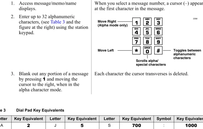
To write LCD messages, names, or numbers 1. Access message/memo/namedisplays. When you select a message number, a cursor (–) appears at the first character in the message. 2. Enter up to 32 alphanumeric
characters, (see Table 3 and the figure at the right) using the station keypad.
3. Blank out any portion of a message by pressing 1 and moving the cursor to the right, when in the alpha character mode.
Each character the cursor transverses is deleted.
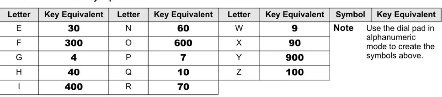
Table 3 Dial Pad Key Equivalents
Letter Key Equivalent Letter Key Equivalent Letter Key Equivalent Symbol Key Equivalent
A 2 J 5 S 700 : 1000
B 20 K 50 T 8 – 10000
C 200 L 500 U 80 + 100000
D 3 M 6 V 800 / 1000000
2358
Toggles between alphanumeric characters Scrolls alpha/
special characters Move Left
Move Right (Alpha mode only)
System Messages, Names and Memos Setting System Parameters
User LCD Name/Number Display
Once you store names and numbers in the system memory for each station or device, they can display on the station’s LCD while idle and at other stations’ LCDs when they are called. The name also appears on the LCD during direct internal, forwarded, and hunted calls. The LCD name does not display on Override or Off-hook Call Announce (OCA) calls.
Name display information for non-LCD telephones or voice mail/auto attendant devices can be stored from the Administrator's digital station. When Name/Number is recorded for non-LCD telephones or other devices, their Name/Number is displayed on LCD telephones when called. The name of a called telephone displays on the calling telephone's LCD when the calling telephone has the Soft Key feature ON.
Note Before entering names for other users, turn the Soft Key feature OFF by pressing Mode Mode Mode Mode + 70
70 70
70 when your telephone is idle. After the names have been entered, turn the feature back on by pressing Mode Mode Mode Mode + 71 71 71 71 when your telephone is idle.
E 30 N 60 W 9 Note Use the dial pad in
alphanumeric mode to create the symbols above.
F 300 O 600 X 90
G 4 P 7 Y 900
H 40 Q 10 Z 100
I 400 R 70
Table 3 Dial Pad Key Equivalents
Setting System Parameters System Messages, Names and Memos
➤
To enter name/number information for your telephone➤
To clear name/number display.1. Press [DN] + #621. Current information displays on the lower line of the LCD.
2. Enter up to 16 alphanumeric characters, (see the figure at the right) using the station keypad.
3. Press Spkr. The information is stored and appears on the top line.
1. Press a [DN] +
#620. You hear confirmation tone, then busy tone. 2. Press Spkr. During the clear, the LCD displays the
message shown on the right.
After the clear, a name is displaced by a message and call forward settings if they are set.
Note This procedure does not erase the name/number. To restore the display, press [DN] + #621.
USER NAME?
TOSHIBA EXT. 200 DATE DAY TIME
NO. NNN USER NAME RESET
NO. 200 DATE DAY TIME
2358
Toggles between alphanumeric characters Scrolls alpha/
special characters Move Left
Move Right (Alpha mode only)
System Messages, Names and Memos Setting System Parameters
➤
To erase name/number display➤
To enter name/number information for other stations/devices1. Press a [DN] + #621. Current information displays on the lower line of the LCD. 2. Press 1 in the alpha mode to
enter blanks. Blank characters replace the information. If all blanks are entered, the telephone [PDN] displays on the LCD. 3. Press Spkr. The information is erased.
1. Turn Soft Keys OFF by pressing
Mode + 70. The Administrator station must be idle. 2. Press a [DN] + #621. Current information for the
Administrator station appears on the bottom line.
3. Press Page. In this particular display, EKT stands for the [PDN] of a digital, electronic or standard telephone.
4. Dial the [PDN] of the station for which the name/number
information is to be recorded.
Current information for station NNN
appears on the bottom line.
5. Press Page. You are prompted for the user name.
USER NAME?
USER NAME?
DESK EKT NO.?
DESK EKT NO. NNN
Setting System Parameters System Messages, Names and Memos
➤
To erase other station name/number displays➤ From the Administrator station, repeat Steps 1~6 of the previous procedure and press 1, in the alpha mode in Step 6.
6. Enter up to 16 alphanumeric characters, (see the figure at the right) using the station keypad.
We suggest that you enter the station number and the user name.
7. Press Spkr. The new information displays on the top line of station NNN’s LCD. The Administrator station LCD returns to the normal idle display.
8. Repeat Steps 2~7 to enter more names/numbers.
9. Press Mode + 71 when your
telephone is idle. Your Soft Keys are turned ON.
2358
Toggles between alphanumeric characters Scrolls alpha/
special characters Move Left
Move Right (Alpha mode only)
System Speed Dial Numbers Setting System Parameters
System Speed Dial Numbers
System Speed Dial telephone numbers can be stored in the system memory by the Administrator station only.
➤
To store a feature or System Speed number in a System Speed Dial CodeClearing a Speed Dial Entry
➤ Repeat the preceding procedure, skipping Step 4.
Accessing the Stored Number
Note Write down the Speed Dial codes and telephone numbers for future reference. 1. Press Redial, with the headset on-hook.
2. Press SD button
...or Speed Dial + System Speed Dial
Code. See Table 8 on page 34.
3. Input the telephone number to be stored (up to 20 digits).
...or enter the feature code sequence. See Table 4 on page 20.
4. Press Redial. The information is stored in memory. 5. Repeat Steps 1~5 for each telephone
number to be stored.
➤ Press Speed Dial + its associated Speed Dial access code
...or press the SD button associated with the code.
Setting System Parameters Speed Dial—Advanced Features
Speed Dial—Advanced Features
Feature Access Codes
You can program SD (Speed Dial) buttons with feature access codes for a single feature or a sequence of features as long as the keyed dial pad characters do not exceed 20 digits. To determine how many digits you have, count 2 digits for Cnf/Trn, [PDN] and Hold feature buttons and 1 digit for all other dial pad characters.
See Table 4 for a list of feature access codes.
➤
To store a feature onto a SD button➤ Redial + SD + Feature Access Code + Redial.
♦ See Table 4 on the following page for Feature Access code sequences. ♦ SD = the speed dial button the feature is stored on.
➤
To store a feature onto a speed dial code➤ Redial + Speed Dial + Speed Dial Access Code + Feature Access Code + Redial.
Important!
● Do not lift the handset.
● If you do not enter the entire sequence within a specified time (set in system programming for
either one or three minutes), the operation times out and your telephone returns to idle mode.
● If your telephone does not have a Speed Dial, press “*” instead of Speed Dial and enter 44
instead of # in all feature sequences.
Speed Dial—Advanced Features Setting System Parameters
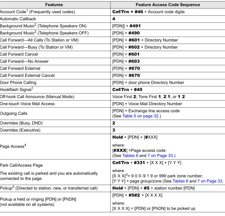
Table 4 Feature Access Codes
Features Feature Access Code Sequence
Account Code1 (Frequently used codes) Cnf/Trn + #46 + Account code digits
Automatic Callback 4
Background Music2 (Telephone Speakers ON) [PDN]] + #491 Background Music2 (Telephone Speakers OFF) [PDN] + #490
Call Forward—All Calls (To Station or VM) [PDN] + #601 + Directory Number Call Forward—Busy (To Station or VM) [PDN] + #602 + Directory Number
Call Forward Cancel [PDN] + #601
Call Forward—No Answer [PDN] + #603
Call Forward External [PDN] + #670
Call Forward External Cancel [PDN] + #670
Door Phone Calling [PDN] + door phone Directory Number
Hookflash Signal1 Cnf/Trn + #45
Off-hook Call Announce (Manual Mode) Voice First 2; Tone First 1, 21, or 12 One-touch Voice Mail Access [PDN] + Voice Mail Directory Number Outgoing Calls [PDN] + Exchange line access code(See Table 5 on page 32.)
Overrides (Busy, DND) 2
Overrides (Executive) 3
Page Access4
Hold + [PDN] + [#XXX] where:
[#XXX] =Page access code (See Tables 6 and 7 on Page 33.) Park Call/Access Page
The existing call is parked and you are automatically connected to the page.
Cnf/Trn + #331 + [X X X] + [Y Y Y] where:
[X X X]3= 9 0 0~9 1 9 or 999 park zone number;
[Y Y Y] = page group/zone (See Tables 6 and 7 on Page 33. Pickup4 (Directed to station, new, or transferred call) Hold + [PDN] + #5 + station number [PDN]
Pickup a held or ringing [PDN] or [PhDN] (not available on all systems)
[PDN] + #5#2 + [X X X X] where:
Setting System Parameters Speed Dial—Advanced Features
Speed Dial Pause and Flash/Recall Storage
Some Speed Dial numbers may require a pause (long or regular) or hookflash be included (e.g., tone delay requires a pause at the beginning of a Speed Dial number).
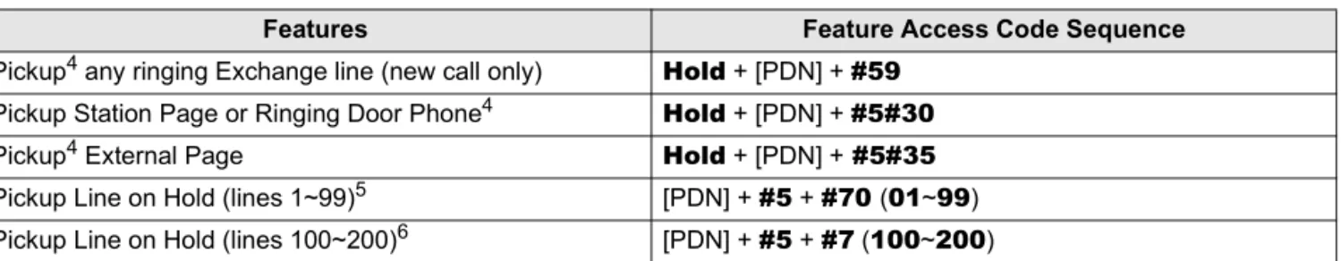
Pickup4 any ringing Exchange line (new call only) Hold + [PDN] + #59 Pickup Station Page or Ringing Door Phone4 Hold + [PDN] + #5#30
Pickup4 External Page Hold + [PDN] + #5#35
Pickup Line on Hold (lines 1~99)5 [PDN] + #5 + #70 (01~99) Pickup Line on Hold (lines 100~200)6 [PDN] + #5 + #7 (100~200)
1. These codes can be used during an Exchange line call.
2. Background music speakers can only be turned ON/OFF from the Administrator’s telephone.
3. XXX = Auto Park Orbit 9 9 9 (access the next available park orbit), or General Park Zones 900~919, or [PDN] on which the call should be parked. Only use 999 with LCD telephones.
4. This feature will hold an existing call when the button is pressed. If the button is pressed when not on a call, pickup or page will still be accessed. These codes can be used during an Exchange line call.
5. After pressing the feature button, the user dials the line number (01~99) to pickup the line. 6. After pressing the feature number, the user dials the line number (100~200) to pickup the line.
Hookflash Regular Pause Long Pause
The Flash button stores a flash signal only if Spd Dial Pause is programmed as a flexible button on the telephone. The flash signal is 0.5 or 2 seconds long (set in system programming) and is displayed on the LCD as “F-”.
Press Flash
...or enter the hookflash dial code (Cnf/ Trn + #45).
The pause is either 1.5 or 3 seconds (set in system programming). The LCD displays “P-”.
Press Spd Dial Pause
...or if Spd Dial Pause is not on the telephone, press Flash to store a pause.
Ten-second pause, which can be entered anywhere in the Speed Dial number. The LCD displays “L-”. Press Spd Dial Lng Pause. Table 4 Feature Access Codes (continued)
Speed Dial—Advanced Features Setting System Parameters
Speed Dial Number Linking
You can link any of the Station Speed Dial numbers to System Speed Dial codes or to any of the optional buttons associated with these codes. The Administrator station can be used to link System Speed Dial Codes. This enables lengthy digit strings to be stored under one Station Speed Dial button or code.
The number directly stored in the System Speed Dial number dials out first, then the number linked to it. Typically, a company’s special carrier access telephone numbers are stored as part of the digit string.
➤
To link system/system speed dial numbers 1. Press Redial.2. Press SD
...or Speed Dial + a System Speed Dial Access Code.
See Table 8 on page 34 for Station Speed Dial Access Codes.
3. Press Speed Dial.
4. Enter the System Speed Dial Access Code to which the number will be linked.
See Table 9 on page 34 for System Speed Dial Access Codes.
5. Enter the telephone number to be stored (max. 17 digits).
6. Press Redial. The number is stored and is automatically dialed when the optional linked station SD button is pressed or the linked Station Speed Dial access code is dialed.
Setting System Parameters Speed Dial—Advanced Features
Linked Speed Dial Example
Note Your system must be programmed for “Toll Restriction Override by System Speed Dial” to allow this example.
➤
To store an Exchange line access code plus a long distance carrier access code (10288) and link to *690In the following example, you are going to link
*
990 to a telephone number and store it in System Speed Dial location*
600.1. Press Redial + Speed Dial + 990 + [PDN] +
910288 + Redial
The Exchange line access code and the long distance carrier code (910288) in the System Speed Dial location
*
990 is stored.Note “I” displays when the [PDN] is stored.
♦ [PDN] is used to automatically access internal dial tone before dialling 910288.
♦ 910288 = 9 is the Exchange line access code and
10288 is the long distance carrier access code. 2. Store the System Speed Dial
information on Speed Dial Code 600 from the Administrator station. 3. Press Redial +Speed
Dial+ 600+Speed Dial
+ 99017145553700 +
Redial.
♦ 600 is the System Speed Dial Code.
♦ 990 is the System Speed Dial Code that is being linked to code 600.
♦ 17145553700 is the telephone number with area code.
Speed Dial—Advanced Features Setting System Parameters
➤
To use the new link➤ From any station, press Speed Dial +
*
600 or press SD (600) button if available on the calling station. The telephone automatically dials 9 to access an Exchange line, then the carrier access code (10288) plus the telephone number (17145553700).Speed Dial Memo
This feature enables the Administrator station to program an 11- or 12-character name for each of the system Speed Dial numbers. You can scroll through the memo pad of names to select the appropriate party.
Notes
● Before entering names for Speed Dial Numbers, turn off the Soft Key feature by pressing Mode + 70 when the telephone is idle. After entering the names, turn the feature back on by pressing the Mode + 71 when the telephone is idle.
● For your convenience, use the “Telephone Location Record” on Page 37 for recording speed dial numbers with memos from the Administrator station.
➤
To program names and numbers1. Press Redial, then Speed Dial. The LCD displays:
2. Enter the Speed Dial number. The current name/memo and its code displays (see Tables 8). 3. Press Mode. The name/memo appears as you enter it.
Setting System Parameters Speed Dial—Advanced Features
4. Enter up to 12 alphanumeric characters, (see the figure at the right) using the station keypad.
5. Press Mode.
6. Press [PDN], then enter the desired Exchange line access code, plus the telephone number (20 digits maximum).
The number appears as you entered it. Speed Dial numbers and memos and their corresponding two- or three-digit codes can be recorded on the Speed Dial Memo Directory at the back of this guide.
Note If telephones use direct appearing Exchange line buttons to place outgoing calls–do not press [PDN] in Step 6.
7. Press Redial. The data is recorded into memory. 8. Repeat Steps 1~7 to enter more
names/memos.
2358
Toggles between alphanumeric characters Scrolls alpha/
special characters Move Left
Move Right (Alpha mode only)
Speed Dial—Advanced Features Setting System Parameters
➤
To view and/or dial a Speed Dial number➤
To check a Speed Dial number1. Press Mode + 8XXX. The Speed Dial number appears with a name or memo.
XXX = Personal or System Speed Dial Codes. See Tables 8.
Note It is recommended that you record Speed Dial numbers and memos and their corresponding three-digit codes on the Speed Dial Memo Directory at the back of this guide.
2. Press Page to scan the directory for the appropriate number/memo.
3. Press any available Line or [DN] + an Exchange Line Access Code.
The number is dialled.
See “Exchange Line Access Codes” on Page 31.
1. Press Mode + 8. See Tables 8. The LCD displays a “+” sign if there are more than 16 digits.
2. Enter a speed dial code. Note If the number is longer than 16 digits, press Scroll to display the remaining digits.
3. To see the next number, press
Page.
Setting System Parameters Toll Restriction Override/Travelling Class Codes
Toll Restriction Override/Travelling Class Codes
As a System Administrator, you can add or change Toll Restriction Override codes. When a station dials these override codes, after accessing an outside line or LCR, the station Toll Restriction Class is changed to that assigned to the override code dialled (Travelling Class). To add, change or delete Toll Restriction Override or a Travelling Class code, the following steps must be performed from the Administrator’s telephone.
➤
To add/delete/change toll restriction override or travelling class codes 1. Press [DN]. You hear a confirmation tone. 2. Enter the Travelling Class accesscode #691~#698 The code appears on the LCD as you enter it and you hear a dial tone.
...or enter #691~#698 to change the assigned TR Class 01~08 Travel Class Codes respectively. ...or enter the Toll Restriction
Override access code #654~#655 #654~#655 represent override Codes 1 and 2 respectively.
3. Enter the desired four-digit override code.
NO.NNN ENTER OVR. CODE
Toll Restriction Override/Travelling Class Codes Setting System Parameters
➤
To delete toll restriction override or travelling class codeVerified Account Codes 4. Press Redial. You hear a confirmation tone.The code is stored in memory.
Notes
● When making outgoing calls, dialling the Travelling Class code puts the telephone in the Toll Restriction class of the code that was dialled.
● When making outgoing calls, dialling the Override code, overrides all toll restrictions that may be normally applied to the telephone.
● The Toll Restriction Travel Class/Override codes do not print on SMDR reports.
5. Repeat Steps 1~3 to enter up to eight Travelling Class codes and two Toll Restriction Override codes.
6. Press Spkr. The telephone returns to the idle mode.
1. Press a [DN] and dial the assigned toll restriction override change access code:
#691~#698 or #654~#655.
You hear a confirmation tone.
2. Press Redial. You hear confirmation tone.
3. Press Spkr. The telephone returns to the idle mode.
NO. NNN DATA PROGRAMMED
Setting System Parameters Verified Account Codes
Verified Account Codes
Adding, deleting, or changing Verified Account Codes can be done at designated stations only. The privileged stations are assigned by the system programmer.
➤
To add or change verified account codes1. Press [DN] + #659. You hear a confirmation tone.
2. Enter the desired three-digit verified account code reference number (000~299) or
(000~499) for some systems.
Account codes appear on the LCD as you enter them. All systems have 300 account code numbers (000~299), except the B5CAU/B5CBU processor, which has 500 (000~499).
3. Enter the verified account code. The system is programmed for ___digits.
Account codes can be 4~15 digits long; the number of digits is set system wide for all account codes in system programming. The code appears on the LCD as you enter it.
4. Press Redial. You hear a confirmation tone. The code is stored.
5. Press Spkr.
6. Repeat Steps 1~4 to enter more
verified account codes. The telephone returns to the idle mode.
NO.NNN VERIFY ACC SET
NO.NNN ERIFY ACC SET XXX
NO.NNN XXX XXXXXXXXXXXXX
NO.NNN DATA PROGRAMMED
Verified Account Codes Setting System Parameters
➤
To delete verified account codes1. Press [DN] + #659. You hear a confirmation tone. 2. Enter the three-digit verified account
code reference number (000~299) or (000~499) to be deleted.
You hear a confirmation tone.
3. Press Redial. The telephone returns to the idle mode. 4. Press Spkr.
Access Codes
A
This appendix contains access codes for outside Speed Dial numbers, Exchange lines, Paging Group and Paging Zone Codes.
Exchange Line Access Codes
Exchange lines are used when you dial an outside number. If your telephone does not have a CO or
Line button, you can enter the appropriate code listed in Table 5 to access an outside line.
You can also store the code on a Speed Dial (SD) button for one-touch access. If you are storing an Exchange line access code onto a Speed Dial code, enter 44 before the Exchange access code (e.g., to store code #7001, enter 447001).
In some systems, 9 is used as a general group code or to access Least Cost Routing (LCR). System users are required to dial 9 in order to access an outside line. If you press 9 in a system programmed with LCR, you may not hear internal dial tone, depending on system programming.
Feature Access Codes Setting System Parameters
➤
To access a line➤ Press [PDN] + Exchange Line Access Code (Table 5).
Notes
● 9 accesses LCR or general line group.
● 801~816 accesses line groups 1~16, respectively.
● #7001~#7200 accesses individual lines 1~200, respectively.
Feature Access Codes
See Table 4 on page 20.
Table 5 Exchange Line Access Codes
Processor Exchange Line Access Codes
B1CU 9 or 801~808 or #7001~#7032 B2CAU/B2CBU & B3CAU/B3CBU 9 or 801~816 or #7001~#7120
Setting System Parameters Paging Group Codes
Paging Group Codes
Your telephone can be assigned to page group(s). Telephones can be a member of more than one group and each group can have as many as 120 stations. Station users can access each group separately by dialling an access code (see Table 6 and Table 7 on page 33 ).
➤
To enter a paging group access code➤ Press [PDN] + Access Code Table 6 Paging Groups
Paging Group Access Code Paging Group Access Code
Station Group A #311 Station Group E #315
Station Group B #312 Station Group F #316
Station Group C #313 Station Group G #317
Station Group D #314 Station Group H #318
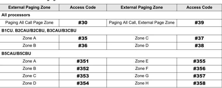
Table 7 External Paging Zones
External Paging Zone Access Code External Paging Zone Access Code All processors
Paging All Call Page Zone #30 Paging All Call, External Page Zone #39 B1CU. B2CAU/B2CBU, B3CAU/B3CBU
Zone A #35 Zone C #37
Zone B #36 Zone D #38
B5CAU/B5CBU
Zone A #351 Zone E #355
Zone B #352 Zone F #356
Zone C #353 Zone G #357
Speed Dial Access Codes Setting System Parameters
Speed Dial Access Codes
The number of station and system speed dial numbers available to you depends on the size of your company’s telephone system. Check with your System Administrator to find out which codes apply to your system.
Once you store a telephone number on any of the codes listed below, you can dial the number by entering the code, such as
*
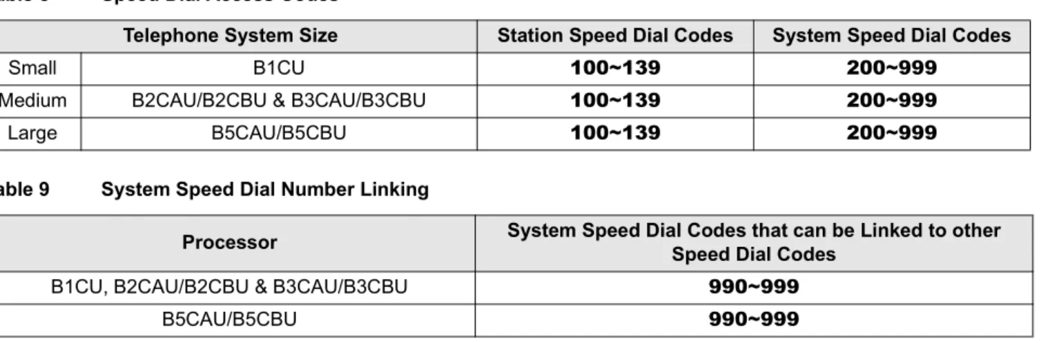
100 or Speed Dial + 100.Table 8 Speed Dial Access Codes
Telephone System Size Station Speed Dial Codes System Speed Dial Codes
Small B1CU 100~139 200~999
Medium B2CAU/B2CBU & B3CAU/B3CBU 100~139 200~999
Large B5CAU/B5CBU 100~139 200~999
Table 9 System Speed Dial Number Linking
Processor System Speed Dial Codes that can be Linked to other Speed Dial Codes
B1CU, B2CAU/B2CBU & B3CAU/B3CBU 990~999
Directories/Record
B
User Name/Number Directory
Name/Numbers are limited to 16 alphanumeric characters and are displayed on the top row or idle LCD stations and the bottom row of called LCD stations.
This directory is provided for the Administrator station for referencing and recording of other station Name/Numbers.
Station #:__________
Station #:__________
Station #:__________
D
A
T
E
D
A
Y
T
I
M
E
D
A
T
E
D
A
Y
T
I
M
E
Speed Dial Memo Directory Setting System Parameters
Station #:__________
Speed Dial Memo Directory
Speed Dial memos are limited to 12 characters for the memo (top row of LCD) and 16 digits/pauses for the dial number (bottom row of LCD).
This directory is provided for recording Speed Dial numbers with memos from the Administrator station.
*
Code: 11-Character Memo ExampleD
A
T
E
D
A
Y
T
I
M
E
*
6
0
0
-
M
E
M
O
H
E
R
E
S
P
E
E
D
D
I
A
L
#
H
E
R
E
*
-*
-*
-Setting System Parameters Telephone Location Record
Telephone Location Record
➤
To view [PDNs], port numbers (physical and logical), and [DNs] of LCD telephonesNote It is recommended that each location, [PDN], and user name are recorded in the table provided below.
1. Press a [DN] + #401. The [PDN] is displayed as INT = NNN (NNN = directory number of button).
2. Press a [DN] + #402. The “Physical” port number and the “Logical” port number of an LCD telephone is displayed.
3. Press any [DN] + #407 to display
the button directory number. The button [DN] is displayed as DN = NNN(NNN = directory number of button).
Telephone Location Record Setting System Parameters
Notes to Users
Step 1: Safety Approval
Toshiba Information System (U.K.) Ltd declare that the Strata CT complies with the EEC’s LVD directive, (Directive No. 73/23/EEC). The product has been assessed and found to comply with EN60950:2000.
The notes listed below form part of the products compliance with the aforementioned European Norm.
1-1. The system, PCOU/RCOU/RCOS unit, must be earthed. The earth connection must be hardwired to a main distribution point. The main cabinet must be earthed.
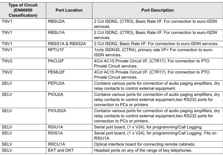
1-2. Table A1 below identifies and classifies the ports available on the system: Table A1
Type of Circuit (EN60950 Classification)
Port Location Port Description
SELV Power Supply
BPSU672F
For connection of external 24 volt batteries.
SELV Processor Boards:
B1CU1F, B2CAU1A, B3CAU1A, B5CAU1A
For connection of external Music-on-Hold source
SELV PDKU2A For connection of Toshiba propriety terminals.
SELV PEKU2F For connection of Toshiba Visually Handicapped Console terminals.
TNV3 RSTU1F For connection of approved 2 wire devices.
TNV3 RSTU3F For connection of approved 2 wire devices.
TNV3 PCOU2F/PCOUS2F For connection to PTO provided Loop Call Unguarded Clear exchange lines.
Safety Approval Notes to Users
Any peripheral apparatus connected to the above ports must have the same EN60950 classification. ie.
♦ SELV ports must only be connected to SELV type ports. ♦ TNV ports must only be connected to TNV type ports.
1-3. The system must hardwired into a switched fused spur, this spur must be installed in accordance with 16th edition of the IEE wiring regulations, aka BS7671:1992. 1-4. Environmental Installation details.
TNV1 RBSU2A 2 Cct ISDN2, (CTR3), Basic Rate I/F. For connection to euro-ISDN services.
TNV1 RBSU1A 2 Cct ISDN2, (CTR3), Basic Rate I/F. For connection to euro-ISDN services.
TNV1 RBSS1A & RBSS2A 2 Cct ISDN2, Basic Rate I/F. For connection to euro-ISDN services. TNV1 RPTU1F 1ccts ISDN30, (CTR4), primary rate I/F> For connection to
euro-ISDN services.
TNV2 PACU2F 4Cct AC15 Private Circuit I/F, (CTR17). For connection to PTO Private Circuit services.
TNV2 PEMU2F 4Cct AC15 Private Circuit I/F, (CTR17). For connection to PTO Private Circuit services.
SELV PEPU2A Contains various ports for connection of audio paging amplifiers, dry relay contacts to control external equipment.
SELV PIOU2A Contains various ports for connection of audio paging amplifiers, dry relay contacts to control external equipment,two RS232 ports for connection to PCs or printers.
SELV PIOUS2A Contains various ports for connection of audio paging amplifiers, dry relay contacts to control external equipment,two RS232 ports for connection to PCs or printers.
SELV RSIU1A Serial port board, (1 x V24), for programming/Call Logging. SELV RSIS1A Serial port board, (1 x V24), for programming/Call Logging. Fits on
RSIU1A.
SELV RRCU1A Optical interface board for connecting remote cabinets. SELV EKT and DKT Headset ports on any of the range of key telephones. Table A1 (continued)
Type of Circuit (EN60950 Classification)
Notes to Users EMC Compliance
The Strata CT is designed to work within the following environmental conditions:
♦ Operating temperature 0oC to 40oC ♦ Humidity 20% to 80%
1-5. Lithium Batteries
Warning! All service personnel are informed that Lithium type battery cells are fitted to the
following units - B1CU1F, B2CAU1A, B2CBU1F, B3CAU1A, B3CB1F, B5CAU1A, B5CBU1F. In accordance with safety requirements you are advised that in the event of these cells going faulty, the entire unit must be returned to Toshiba Information Systems for correct disposal. Under no circumstances must the cells be removed or replaced.
Step 2: EMC Compliance
Toshiba Information Systems (U.K.) Ltd declare that the Strata CT complies with the EEC’s EMC directive, Directive No. 89/366/EEC as amended by directive 92/31/EEC. The product has been assessed and found to comply with the following generic standards, in the present absence of any product specific standards:
♦ EN55022:1998, (Emissions) ♦ EN52024:1998 (Immunity)
The notes listed below form part of the products’ compliance with the aforementioned European Norm.
To ensure EMC compliance the system must installed in accordance with the instructions in the “Installation and Maintenance” manual. In order to maintain compliance any shielded cables supplied and/or ferrite suppression cores must be used.
Equipment details
Base Cabinet Dimensions: Expansion Cabinet Dimensions: Height - 296mm
Width - 672mm Depth - 270mm
Weight - 14.1kg (fully equipped)
Height - 254mm Width - 672mm Depth - 270mm
Type Approval Notes to Users
Step 3: Type Approval
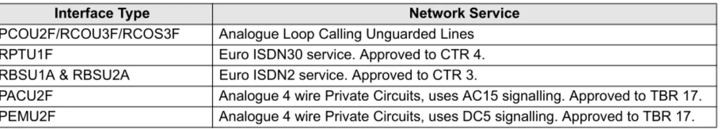
Toshiba Information Systems (UK), Ltd, (TIU), hereby declares that the Strata CT product complies with the requirements of the EC Directive 1999/5/EC, (aka Radio & Telecommunications Terminal Equipment directive). A manufacture’s Declaration under this Directive allows connection to the relevant Public Network Services and the right to place the Product on the market.
The Strata CT is classified as “Call Routing Apparatus” it is intended to be connected to the various Public Telecommunications Network Services for the purpose of generating and terminating “calls”. Table A2 below lists the intended purposes of all the system interfaces.
The system must be installed in accordance with BS6701 parts 1 and 2, the latest issue shall apply. Toshiba Information Systems claim approval to OFTEL general variation NS/V/1235/P/100020. The information contained in this paragraph supports Toshiba’s claim:
The following features require the interconnection of 2 or more exchange lines.
♦ Multi-party conferencing ♦ Call Forward External*
♦ Translation of Un-used Extension numbers* ♦ DISA*
*Warning! These features can allow an Incoming callers access to an outgoing exchange line. There is an engineering programming parameter which can disable these features. In addition the DISA feature can be “password” protected. USERS SHOULD BE AWARE THAT THESE FEATURES CAN BE USED FOR FRAUDULENT PURPOSES. Please consult your supplier to ensure any necessary security measures are enabled.
Table A2
Interface Type Network Service
PCOU2F/RCOU3F/RCOS3F Analogue Loop Calling Unguarded Lines
RPTU1F Euro ISDN30 service. Approved to CTR 4.
RBSU1A & RBSU2A Euro ISDN2 service. Approved to CTR 3.
PACU2F Analogue 4 wire Private Circuits, uses AC15 signalling. Approved to TBR 17. PEMU2F Analogue 4 wire Private Circuits, uses DC5 signalling. Approved to TBR 17.
Notes to Users Network Planning Information
Step 4: Network Planning Information
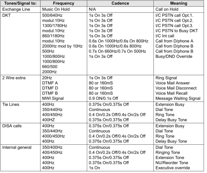
4-1. Strata CT Tone Plan.
Table A3 below lists the characteristics of the tones and signals used in Strata CT.
Tones/Signal to: Frequency Cadence Meaning
Exchange Line Music On Hold N/A Call on Hold
DKT 500/640Hz modul.10Hz 1300/1780Hz modul.10Hz 860/1180Hz modul.10Hz
2000Hz mod by 10Hz 500Hz
1000/800Hz 1000/800Hz 660/500 2000Hz
1s On 3s Off 1s On 3s Off 1s On 3s Off 1s On 3s Off 1s On 3s Off
0.6s On 1000Hz/0.6s On 800Hz 0.6s On 1000Hz/0.6s 800Hz 0.7s On 660Hz/0.7s On 500Hz 1s On 3s Off
I/C PSTN call Opt.1. I/C PSTN call Opt.2. I/C PSTN call Opt.3. I/C PSTN to Busy DKT I/C Int call
Call from D/phone A Call from D/phone B Call from D/phone B Busy/DND Override
2 Wire extns 20Hz DTMF A DTMF D DTMF B MWI Signal
1s On 3s Off 80 or 160mS 80 or 160mS 80 or 160mS 0.9 ON/0.1s Off
Ring Signal Voice Mail Answer Voice Mail Disconnect Voice Mail Recall Message Waiting Signal
Tie Lines 400Hz
350/440Hz 400/450Hz 400HZ
0.375s On/0.375s Off Continuous
0.4 On/0.2s Off/0.4s On/2s Off 0.375s On/0.375s Off
Extension Busy Dial Tone Ring Tone Delay Busy Tone
DISA calls 400Hz
350/440Hz 4000/450Hz 400Hz
0.375s On/0.375s Off Continuous
0.4 On/0.2s Off/0.4s On/2s Off 0.375s On/0.375s Off
Extension Busy Dial Tone Ring Tone Delay Busy Tone Internal general 350/400Hz
400/450Hz 400Hz 400Hz 400Hz
Continuous
0.4 On/0.2s Off/0.4s On/2s Off 0.375s On/0.375s Off
0.375s On/0.375s Off 1s On Dial Tone Ringing Tone Extension Tone NU/Reorder Tone Executive override
Network Planning Information Notes to Users
4-2. System Port to Port losses.
Table A4 below lists the various “typical” transmission gains/losses when inter-connecting the various port types.
-Values indicate a transmission loss. 4-3. Loudness Rating.
The table below lists the measured loudness rating of the Toshiba proprietary terminals. SLR and RLR @ 0km PSTN. (All values are +/-dB)
Sys Port Type PCOU2F RBSU1A RPTU1F PEMU2F PACU2F RSTU3F
to fm to fm to fm to fm to fm to fm
PCOU2F/RCOU3F/RCOS3F 3.7 3.7 1.8 1.9 1.8 1.9 3.1 3.2 -0.7 -1.5
RPTU1F 1.9 1.8 0 0 0 0
RBSU2A 1.9 1.8 0 0 0 0
PEMU2F 3.1 3.2 1.3 1.3 1.3 1.3 2.6 2.6 -2.0 -2.0
PACU2F -0.7 -1.5 -3.4 -2.5 -3.4 -2.5 -2.0 -2.0 -6.0 -6.0
RSTU3F _0.5 -1.0 -2.4 -2.8 -2.4 -2.8 -1.1 -1.5 -5.9 -6.2 -5.2 -5.2
System Port Type PDKU2F ITS-A
SLR RLR
PCOU2F/RCOU3F/RCOS3F 1dB -5dB to -16dB
RPTU1F/RBSU1A/TBSU1A 6dB 2dB to -10dB
PEMU2F 4dB -2dB to -14dB
Index
A
about this book conventions v important notes vi organisation iv related documents vi access codes
exchange line 31 feature 19 speed dial 34 access DISA 3 account codes
revision 27 verified 28, 29 auto attendant 1, 4
announcement recording recommendations 4 dialling plan 3
exchange line assignments 2 menu 3
system dialling plan 3 automatic station relocation
physically 11
swap buttons/features 11
C
codes
feature access 19 paging group 33 speed dial access 34 toll restriction override 27 travelling class 27
verified account 28, 29
D
day 2 mode 6 day mode 6
day/day 2/night modes 2, 5, 6 default DNs 3
dial pad key equivalents 13 directories 35
speed dial memo 36 user name/number 35 DISA
access 3
outgoing calls 3 security code 1, 4, 5
cancel 5 enter/change 5
Index
E
equipment notes iv exchange lines 4
access codes 31
auto attendant assignments 2
F
feature access codes 19 flash button 21
L
LCD name/number information clear 15
enter 15 erase 16
other stations/devices enter name/number 16 erase name/number 17 linked speed dial example 23
M
memos 13 messages 13
multiple announcement machine 4
N
names 13 night mode 6 night transfer 1, 2, 6
enable/disable 6 lock mode 7
lock/unlock password 6 assign/change 7 routing (ringing) patterns 6
non-LCD telephones 14
P
page button 16, 26 paging group codes 33 primary announcement 2, 4
R
records 35
telephone location 37 relocation by special dial 12
S
secondary announcement 2, 4 setting date/time/day 1, 8, 9 soft keys 1, 10, 16, 24
to turn off 10 to turn on 10 speed dial 18, 24
access codes 34
accessing stored number 18 advanced features 19 checking a number 26 clearing an entry 18 dialling 26
flash 21 long pause 21 memo 24
program names and numbers 24 number linking 22
example 23
store exchange line access code 23 use new link 24
Index
storing a feature 18
storing system speed dial number in a system speed dial code 18
system numbers 18 view 26
station (directory) number 3 station relocation 1, 10
automatically relocate 11 relocation by special dial 12 system
auto attendant dialling plan 3 messages, names and memos 1, 13 setting parameters 1
speed dial memo numbers 1 speed dial numbers 18
T
telephone location record 24 tenant service 6
toll restriction override 1, 27 add/delete/change 27 by system speed dial 23 delete 28
travelling class codes 1, 27 add/delete/change 27 delete 28
U
user LCD name/number display 14 clear 15
erase 16
other stations/devices
enter name/number display 16 erase name/number display 17 write 13
V
verified account codes 1, 28, 29 add/change 29
delete 30
W
write
LCD memos 13 LCD messages 13