White Paper
Scalable Session Border Control Capabilities
for Service Provider Networks
Voice over IP (VoIP), video streaming, instant messaging, and gaming are just a few of the real-time, IP-based applications enjoying rapid growth in today’s competitive communications market. Service providers are now finding it efficient and economical to directly interconnect their IP equipment to both customer and other service provider IP networks. This white paper explores the various ways service providers are deploying session-border-control (SBC) capabilities in their networks, and introduces SBC for the Cisco® XR 12000 Series routers.
BACKGROUND
In the early days of VoIP, packet voice networks existed in isolation from one another, interconnecting only to the public switched telephone network (PSTN) to complete off-network calls. As adoption grew, service providers needed to establish direct peering relationships between their VoIP networks, and turned to the only common denominator available—time-division multiplexing (TDM). Service providers built bridges between separate VoIP islands by installing back-to-back TDM media gateways. Although this architecture was functional, it introduced a new problem—the repeated voice encoding and decoding at the media gateways reduced voice quality. The situation clearly called for direct IP interconnection. Enter SBC, which was introduced to replace the back-to-back media gateway pairs and allow native IP interconnects between VoIP networks. Early SBCs focused solely on voice, controlling and managing real-time VoIP sessions at the borders between IP networks. They eliminated TDM interconnects, improving voice quality and minimizing operational expenses.
Although SBCs were initially designed solely for voice communication, it was soon apparent that they are equally applicable to other forms of real-time communications, such as video and gaming. Because they sit at the edge of a network, SBCs are also ideally situated to address the concerns surrounding connection of disparate networks, including protocol interworking, security, topology hiding, quality-of-service (QoS) enforcement, lawful intercept, service-level agreement (SLA) enforcement, and more.
While SBCs were gaining acceptance, mobile wireless leaders were developing the IP Multimedia Services (IMS) architecture. Originally conceived with wireless networks in mind, IMS is gaining prominence in wireline and cable access networks. It aims to merge multimedia services over both the cellular world and the Internet using open, standards-based protocols such as Session Initiation Protocol (SIP) that allow service providers to control and distribute multimedia services independent of the access network or end-user device.
The increased number of functions promised by IMS is placing greater demands on SBCs to manage more than just voice. SBCs must now manage video streams, music streams, chat sessions, gaming events—multimedia sessions—and more. As more diverse networks are interconnected, SBCs must perform protocol interworking between H.323 and IMS-based SIP environments, as well as other signaling protocols. These challenges notwithstanding, IMS and SBCs allow service providers to tap a multitude of new revenue streams while reducing overall network expenditures. The technical challenges of VoIP network peering have been solved; now the question is how to profitably and securely scale IP networks to support multimedia services.
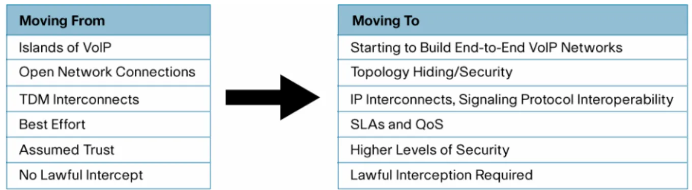
Figure 1. Changing Service Provider Landscape
Today’s SBCs must allow operators to scale a wide range of applications over networks whose peer connections are increasing in size, number, and type (for example, service provider-to-service provider, or service provider-to-enterprise). SBCs must also provide comprehensive network security. Operators must honor SLAs with peers and customers, as well as regulatory directives regarding lawful session interception. This paper examines some important considerations for SBCs in this new world.
THE ROLE OF SBC CAPABILITIES
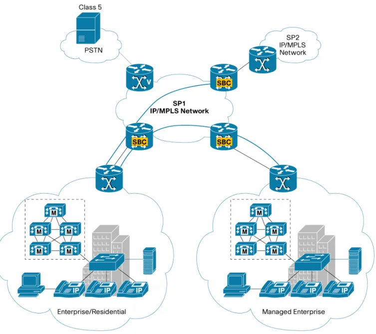
SBC capabilities, deployed at IP network boundaries, manage real-time multimedia traffic flows between IP networks. The precise function of a given SBC will vary depending on the type of networks it interconnects. For example, an SBC between a service provider and a managed enterprise VoIP network may not need to perform protocol interworking, whereas a service provider-to-service provider peering SBC may (refer to Figure 2).
Figure 2. Network Peering Points for SBCs
To date, SBCs have been used mainly to interconnect peer service provider networks. Based on their experience, service providers have clear ideas of the advantages and disadvantages of various SBC deployment models, and have firm opinions as to how to use them to advantage to scale and
Service Provider-to-Service Provider Interconnect
One of the first commercial VoIP applications involved service providers bypassing TDM toll charges by handing off calls to IP-based networks. Many “pureplay” VoIP carriers arose, promising highly reduced tariffs for international calls. These carriers connected predominantly with other startup carriers using VoIP and the H.323 signaling protocol. At the time, the vast majority of local-to-long distance carrier handoffs were still TDM-based. Now, with increasing VoIP adoption, TDM interconnect is decreasing, and it is no longer just the pureplay VoIP carriers interconnecting. However, many H.323 VoIP networks still operating must interconnect to a wide number of VoIP networks architected around SIP and IMS.
Service Provider-to-Enterprise Peering
With the rapid growth in IP telephony and the collapse of voice, video, and data onto a single business enterprise network connection, service providers are deploying SBC functions at the edge of their network, facing their enterprise customers. Some of the services they are offering include: IP private branch exchange (PBX)-to-service provider peering; VPN interworking, connecting multiple independent customers, each with multiple sites in their VPN; and enterprise-to-hosted IP telephony services interworking.
Because service providers have little control over the signaling protocols their customers choose, they must provide protocol interworking between different enterprises, and between the enterprise and the service provider. For example, if a service provider serves an enterprise using H.323 for all voice and video communications, and an enterprise using SIP for all voice and video communications, the service provider must ensure that the calls can be translated from H.323 to SIP, and conversely.
Service Provider-to-Residential Interconnect
With the advent of packet cable VoIP systems, IP-based DSL access multiplexers (DSLAMs) and broadband loop carriers, and Class 5-capable softswitches, VoIP spread to access networks. Increased bandwidth provided by advanced cable, DSL, and passive-optical-network (PON) systems has been affected by service providers’ desire to offer a richer set of consumer services, such as IP-based television and video on demand. Two-way multimedia applications, such as gaming and instant messaging, expand consumer choices far beyond basic telephone service. These applications often require consumer electronics devices such as personal computers, gaming consoles, and audio-visual systems. Intense competition for consumers’ profit share will ensure that IP-based services in the access network will continue to grow in number and diversity.
Original SBC deployments focused on service provider-to-service provider interconnects, limiting the required feature set but also limiting the total number of deployments. In contrast, enterprise and residential VoIP interconnects explode the number of network boundary points, application, and session types that SBCs need to support, but SBC deployments will explode at the same time. Service providers will need SBCs that can match network growth, while allowing profitable deployment of new and expanded services.
KEY DIFFERENTIATORS OF SBCS Appliance Versus Integrated Service Card
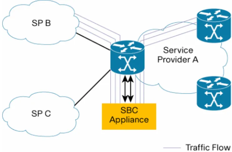
Early network deployments of SBCs followed an overlay model. SBC devices were inserted into the network alongside and connected to network peering routers (refer to Figure 3). Voice traffic was mapped through the peering router to an exit interface that connected to the SBC, which performed functions such as Network Address Translation (NAT) traversal, and then forwarded the traffic back to the peering router for routing toward its intended destination. Although this model has worked, it requires more footprint in the telecom rack for the SBC “appliance” and the added expense of interface transceivers to pass traffic back and forth between the peering router and the SBC. The SBC appliance must also be provisioned and managed separately from the peer router.
Figure 3. A Standalone SBC Appliance
Newer implementations integrate and update the SBC function within the peering router (refer to Figure 4). Integrating SBC capabilities into a peering router provides significant benefits. First, provisioning is simpler because the SBC function and the peering router use the same management interfaces. Second, an integrated SBC takes no additional space in the equipment rack. Furthermore, the operator no longer needs to “use up” expensive optical interfaces simply to route traffic from the peering router to the SBC and back again—all traffic is now contained within the peering router. Most importantly, the SBC can now talk directly to router line interface cards to implement additional functions, such as mitigating SBC-targeted denial-of-service attacks by directing ingress line interfaces to drop offending packets. In addition, the integrated SBC can take advantage of advanced QoS capabilities inherent in carrier-class routers.
Only integrated SBCs will provide scalability demanded by the growth of service provider-to-enterprise peering, service provider-to-residential management, and the continued increase of service provider-to-service provider interconnection. As peering points increase, operators will simply not be able to afford the exponential expense of superfluous transceivers and for power and cooling and management for standalone SBC appliances.
Unified Versus Distributed
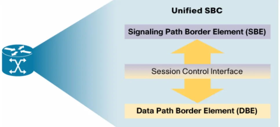
SBC functions can be broadly divided into two logical sub-elements. The signaling path border element (SBE) provides signaling functions such as protocol interworking (for example, H.323 to SIP), identity and topology hiding, and Call Admission Control (CAC). The data path border element (DBE) provides media-related functions such as deep packet inspection and modification, media relay, and firewall support under SBE control. To date, the SBE and DBE logical elements have generally been realized within a single, physical, SBC device. This model is referred to as unified (refer to Figure 5).
Figure 5. The Unified SBC Model
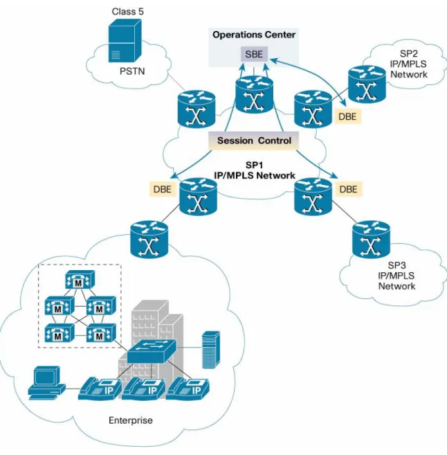
However, many carriers are finding that as their voice networks grow, the challenges of managing the networks grow proportionately. Service providers today want the option to decouple SBC bearer functions from signaling functions. They want to be able to distribute SBE functions in the network separately from the DBE element to simplify management, operations, and troubleshooting (refer to Figure 6). In this distributed model, communication between the SBE and DBE takes place over a well-defined standard, such as ITU-T H.248, allowing a multiplatform network implementation of the SBE and DBE elements.
A flexible SBC supports both the unified and the distributed model. Networks continually grow and evolve, and a multimedia IP transport network that scales adequately today with a unified SBC will likely outgrow the unified model and necessitate a distributed approach. Operators want SBCs that can grow with their networks—they do not want capital-intensive complete equipment upgrades of in-service network elements.
Figure 6. Distributing the SBC DBE Function in Service Provider Networks
SBC FOR THE CISCO XR 12000
Cisco Systems® embeds comprehensive SBC capabilities in the Cisco XR 12000 Series routers with a series of service cards that transparently integrate the SBC function into the Layer 2 and Layer 3 services of the routers, eliminating the need for overlay networks and standalone SBC appliances.
SBC for the Cisco XR 12000 expands upon the SBC capabilities of the successful Cisco Multiservice IP-to-IP Gateway, providing an open and flexible architecture for service provider deployments, and offering service provider-to-service provider peering and service provider-to-access network border control. Supporting both unified and distributed signaling deployments, SBC for the Cisco XR 12000 provides unmatched flexibility
The modular design of the Cisco XR 12000 Series routers allows network operators to cost-effectively scale their multimedia IP transport networks by adding additional capacity only as needed. They further benefit by deploying an SBC merely as an additional services card—exploiting common power, cooling, and switching fabric systems—rather than commissioning a nonintegrated, standalone SBC device.
The integrated Cisco XR 12000 SBC also simplifies provisioning and operations. It is managed by existing command-line interfaces and management systems, and does not require a separate management interface for the peering router and the SBC. The tight integration between the SBC function and Layer 2 and Layer 3 services allows operators to map customer VPNs through the peering point without having to additionally map the VPNs out an interface on a VLAN to an external SBC.
Complete support for H.323, SIP, and other signaling protocols paves a path for building future IMS architectures on existing Cisco transport networks. The Cisco XR 12000 SBC helps enable the Cisco Service Exchange Framework (SEF), which extends and expands on the standard IMS architecture. The Cisco SEF spans mobile, wireline, and packet cable technologies, allowing service providers to deliver a wider range of applications through increased network intelligence. The Cisco SEF also gives service providers greater control over applications through an evolving service control plane; greater efficiencies, such as single policy enforcement points for multiple access technologies; and higher service availability through enhanced security. The Cisco SEF offers subscribers more services—and greater control over those services through personalization and self-selection.
The Cisco XR 12000 Series routers use Cisco IOS® XR Software to deliver numerous service possibilities for network operators. With the addition of the Cisco XR 12000 Series to its high-end routing product lines, Cisco Systems gives providers a graceful upgrade path for their installed base of Cisco 12000 Series routers as they transition toward a converged Cisco IP Next-Generation Network infrastructure.
CONCLUSION
Real-time, IP-based multimedia applications offer a growing revenue stream for service providers, they are fun for consumers, and they provide productive tools for business enterprises. Multimedia applications are quickly spanning multiple transport networks, including wireless, wireline, and packet cable, prompting a need for management and control. Cisco SBC provides this management and control at network peering points and for different domains of authority. The IMS architecture, originally conceived for mobile networks, is quickly gaining acceptance in fixed wireline and packet cable networks. An element of the Cisco IMS strategy, SBC for the Cisco XR 12000 Series routers, with Cisco IOS XR Software, delivers a flexible solution that helps service providers meet the needs of their growing, dynamic, IP-based multimedia networks.
Corporate Headquarters
Cisco Systems, Inc. 170 West Tasman Drive San Jose, CA 95134-1706 USA
www.cisco.com Tel: 408 526-4000
800 553-NETS (6387) Fax: 408 526-4100
European Headquarters
Cisco Systems International BV Haarlerbergpark
Haarlerbergweg 13-19 1101 CH Amsterdam The Netherlands www-europe.cisco.com Tel: 31 0 20 357 1000 Fax: 31 0 20 357 1100
Americas Headquarters
Cisco Systems, Inc. 170 West Tasman Drive San Jose, CA 95134-1706 USA
www.cisco.com Tel: 408 526-7660 Fax: 408 527-0883
Asia Pacific Headquarters
Cisco Systems, Inc. 168 Robinson Road #28-01 Capital Tower Singapore 068912 www.cisco.com Tel: +65 6317 7777 Fax: +65 6317 7799
Cisco Systems has more than 200 offices in the following countries and regions. Addresses, phone numbers, and fax numbers are listed on the Cisco Website at www.cisco.com/go/offices.
Argentina • Australia • Austria • Belgium • Brazil • Bulgaria • Canada • Chile • China PRC • Colombia • Costa Rica • Croatia • Cyprus Czech Republic • Denmark • Dubai, UAE • Finland • France • Germany • Greece • Hong Kong SAR • Hungary • India • Indonesia • Ireland • Israel Italy • Japan • Korea • Luxembourg • Malaysia • Mexico • The Netherlands • New Zealand • Norway • Peru • Philippines • Poland • Portugal Puerto Rico • Romania • Russia • Saudi Arabia • Scotland • Singapore • Slovakia • Slovenia • South Africa • Spain • Sweden • Switzerland • Taiwan Thailand • Turkey • Ukraine • United Kingdom • United States • Venezuela • Vietnam • Zimbabwe